Z November 2011
|
|
|
- Roderick Shields
- 5 years ago
- Views:
Transcription


 comprises ten pages und")
1 I /11 Z November Mai 2015 MKT Metall-Kunststoff-Technik GmbH & Co. KG Auf dem Immel Weilerbach MKT Injektionssystem VMU zur Verankerung im Mauerwerk MKT Injection system VMU for use in masonry The above-named construction product is hereby granted allgemeine bauaufsichtliche Zulassung ('national technical approval'). This allgemeine bauaufsichtliche Zulassung ('national technical approval') comprises ten pages und nine annexes. The product is granted the initial technical approval on Original version in German language
2 Nr. Z Page 2 of 10 8 November 2011 I GENERAL CONDITIONS 1 The allgemeine bauaufsichtliche Zulassung ('national technical approval') verifies the usability and applicability of the construction product in accordance with the Landesbauordnungen ('building regulations of the German Laenders' ). 2 Where the allgemeine bauaufsichtliche Zulassung ('national technical approval') places requirements on the specific expertise and experience of persons entrusted with the manufacture of construction products and construction types in accordance with the regulations of the German Laenders conforming to Article 17 section 5 of the Musterbauordnung ('Model Building Code'), it shall be ensured that this expertise and experience can also be proven via equivalent verification of other member states of the European Union. This shall also apply, where relevant, for equivalent verification submitted in accordance with the agreement on the European Economic Area (EEA) or other bilateral agreements. 3 The allgemeine bauaufsichtliche Zulassung ('national technical approval') does not replace the legally required authorisations, approvals and certifications for carrying out construction projects. 4 The allgemeine bauaufsichtliche Zulassung ('national technical approval') is granted without prejudice to the rights of third parties, particularly private intellectual property rights. 5 Manufacturers and distributors for the construction project shall, without prejudice to additional regulations in the "Special conditions", provide the user of the construction product with copies of the allgemeine bauaufsichtliche Zulassung ('national technical approval') and indicate that this allgemeine bauaufsichtliche Zulassung ('national technical approval') shall be present at the site of use. The public authorities concerned shall be provided with copies of the allgemeine bauaufsichtliche Zulassung ('national technical approval') upon request. 6 The allgemeine bauaufsichtliche Zulassung ('national technical approval') may only be duplicated in its entirety. Publication of extracts requires the approval of the Deutsches Institut für Bautechnik. Text and drawings in advertising materials shall not contradict the allgemeine bauaufsichtliche Zulassung ('national technical approval'). Translations of the allgemeine bauaufsichtliche Zulassung ('national technical approval') shall contain the note "This translation of the German original document has not been verified by the Deutsches Institut für Bautechnik". 7 The allgemeine bauaufsichtliche Zulassung ('national technical approval') may be withdrawn. The provisions of the allgemeine bauaufsichtliche Zulassung ('national technical approval') can be subsequently supplemented and amended, particularly where this is necessitated by new technical findings. Z /Entwurf /11
3 Nr. Z Page 3 of 10 8 November 2011 II SPECIAL CONDITIONS 1 Construction product and area of application 1.1 Construction product The MKT Injection System VMU (hereinafter referred to as the anchor) consisting of the MKT Injection Adhesive VMU or VMU Express, a perforated sleeve and an anchor rod with hexagon nut and washer (anchor type VMU-A or V-A) of sizes M8, M10 and M12 or an anchor rod VMU-AH of size M12 or an internally threaded sleeve (anchor type VMU-IG or VMU-IGH) of size M6 and M8. The anchor rod (including nut and washer) as well as the internally threaded sleeve are made from galvanized steel or stainless steel. The anchoring system is based upon bond and positive locking between injection adhesive, perforated sleeve, anchor rod or internally threaded sleeve and masonry. Annex 1 illustrates the anchor when installed. 1.2 Area of application The anchor may be used for anchorage with primarily static loads provided that there are no requirements to fire resistance duration on the overall construction including the anchor. The temperature in the adhesive area may not exceed 50 C, or 80 C short term. The anchoring base material shall consist of masonry in accordance with DIN The approved anchoring basematerials are specified in section 3.1, Table 3.1. The mortar shall at least conform to the requirements of standard mortar of mortar group II as well as those for thin-bed or lightweight mortar in accordance with DIN : , Annex A.3 or DIN V 18580: The anchor may also be installed in the joints of masonry. The anchor of galvanized steel may only be used in dry, interior locations, e.g. apartments, offices, schools, hospitals and sales rooms, with the exception of humid rooms. Stainless steel anchors with material numbers , and (additional marking "A4") may also be used in structures of corrosion resistance class III in accordance with the allgemeine bauaufsichtliche Zulassung "Erzeugnisse, Verbindungsmittel und Bauteile aus nichtrostenden Stählen" ('national technical approval' "Products, connections and components made of stainless steels"') Z Stainless steel anchors with material numbers or (additional marking "HCR") may also be used in structures of corrosion resistance class IV in accordance with the allgemeine bauaufsichtliche Zulassung "Erzeugnisse, Verbindungsmittel und Bauteile aus nichtrostenden Stählen" ('national technical approval' "Products, connections and components made of stainless steels"') Z Conditions for the construction product 2.1 Properties and composition The anchor dimensions and material values shall correspond to the specifications shown in the annexes. The material values, dimensions and tolerances of the anchor as well as the chemical composition of the injection adhesive not specified in this allgemeine bauaufsichtliche Zulassung ('national technical approval') shall correspond to the specifications submitted to the Deutsches Institut für Bautechnik, certification body and external monitoring body. Z /Entwurf /11
4 Nr. Z Page 4 of 10 8 November Packaging, storage and labelling Packaging and storage The two components of the injection adhesive are supplied unmixed in cartridges in accordance with Annex 5. The adhesive cartridges should be protected from sunlight and stored according to the installation instruction in dry condition at temperatures of at least +5 C to not more than +25 C Labelling The packaging, enclosed instruction sheet or delivery note for the anchor shall be marked by the manufacturer with a conformity mark (Ü-marking) in accordance with the conformity mark ordinance of the federal states. The identifying mark of manufacturing plant, approval number and complete trade name of the anchor shall also be indicated. Labelling may only take place if the requirements of section 2.3 are fulfilled. The injection adhesive cartridge should be labelled in accordance with the German hazardous materials ordinance and marked "MKT Injection Adhesive VMU" or "MKT Injection Adhesive VMU Express", specifying details on shelf life, danger identifiers and processing. The installation instructions supplied with the injection system should contain specifications on protective measures for handling hazardous materials. The anchor is specified by the product name and thread size, e.g. MKT Injection System VMU M10. Each anchor rod or internally threaded sleeve should be stamped with the identifying mark of the manufacturer, anchor size and anchorage depth (anchor rod) according to Annexes 2 and 3. Stainless steel anchors with material numbers , and are additionally stamped with "A4". Stainless steel anchors with material numbers and are additionally stamped with "HCR". The required anchorage depth shall be visible from the marking on the anchor rod illustrated in Annexes 2 and Certificate of conformity General information Conformity of the anchor with the conditions of this allgemeine bauaufsichtliche Zulassung ('national technical approval') must be confirmed for each manufacturing plant with a certificate of conformity based on factory production control and regular external monitoring including an initial test of the anchor in accordance with the following conditions. The test plan submitted to the Deutsches Institut für Bautechnik and external monitoring body for the scope, nature and frequency of the production control shall apply. The certification body shall provide the Deutsches Institut für Bautechnik with a copy of the certificate of conformity it has granted for its record Factory production control Factory production control must be set up and implemented in each manufacturing plant. Factory production control includes continual monitoring to be undertaken by the manufacturer in order to ensure that the construction products it manufactures correspond to the conditions of this allgemeine bauaufsichtliche Zulassung ('national technical approval'). Factory production control should include at least the measures described below. The test plan submitted to the Deutsches Institut für Bautechnik and external monitoring body shall be applied for the scope, nature and frequency of the production control. The results of the factory production control should be recorded and evaluated. The records shall contain at least the following information: Z /Entwurf /11
5 Nr. Z Page 5 of 10 8 November Description of the construction product or base material and its components - Nature of the control or test - Date of manufacture and testing of the construction product or base material or components - Results of the control or testing and, where relevant, comparison with the requirements - Signature of the person responsible for factory production control. The records shall be stored for at least five years and submitted to the monitoring body responsible for external monitoring. These shall also be submitted to the Deutsches Institut für Bautechnik and the responsible oberste Bauaufsichtsbehörde ('highest construction supervision authority') upon request. Where test results are unsatisfactory, the manufacturer must immediately take the necessary measures to rectify the defect. Construction products that do not correspond to requirements should be handled in such a way that prevents confusion with conforming products. Once the defect is rectified, the relevant test should be immediately repeated provided that this is technically possible in order to prove that the defect has been rectified External monitoring Factory production control in each manufacturing plant shall be inspected regularly, at least once per year, via an independent inspection company. As part of the external monitoring, an initial test should be made and samples taken. The sampling and testing is the responsibility of the recognised independent inspection company. The test plan submitted to the Deutsches Institut für Bautechnik and external monitoring body shall be applied for the scope, nature and frequency of the external monitoring. The results of the certification and external monitoring shall be retained for at least five years. These shall also be submitted by the certification body or monitoring body to the Deutsches Institut für Bautechnik and the responsible oberste Bauaufsichtsbehörde ('highest construction supervision authority') upon request. 3 Conditions for design and dimensioning 3.1 Design The fastenings should be designed in accordance with standard engineering practice. Verifiable calculations and structural drawings should be prepared with regard to the loads to be anchored. Z /Entwurf /11
6 Nr. Z Page 6 of 10 8 November 2011 The approved anchoring base materials are specified in Table 3.1 below. Table 3.1 Approved anchoring base materials Anchoring base material 1 Solid brick in accordance with DIN DIN V 105-1: DIN V : Solid sand-lime brick in accordance with DIN DIN V 106-1: DIN V 106: Sand-lime perforated brick in accordance with DIN DIN V 106-1: DIN V 106: Vertically perforated brick in accordance with DIN DIN V 105-1: DIN V : Lightweight concrete hollow blocks in accordance with DIN DIN V 18151: DIN V : Hollow blocks in concrete in accordance with DIN DIN V 18153: DIN V : Mz 12 KS 12 KSL 4 HLz 4 Hbl 2 Hbn Dimensioning General information The fastenings should be dimensioned in accordance with standard engineering practice. Proof of direct local introduction of force into the concrete shall be provided. Transfer of the loads to be anchored in the component shall be shown in calculations. Bending stress of the anchor does not need to be considered if all of the following conditions are observed: - The component to be connected shall consist of metal and shall be clamped completely against the concrete without an intermediate layer in the area of the fastening. - The fixture shall be in contact with the bolt or rod over its entire thickness. - The diameter of the clearance hole in the fixture may not exceed the values in Annexes 8 and 9. Additional stresses that may arise in the anchor, the component to be connected or the component to which the anchor is fastened due to restricted deformation (e.g. during temperature changes) should be taken into account. Layers of plaster, gravel, lining or levelling courses are deemed to be non-load-bearing and shall not be taken into account in the anchoring depth. Z /Entwurf /11
7 Nr. Z Page 7 of 10 8 November 2011 The length of the bolt or threaded rod (including washer and nut) used with the internally threaded sleeve version shall, if not delivered by the manufacturer for the relevant application, be defined by the design engineer based on the thickness of the fixture to be connected, minimum screw engagement and any tolerances Approved loads The approved loads apply for tension, shear and inclined load at every angle. Approved loads in masonry walls. The approved loads of the anchor for fastenings in different masonry types are specified in Table 4, Annex 6. For fastenings in masonry built with perforated brick (HLz, KSL, Hbl and Hbn), the approved loads may be increased if the drilled hole has been made in rotation without hammer action. For sand-lime perforated brick, it shall also be proven that the outer web of the blocks are at least 30 mm (old bricks). In masonry made from vertically perforated brick the approved load may be increased in HLz 4 to 0.6 kn, in HLz 6 to 0.8 kn and in HLz 12 to 1.0 kn. In masonry made from sand-lime perforated brick the approved load may be increased in KSL 4 to 0.6 kn, in KSL 6 to 0.8 kn and in KSL 12 to 1.4 kn. In masonry made from lightweight concrete hollow blocks, the approved load may be increased in Hbl 2 to 0.5 kn and in Hbl 4 and hollow blocks made of concrete Hbn 4 to 0.8 kn. The maximum loads given in Table 5, Annex 6, shall not be exceeded for a single block loaded by a single anchor or anchor group. The lowest value from Tables 4 and 5 including any increase for rotation only drilling is decisive. For anchor pairs and groups of four anchors with shorter spacing (min a red a< a) as specified in Annexes 8 and 9, the approved load per anchor for anchoring in solid brick (Mz), solid sand-lime brick (KS), vertically perforated brick (HLz) and sand-lime perforated brick (KSL) should be reduced according to Annexes 8 or 9 to the value 'red F'. The anchors shall be configured in accordance with Annex 8. For anchoring in lightweight concrete hollow blocks (Hbl) and concrete hollow blocks (Hbn) the spacing shall not be reduced according to Annex Anchor distances and component dimensions The installation values and required spacings and edge distances as well as minimum thickness of masonry are specified in Annexes 8 and 9. See Annex 8 for definitions of dimensions Bending stress The approved bending moment is specified in Annex 6. The theoretical bending point is located one thread diameter behind the surface of the anchoring base material. Plaster, tiles and similar are deemed to be non-load-bearing. When an anchor is subjected to bending and additional tension loads, the tensile load component in place shall not exceed the following value: Fz appr. F (1 M / appr. M) appr. F = approved load according to Annex 6 appr. M = approved bending moment according to Annex 6 Fz = applied tensile load component M = applied bending moment In the case of external cladding with variable bending stresses (e.g. as a result of temperature changes) the alternating stress amplitude σ A = ± 50 N/mm² shall not be exceeded by the mean value σ M, based upon the calculated stress in the cross section of the thread of the anchor rod or bolt. Z /Entwurf /11
8 Nr. Z Page 8 of 10 8 November Displacement behaviour Under loads equivalent to the approved loads according to Annex 5, the following displacements are to be expected in the direction of the load with single anchors and anchor groups: Tension load: up to 0.3 mm Shear load: up to 1.0 mm Under continuous loading equivalent to the approved loads, additional displacements of up to 0.2 mm may occur. Under shear load, any hole clearance between the anchor and fixture should also be taken into account. 4 Conditions for implementation 4.1 General The anchor may only be used as a fastening system as supplied by the manufacturer. Individual parts may not be replaced. Commercial standard threaded rods, washers and hexagon nuts may also be used if the following requirements are fulfilled: - material, dimensions and mechanical properties in accordance with Annex 4, Table 1 and 2, - confirmation of material and mechanical properties by inspection certificate 3.1 according to DIN EN 10204:2005, the documents shall be retained, - marking of the threaded rod with the required embedment depth (see Annexes 2 and 3). This may be done by the manufacturer or the person on the jobsite. The anchor to be fastened should be installed in accordance with the construction drawings prepared pursuant to section 3.1 and the installation instructions of the manufacturer. Before installing the anchor, the anchoring base material should be determined. With masonry, this shall conform to the strength classes assigned to the approved loads in accordance with Annex 6. Installation in joints is permissible. For anchoring with an internally threaded galvanized steel sleeve, the fixing bolt with washer or threaded rod with washer and nut shall be galvanized 5 μm in accordance with DIN EN ISO 4042 and conform to strength class 5.8 in accordance with DIN EN ISO For anchoring with an internally threaded stainless steel sleeve (material numbers , , , and ) the fixing bolt with washer or threaded rod with washer and nut shall be of the same material as the internally threaded sleeve and shall conform to strength class 70 in accordance with DIN EN ISO Drilling and cleaning the hole The hole should be drilled at a right angle to the surface of the base matreial using a carbide impact or hammer drill bit. The carbide drill bits must comply with the specifications of the information leaflet "Kennwerte, Anforderungen und Prüfungen von Mauerbohrern mit Schneidköpfen aus Hartmetall, die zur Herstellung der Bohrlöcher von Dübelverankerungen verwendet werden" ('Characteristics, requirements and tests of drill bits with carbide cutting tips used for drilling holes for anchoring" in its version of January Adherence to the drill bit characteristics must be proven in accordance with section 5 of the information leaflet. Nominal drill-bit diameters and drill hole depths should correspond to the values shown in Annexes 8 and 9. Aborted drilled holes should be filled with mortar. The drilled hole should be cleaned in accordance with the installation instructions of the manufacturer by at least 2x blowing out, 2x brushing and 2x blowing out. For brushing, the corresponding cleaning brush defined in Annex 5 should be used. The diameter of the cleaning brush shall be not less than 18 mm. If the brush pushes into the drilled hole without resistance, a new brush should be used. Z /Entwurf /11
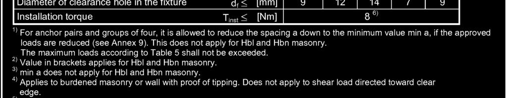
9 Nr. Z Page 9 of 10 8 November Installation of the anchor Anchoring in solid brick can be installed with or without a perforated sleeve. Anchoring in perforated brick shall always be installed with the corresponding perforated sleeve. The perforated sleeve should be inserted into the hole so that it finishes flush with the base material. Plaster, tiles and similar shall be removed from the anchoring area so that the perforated sleeve can be set flush with the base material. When using the internally threaded sleeve, the perforated sleeve and internally threaded sleeve shall always finish flush with the base material. The adhesive components are mixed by injecting with the static mixer supplied with the adhesive cartridges in accordance with Annex 5. The first full strokes of each container (approx. 10 cm) should be discarded and not used for anchoring. The permissible processing time of a cartridge including inserting the anchor rod or internally threaded sleeve should be taken from the installation instructions depending on the temperature of the cartridge and base material. The drilled hole should be filled with the required volume of injection adhesive specified in the installation instructions in accordance with Annex 5. The anchor rod is pressed into the adhesive by hand with a light turning motion up to the embedment depth mark into the completely filled perforated sleeve or into the filled drilled hole. The internally threaded sleeve is pressed into the adhesive by hand with a slight turning motion until it is flush with the surface of the base material, into the completely filled perforated sleeve or into the filled drill hole. If work is interrupted for a longer period than the specified processing time (see installation instructions of the manufacturer), the static mixer shall be replaced. The temperature of the adhesive shall be at least +5 C when dispensing. The temperature of the base material during hardening of the injection adhesive shall not be less than -5 C. The curing time until load is applied shall be observed in accordance with Annex 7. If the fixture is not in direct contact with the perforated sleeve/ base material, a levelling layer of mortar or a shim should be used taking into account any bending stress in accordance with section When using an internally threaded sleeve, the minimum thread engagement of the bolt/threaded rod should be observed in accordance with Annexes 8 and 9. Use a torque wrench when installing the fixture, the torque specified in Annexes 8 and 9 shall not be exceeded. 4.4 Verifying the anchor load-bearing capacity The capacity of the anchor should be tested by applying a load test on 3 % of the anchors which are installed in one component, with a minimum of 2 anchors tested of each size. The test is considered passed when no visible displacement occurs during the test loading with up to 1.3 times the approved tensile load in accordance with Annex 6. If one anchor does not pass, an additional 25 % of the anchors (at least 5) in the component, should be tested. If another anchor does not pass, all anchors of this component should be tested. Any anchors, that does not fulfil the required conditions shall not be used for load transfer. A test report should be written of the anchor capacity, including the location of the anchors tested, specifying the component, the applied load and the result. The report should be retained with the construction documentation. Z /Entwurf /11
10 Nr. Z Page 10 of 10 8 November Inspecting the anchor installation When installing anchors, either the contractor entrusted with installation of the anchors, the construction manager appointed by the contractor or an expert representative of the construction manager shall be present on the construction site. This person should ensure proper implementation of the work. When installing anchors, records should be made by the construction manager or his/her representative of the base material (masonry type, strength class and mortar group), the temperature in the anchoring base and the proper assembly of the anchors. The records shall be present at the construction site throughout the construction project and should be presented to the person responsible for construction monitoring upon request. Like the delivery notes, these shall also be retained by the contractor for 5 years after completion of the work. Andreas Kummerow Referatsleiter beglaubigt Lange Z /Entwurf /11
11 Nr. Z of 8 November 2011 Z /11

12 Nr. Z of 8 November 2011 Z /11

13 Nr. Z of 8 November 2011 Z /11
14 Nr. Z of 8 November 2011 Z /11


15 Nr. Z of 8 November 2011 Z /11
16 Nr. Z of 8 November 2011 Z /11
17 Nr. Z of 8 November 2011 Z /11


18 Nr. Z of 8 November 2011 Z /11
19 Nr. Z of 8 November 2011 Z /11