Dubai s Wasl Tower a Case Study for Cultural Sustainability in the Middle East. Holger Hinz, Principal, Werner Sobek Group
|
|
|
- Adele Park
- 5 years ago
- Views:
Transcription

1 Dubai s Wasl Tower a Case Study for Cultural Sustainability in the Middle East Holger Hinz, Principal, Werner Sobek Group
2
3 CTBUH 2018 Middle East Conference Polycentric Cities Building an Efficient Structure and Skin for an Expressive Tower Al Wasl Tower, Dubai Dipl.-Ing. Holger Hinz Werner Sobek Dubai 23 October 2018
4 Structure

5

6 Max. possible width for tower 36 m Setting out plan

 Slenderness 1/26!")
7 Tower Geometry and Structure 63 floors Office/Hotel/Serviced Apartments/High-Residential Slenderness 1/8.1 (based on external columns) Slenderness 1/26! (based on concrete core) 36 m 58 m 304 m
8 Regular floor

9 Sky lobby Residences Pool Deck/Spa Parking Mechanical levels Residences Luxury Hotel Hotel Apartments/Hotel Hotel Offices Hotel Overview tower utilization
10 64 different floor geometries

11 64 different floor geometries
12 Overall structural model


13 Inclined columns Deviation forces Model details
14 material and slab properties concrete grade 50 (C50) f c = 50 N/mm² E = 33,234 N/mm² h = 300 mm drop panel thickened stripe reduced thickness h = mm h = mm h = 250 mm Composite column p/t slabs


15 p/t slabs

16 Foundation

17 Foundation


18 Core walls


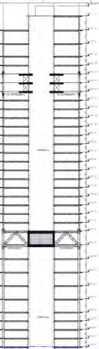
19 Type 1 Type 2 Outriggers

20 Outriggers


21 Outriggers

22 1st opt. 2nd opt. 3rd opt. Frame system Def. = 1,415 mm 717 mm 436 mm Eigenfreq. = 0.08 Hz 0.11 Hz 0.15 Hz Stiffness study
![Flächendicke n d [mm] 180.0 500.](/docs-images/88/115677321/images/23-0.jpg "0 700.0 900.0 Isometrie 0 700.")


23 Flächendicke n d [mm] Isometrie Flächendicke n d [mm] Isometrie 4th opt. 5th opt. 6th opt. Belt truss + Outriggers Def. = 478 mm 439 mm 547 mm Eigenfreq. = 0.14 Hz 0.14 Hz 0.13 Hz Outriggers Stiffness study


24 Wind tunnel model (1/500) Aero-elastic model study investigation of the dynamic behaviour of the tower Wacker Ingenieure, Wind Engineering

25 Tower Deflections due to wind loads Tip delections u,x = 510 mm < L/500 = 584 mm u,y = 330 mm < L/500 u,x u,y Horizontal deformations


26 1st Eigenmode f1 = 7.4 s 2nd Eigenmode f2 = 6.8 s 3rd Eigenmode f3 = 3.5 s Natural frequencies

27 Peak accelerations Tab.: Maximum horizontal peak accelerations and torsional velocities for the top occupied residential floor (level 59) of the Al Wasl Tower Tip accelerations


28 ThyssenKrupp Test Tower Quelle: GERB Schwingungsisolierungen GmbH & Co. KG Pendulum

29 Column design, WSD planning High stiffness contributes to overall building stiffness Composite columns
 no formwork required for concrete sustainable material (steel recycling, less concrete/cement) Notes")
30 Advantages mainly pressure loaded element high strength and ductility fire-resistant element comparatively small cross-sectional dimensions more leasable area more transparency low manufacturing tolerances due to steel elements low labor cost pre-fabricated elements (faster erection) no formwork required for concrete sustainable material (steel recycling, less concrete/cement) Notes Arrangement of steel plates/steel inlays flexible Composite columns

31 Column Schedule


32 Various high-rise buildings worldwide have been executed with composite columns. Testing machine 10,000 kn Source: Spannverband Composite columns


33 Load (max) Nd = 40,200 kn Dimension Ø mm Typical cross section Load (max) Nd = 38,000 kn Dimension Ø mm Typical cross section Geilinger-Column


34 HEMT, Munich, Germany

35 Alternative structural systems


36 4. 5. Alternative structural systems Belt Truss


37 Final model WSD
38 Facade
")

39 Tower Facade Overview City side (mainly South) GLASS: 40% OPAQUE: 60% Sea side (mainly North) GLASS: 52% OPAQUE: 48% City side Facade 1,800 mm unitized facade Sea side Facade 2,700 mm unitized facade

40 Tower Facade Components Insulated Glass Unit Opaque Glass Spandrel Aluminum Mullion Ceramic Fin


 layout")
41 Tower Facade Layout and Staggering Staggered layout (1,800 mm) Staggered layout (2,700 mm)


42 Tower Facade Ceramic fins Fin concepts


43 Tower Facade Ceramic fins, typical substructure Substructure of the fins SH 100 x 50 x 6 mm Bedded aluminum sheet t = 4 mm Edges profiles 90 x 10 mm Edges profiles 90 x 8 mm Edges profiles 80 x 8 mm Edges profiles 70 x 8 mm

 Type")
44 Tower Facade Twist (Typ 1C) Facade Type 1C


45 Tower Facade Vertical Boulevard Stick System
46 Sustainability
47 Sustainability concept The Al Wasl Tower goes beyond the purely reduction of the energy demand, extending the sustainability to all aspects related to the building and in particular focusing on the human needs. Energy Concept Facade Design Comfortable Indoor Optimal light Renewable energies Local materials Comfortable Outdoor Water management Less Materials Smart regulation Biosphere E-Mobility


48 Energy concept Scope Reduce the CO 2 emission of the building through an efficient supply integrating active and passive measures as well as renewable energies.

49 Facade Design Scope Reduction of the energy demand through a climate adapted facade design.


")

50 Facade Design Study on the solid/transparent ratio and shading elements of the facade Orientation: SE/SW 85% glazing (baseline) Reduced glazing 60% Inclined fins Vertical fins Vertical and horiz. fins


")

51 Facade Design Study on the solid/transparent ratio and shading elements of the facade Orientation: NE/NW 85% glazing (baseline) Reduced glazing 60% Inclined fins Vertical fins Vertical and horiz. fins

 Results")
52 Facade Design Results of the parametric study part 1 Results Northeast and Northwest cooling load (internal + external) Results Southeast and Southwest

53 Facade Design Results of the parametric study part 2 Results Northeast and Northwest external load Results Southeast and Southwest


54 Comfortable indoor Scope Provide the users the maximal indoor comfort, reducing to a minimum the energy consumption. Room 12 Room 11 Room 02 Room 01 Room 04 Room 06 Room 10


55 Comfortable indoor Investigation of user comfort analysis of the operative temperature Comfort ranges temperature: according to ISO 7730: 1,2 met and 1,0 clo, 45% rh, Air velocity 0.15 m/s

56 Comfortable indoor Investigation of user comfort analysis of CO 2 and humidity

57 Optimal light Scope Provide visual comfort through a bright indoor environment reducing the cooling energy.

58 Optimal light Interaction light and energy cooling loads Investigation of yearly cooling energy demand of the baseline Dry vent Cool W/m2 Room 11 Room 12 Room 10 Room 01 Room 04 Baseline U = 1.3 W/m²K g = 0.22 LT = Fins

59 Optimal light Interaction light and energy Daylight Factor 1 Daylight Factor of the baseline Room 11 Room 10 Room , ,5 Baseline U = 1.3 W/m²K g = 0.22 LT = Fins
60 Optimal light Interaction light and energy Daylight Factor 2 Daylight Factor with solar control glazing in corner rooms Room 11 Room 10 Room , ,5 Variation 4 (corner rooms) U = 1.1 W/m²K g = 0.19 LT = Fins


61 Optimal light Interaction light and energy Clear Sky conditions Room 10 Baseline - Room 10 Baseline - Room 10 Solar control glass - Illumination levels ( at 9 a.m.) Average: 2,640 lx - Average: 2,140 lx - Illumination levels ( at 3 p.m.) - Room 10 Solar control glass Average: 4,000 lx - Average: 2,640 lx


 U = 1.1 W/m²K g = 0.19 LT = 0.")
62 Optimal light Indoor Comfort Interaction light and energy Cooling load Investigation of yearly cooling energy demand with solar control glazing Dry vent Cool W/m2 Room 11 Room 12 Room 10 Room 01 Room 04 Room 04 Baseline Variation 4 (corner rooms) U = 1.1 W/m²K g = 0.19 LT = Fins

63 Energy concept Indoor Comfort Interaction light and energy Cooling load Investigation of yearly cooling energy demand in conjunction to the variation of the glazing
64 Energy concept Indoor Comfort Interaction light and energy Cooling load 4% reduction corresponds to savings of 10,333 kwh per floor and year. Saving 3,500 kwh/a * of electricity per floor which (= is a 4 Person household in Germany) Saving of 1.6 t CO 2-equi per floor 130 beech ** would be needed to counterbalance 1.6t CO 2-equ * According to the International Energy Agency a typcial SEER for air conditioning systems (seasonal energy efficiency ratio) in Middle East is 3 ** Each year a beech take up 12,5kg CO 2-equ, source co2online


65 Renewable energies Scope Reduce the Global Warming Potential through the use of clean energy produced on site. Studies of the integration of renewable energies Solar potential for PV integration on the rooftop a. b. a. Simulation model b. Solar radiation simulation c. PV layout c. 100% energy supply for the outdoor lighting + ca. 4 Tesla electric cars


66 Local materials Scope Improve the health of the users and preserve natural resource through sustainable materials. Study on the availability of certified material within a 500 km radium from Dubai
67 Stuttgart Buenos Aires Dubai Frankfurt Istanbul London Moscow New York