TRANSPORTATION RESEARCH BOARD. Seismic Design and Accelerated Bridge Construction. Wednesday, July 11, :00-4:00 PM ET
|
|
|
- Jonathan Bruce
- 5 years ago
- Views:
Transcription
1 TRANSPORTATION RESEARCH BOARD Seismic Design and Accelerated Bridge Construction Wednesday, July 11, :00-4:00 PM ET

2 The Transportation Research Board has met the standards and requirements of the Registered Continuing Education Providers Program. Credit earned on completion of this program will be reported to RCEP. A certificate of completion will be issued to participants that have registered and attended the entire session. As such, it does not include content that may be deemed or construed to be an approval or endorsement by RCEP.
3 Purpose Discuss the relationship between the use of accelerated bridge construction techniques and general seismic design performance. Learning Objectives At the end of this webinar, you will be able to: Understand seismic bridge design philosophy used as the basis of bridge design specifications Describe the challenges associated with ABC connections in high seismic regions Describe the effects that mechanical couplers may have on plastic deformation capacity of bridge columns Identify some of the novel materials and techniques available to improve seismic bridge response
4 TRB Webinar Seismic Design and Accelerated Bridge Construction (ABC) Lee Marsh PhD PE President BergerABAM 11 July 2018 Transportation Research Board Washington, DC Organized by TRB Committee AFF50
5 Presentation Objectives Review typical seismic design performance objectives Identify how these are achieved with current design methodologies Explore how ABC connection types affect seismic design Consider where we are in the development of deployable technologies

6 Seismic States for Site Class E
7 Three Principles of Seismic Design 1. Seismic design allows damage to specific elements of bridges 2. Bridges are made damage-tolerant by careful detailing of these elements 3. All other elements of the bridge are capacity protected to prevent damage to them

8 We Permit Earthquakes to Damage Bridges The forces induced if the structure is to remain undamaged can be too large to deal with, thus uneconomical
9 We Make Bridges Damage-Tolerant F F Evaluate at Maximum Response Plastic Hinge Ground Acceleration Ground Acceleration Yielding Structure Response Bridges can be built to perform in a ductile manner
10 Chain Analogy - Capacity Protection F ib F d Force, F F Brittle Links Ductile Link Brittle Links Force F d Ductile Behavior, Provided F d < All F ib Weakest F ib Brittle Behavior, If Any One F ib < F d Displacement, T. Paulay s Chain Analogy

11 Chain Analogy - Capacity Protection F ib F d Force, F F Brittle Links Ductile Link Brittle Links Force F d Ductile Behavior, Provided F d < All F ib Weakest F ib Brittle Behavior, If Any One F ib < F d Displacement,


12 Damage from Cyclic Inelastic Loading Spalling Onset 2.2% Drift Spalling Condition at 3.7% Drift Bar Buckling & Spiral Fracture 5.6% Drift SDC A Caltrans


13 Reduced-Scale ABC Column Tests Columns After Testing Bar Fracture Design Successful For High Seismic Regions! UW
14 What s Special About Seismic Applications? 1. Continuity of load path under load reversals 2. Development of cyclic inelastic deformations 3. Maximum forces (moments) occur where we would like to connect prefabricated elements 4. Certain element/material behaviors may cause rapid loss of cyclic resistance Local Buckling Strain Concentrations 5. Detailing is important!
15 A Few Words on Continuity of Strength In high seismic areas inelastic ductility is required; thus clearly all members must have sufficient strength to form the intended plastic mechanism. In low seismic (non-seismic) areas, continuity of strength is still required, just not the ductility (or deformation capacity). In low-seismic areas, there still needs to be lateral capacity commensurate with the minimum member strength requirements (e.g. 0.7 or 1 % minimum steel, etc)

16 Example ABC Connection Locations in a Bridge ED Energy Dissipating CP Capacity Protected

17 Definition of ABC-Type Connection

18 Where are the connections? ED Energy Dissipating CP Capacity Protected
19 Basic Steps of Seismic Design Step Basic Steps for Seismic Design 1 Determine Seismic Input 2 Establish Design Procedures 3 Identify the Earthquake Resisting System and Global Design Strategy 4 Perform Demand Analysis 5 Design and Check Earthquake Resisting Elements (Ductile or Other) 6 Capacity Protect the Remaining Elements


20 We Typically Analyze Bridges Elastically How can we estimate the inelastic displacement of the system? Can use linear elastic analysis to predict nonlinear displacements!
21 Displacement-Based Method (DBM) F Elastic Response F F Elastic Capacity Plastic Hinge F Yield F non-seismic Ensured Yielding System Displacement Capacity Is Directly Checked, Based on Actual Provided Detailing. (Confinement) Elastic Only Minimum Required Force, But No Unique Force Required
22 Inelastic to Elastic Response Two common methods: Coefficient Method (AASHTO LS and GS) Substitute Structure Method (Capacity Spectrum - Isolation) S a 5% >5% Solution Point S d Secant Stiffness T = Fundamental Period of System T s = Corner of Response Spectrum Area give effective damping based on hysteretic behavior
23 ABC Seismic Systems Two types of systems: System 1) Emulative behavior of normal RC systems Use current AASHTO Coefficient Method for demand (generally conservative of all such systems) System 2) Completely different hysteretic behavior Improved behavior (e.g. re-centering) Improved/controlled damping Controlled damage Use Capacity Spectrum Method for demand (still under development)
")
24 Ductile Design Activity - DBM P- Requirements (Minimum Strength) No Unique Resistance (Force) Required! Minimum Strength RC Members Demand Analysis Displacement Capacity Adjust Bridge Characteristics C D No Transverse Steel (Confinement & Shear) Strain Limits and Ductility Demand Limit (SDC D)
25 What s Special About Seismic Applications? 1. Continuity of load path under load reversals 2. Development of cyclic inelastic deformations 3. Maximum forces (moments) occur where we would like to connect prefabricated elements 4. Certain element/material behaviors may cause rapid loss of cyclic resistance Local Buckling Strain Concentrations 5. Detailing is important!
26 Grouped Similar Connection Types Generally Behavior is Emulative of RC Non-Emulative of RC Bar Couplers Grouted Ducts Pocket Connections Socket Connections Integral Connections (Connections Super to Piers) Emerging Technologies Prestress Tendons in Tandem with Deformed Bars Shape Memory Alloy and ECC Replaceable Elements (Either Emulative or Not)
27 Grouped Similar Connection Types Generally Behavior is Emulative of RC Non-Emulative of RC Bar Couplers Grouted Ducts Pocket Connections Socket Connections Integral Connections (Connections Super to Piers) Emerging Technologies Prestress Tendons in Tandem with Deformed Bars Shape Memory Alloy and ECC Replaceable Elements (Either Emulative or Not)


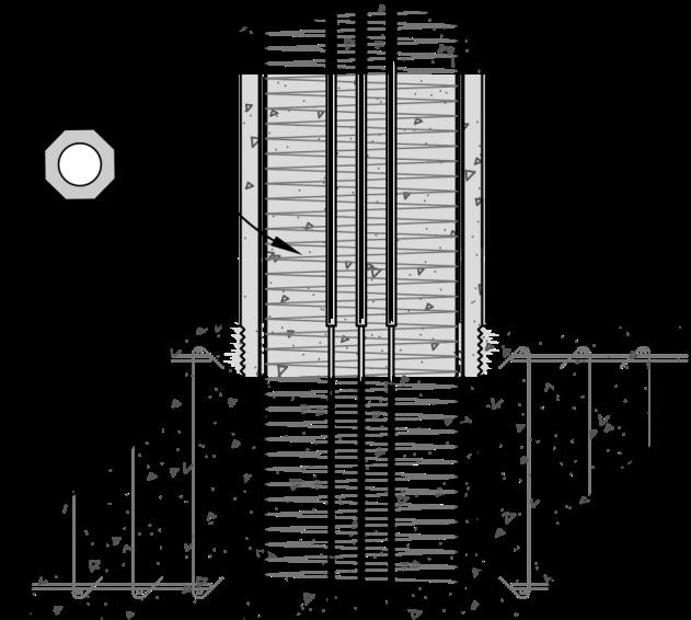
28 Bar Coupler Connections This type: grouted-sleeve connection Note that the stiffening presence and non-yielding length of the coupler can substantially decrease the ductility of the connection relative to continuous reinforcing bars.


29 Grouted Duct Connections NCHRP WSDOT


30 Pocket Connections NCHRP 12-74

31 Member Socket Connections Plastic Hinge Embedded Column In Blocked out Footing Embedded Column In CIP Footing Note that these connections can be made generally emulative of reinforced concrete connections.


32 Socket Connection Using Block Outs Steel Pile Bent with Precast Cap Beam BergerABAM

33 Socket Connections in CIP Footing Precast Column with Cast-in-Place Footing BergerABAM
34 Socket Connection Internal Forces Socket Connection Must be Capable of Transferring Forces To Footing or Pile Cap in High Seismic Areas Plastic Hinge Univ of WA

35 Precast Column Socket Connection - Lateral Load Test Footing undamaged Univ of WA
36 Drilled-Shaft Socket Connection Concept Plastic Hinge


37 Column-Shaft Tie Reinforcement Shaft Transverse Reinforcement Must Be Capable of Resisting Splitting Forces in High Seismic Areas University of Washington


38 Integral Connection Systems Two-Stage CIP Cap Beam with Precast Prestressed Girder Superstructure Girders are made continuous over bents for live and lateral loads.
 Two-stage cap Upper stage CIP Girders integral with combined lower and upper stages of cap (CP) WSDOT HfL")
39 Precast Bent System for High Seismic Regions Member socket connection at base (ED) Few, but large, bars at precast cap connection (ED) Two-stage cap Upper stage CIP Girders integral with combined lower and upper stages of cap (CP) WSDOT HfL Project


40 Longitudinal Loading Moments at Two-Stage Cap Longitudinal Movement Superstructure Moment Column Overstrength Moment, M po Column Longitudinal Moment Resisted Entirely in Upper Stage (Superstructure)
41 Longitudinal Joint Considerations Joint Forces Resolved In This Region Bottom (Positive) Steel Critical Plastic Hinge Design Example in Highways for LIFE Reports
 Effective In These Zones Design Example in Highways for LIFE")
42 Two-Stage Cap Longitudinal Joint Width Plastic Hinge Transverse Steel (Stirrups) Effective In These Zones Design Example in Highways for LIFE Reports


43 Precast Pier System: Demonstration Project and Design Specifications WSDOT, BergerABAM, UW Highways for LIFE Technology Partnerships Program
44 Grouped Similar Connection Types Generally Behavior is Emulative of RC Non-Emulative of RC Bar Couplers Grouted Ducts Pocket Connections Socket Connections Integral Connections (Connections Super to Piers) Emerging Technologies Prestress Tendons in Tandem with Deformed Bars Shape Memory Alloy and ECC Replaceable Elements (Either Emulative or Not)


45 Hybrid Connections / Non-Emulative Systems Force Displacement Energy Dissipation & Re-centering Post - PT provides re-centering Rebar provides energy dissipation MCEER / SUNY Buffalo This is but one such system. A number of such systems are under development.
46 Recall - Inelastic to Elastic Response Two common methods: Coefficient Method (AASHTO LS and GS) Substitute Structure Method (Capacity Spectrum - Isolation) S a 5% >5% Solution Point S d Secant Stiffness T = Fundamental Period of System T s = Corner of Response Spectrum Area gives effective damping based on hysteretic behavior
47 Technology Readiness Level (TRL) Conceptual Example Technology Readiness Level (TRL) % of development complete TRL Description Concept exists 2 Static strength predictable infill 3 Non-seismic deployment " 4 Analyzed for seismic loading " 5 Seismic testing of components 6 Seismic testing of subassemblies 7 Design & construction guidelines 8 Deployment in seismic area 9 Adequate performance in EQ catch-up required " advancement TRL Concept Developed by NASA
48 General Observations All systems require some: Infill = additional knowledge Advancement = higher level of readiness Catch-up (some do) = knowledge gaps that need closing No systems have endured the design earthquake and performed adequately; thus no TRL 9 systems.


49 National Cooperative Highway Research Program Published Documents: ABC Synthesis PBSD Synthesis ABC Recommended Specs Report 242 Recently adopted by AASHTO* * Expect ongoing and future tests will lead to improvements Specifications in Development: NCHRP Performance-Based Seismic Design (PBSD) Specifications
50 Thank You!
51 Systems for Accelerated Bridge Construction (ABC) in Seismic Regions: Overview John Stanton University of Washington 11 July 2018 Webinar organized by TRB Committee AFF50
52 Outline Decision tree of systems and connections. Connections that can be used with many systems. Selected systems for enhanced seismic performance.
53 Decision Tree ABC How? SPMT Lateral slide PBES Where? Connection Type Bents Emulative Enhanced Seismic UBPost-T UBPre-T SMA Other Socket X X X X x Pocket X X X X x Grouted duct X X X X x Other x x x x x Superstructure Design Concept System SPMT = Self Propelled Modular Transporter PBES = Precast Bridge Elements and Systems UBPre-T = UnBonded Pre-Tensioned SMA = Shape Memory Alloy
54 ABC & Enhanced Seismic Performance ABC using prefabricated elements requires a design approach different from that of conventional construction. ABC vs conventional construction for seismic: Can we get as good performance with ABC? Present approach: Life Safety. Can we get better performance with ABC? e.g. No residual drift. Low damage.


55 Design for Seismic and ABC Enhanced seismic Conventional ABC
56 Versatile Connection Types Connections concepts common to many systems: Socket connections Pocket connections Grouted ducts and sleeves Mechanical connections

57 Versatile Connections - Sockets WET SOCKET Column: PC concrete or CFT Footing: cip concrete DRY SOCKET Column: PC concrete or CFT Footing: PC concrete Annular space: cip grout or concrete No steel crosses column-footing interface. Quick to construct. Best if h footing > 1.0 D col Well suited to footings. Less so for cap beams.

58 Sockets Precast Concrete Column STRUT AND TIE MODEL FORCES ON COLUMN Vertical load can be carried by friction

59 Pockets Precast Concrete Cap Beam Opening in cap beam. Fill with cip concrete Corrugated steel pipe PC cap beam. Column PC or cip

60 Pockets Precast Concrete Cap Beam Critical node - CTCT Force transfer from tensions steel: Steel to pocket concrete. Pocket concrete to corrugated tube. Tube to cap beam concrete. Good for cap beams, not footings.

61 Grouted sleeves and ducts SLEEVE: Joins two bars in tension. Sleeve transfers load by tension in wall. Thick walls. Proprietary brands. Placement tolerances quite tight. DUCT: Anchors bar in concrete. Duct not in axial tension. Can lap-splice other bars to outside of duct. PT duct thin wall. Nonproprietary. More generous tolerances.
62 Grouted sleeves and ducts WHERE TO PLACE SLEEVES? Consider both strength and deformation capacity. IN FOOTING Bars project from column. Potential for difficulty in transportation. Need to prevent entry of debris. Harder to access grout ports. Yielding in the column. IN COLUMN Easier to construct. Sleeve is stiff, inhibits plastic action in column. Inelastic action forced into bar in footing. Good bond short length risk of bar fracture. Yield zone

63 Mechanical connectors Courtesy HRC MECHANICAL CONNECTORS Tension butt-splice between bars. Shorter than sleeve. Less effect on plastic hinge zone. Need careful alignment for screw threads.
64 Emulative Systems Emulation Goal With a precast system, emulate the performance of a traditional c.i.p. system In most cases, Connection to be as strong as the column. Inelastic action occurs in the column. Avoid brittle failure modes (e.g. shear). Provide flexural ductility.
65 Emulative Systems Precasting the cap beam saves the most time, e.g. for: Shoring Formwork Steel fixing Casting-curing cycle Precasting the column saves some time, but: Contractors prefer to cast in place (keeps work in-house). Time savings are less than with cap beam.


66 Emulative Systems Grouted Ducts EMULATIVE SYSTEM Precast column with projecting bars Ducts in foundation/cap beam. All inelastic action in column. Just like c.i.p. Haraldsson, Stanton, Eberhard
 shown here. Second stage (i.e. diaphragm ) is cast in place with slab, after girder erection.")
67 Emulative Systems Grouted Ducts Precast cap beam on c.i.p. columns. (Contractor choice to save time). SR 520, Redmond WA. First stage cap beam (pc) shown here. Second stage (i.e. diaphragm ) is cast in place with slab, after girder erection.
68 Emulative Socket Connection Precast column Headed bars Roughened surface cip footing

69 Emulative Socket Connection
70 Emulative Socket Connection After seismic testing. All inelastic action in column. Foundation undamaged. Haraldsson, Stanton, Eberhard
71 Emulative Drilled-Shaft Connection

72 Emulative Drilled-Shaft Connection Strong column / weak shaft BAD Strong shaft / weak column GOOD Tran, Stanton, Eberhard
73 Emulative Concrete Filled Tube (CFT) Connection Concrete Filled Tubes (CFTs) for Seismic Resistance Courtesy Charles Roeder and Dawn Lehman, University of Washington
 and piers in")
74 Concrete Filled Tube (CFT) CFTs can be used as foundation elements (piles, shafts) and piers in elevated bridges
")
 Welded")
75 Concrete Filled Tube (CFT) Embedded Ring (ER) Welded Dowel (WD)


76 Emulative Systems - Summary Connections in Emulative Systems Summary ABC Emulative Systems All of the major connection types (Socket, Pocket, Grouted Sleeves or Ducts, Mechanical Connectors, CFTs) have been tested under cyclic loading. All can provide sufficient strength. Most can provide ductility equal to that of c.i.p. construction. Performance depends strongly on details.
77 Enhanced Seismic Performance To achieve more than Code performance (i.e. more than Life Safety): Most work on minimizing downtime and damage: Re-centering Zero residual drift no bridge closure. Minimizing damage to columns minimal repair costs. Combinations of the two. Re-centering can be achieved by: Unbonded prestressing. Shape Memory Alloy (SMA) reinforcement.

78 RE-CENTERING SYSTEMS Unbonded Post-tensioning: Two bees 28
79 Re-centering System Hysteresis Loops 100/0 75/25 50/50 Optimum: Max damping/ full re-centering PT/rebar 25/75 0/100
80 Generic Unbonded PT Bent PT, unbonded in the free height of the column. Remains elastic Bonded rebar yields cyclically, dissipates energy Column rocks as a rigid body: no curvature no strain no cracking Local high stress at interface. Needs protection


81 Unbonded PT (Rocking) Systems - End Protection Conventional concrete only Hybrid Fiber-Reinforced Concrete (HyFRC ) Steel tube confinement Re-centering Low Damage System Low Damage Detailing 31
82 Unbonded PT (Rocking) Systems - Variations cip column ABC??? Post-tensioning: cip or pc column. Site operation. Anchorage. Potential for corrosion. pc column Lifting weight. GCs prefer not. Shell column Light weight. Need int. and ext. steel shells. PT corrosion? Pre-tensioning: pc column only. Plant prestressing. No anchorages, no corrosion. Relies on bond.
83 Pre-T Precast System. (Low damage, re-centering) Thonstad, Stanton, Eberhard University of Washington

84 Pre-T Precast System Construction sequence Re-centering Low Damage System Construction Sequence 34


85 Pre-T Precast system Footing Connection: Wet Socket Re-centering Low Damage System Precast Connections 35


86 Pre-T Precast system Cap Beam Connection: Dry Socket & Grouted Duct. Re-centering Low Damage System Precast Connections 36
 Shake Table Test 2014 PreT Bridge Motion 21C 37")
87 Pre-T Precast system Shaking Table Test: 1995 Kobe /Takatori (PGA = 0.8g) Shake Table Test 2014 PreT Bridge Motion 21C 37
88 Low damage Unbonded Post-tensioned Connections with External Dissipaters. Courtesy Allessandro Palermo, University of Christchurch, NZ


89 Unbonded Post-T: External Dissipaters Low Damage Connections


90 Unbonded Post-T: External Dissipators Field Implementation - Wigram Magdala Bridge: detail of dissipater assembly


91 Unbonded Post-T: External Dissipators Installing Dissipater Connections


92 Unbonded Post-T: External Dissipators After installation
93 Low damage Unbonded Post-tensioned Dual Shell Columns. Courtesy Jose Restrepo, University of California San Diego
94 Unbonded PT Dual-Shell Column 44 44


95 Unbonded PT Dual-Shell Column Concentric Steel Shells Hollow-core composite section No need for formwork or rebars Post-Tensioning System PT bar and polyurethane bearing in series. Prevents PT bar from yielding. INTERNAL Energy Dissipators Unbonded stainless-steel dowels Grouted into column ducts Circumferential welds inside outer shell EXTERNAL Energy Dissipators Buckling-restrained hysteretic devices Connected to outer shell and footing Allow rotation at connections 45

 deep.")

96 Unbonded PT Dual-Shell Column Drift-Ratio Response Observed Damage Self-centering dual-shell column: Damage limited to the interface region. Mortar crushing, 1-in. (25-mm) deep. Energy dissipater fracture. Conventional RC column: Damage up to 2 diameters above base. Extensive concrete cover spalling. Longitudinal rebar fracture. 46
97 Enhanced Seismic - Summary Efforts to limit: Residual drift Damage Methods: Unbonded Prestressing, rocking. Several shown. SMA bars/ecc, bending. Not shown. See Saiidi. Open questions: System complexity. Pre-fabricate as much as possible. Post-EQ repair? Choice: Internal or external dissipators.
98 Build-your-own Solution Many new concepts have been developed. All those shown have been tested. Details are critical (as always!) Can mix and match to suit any particular application. But first be sure that the concept is clear. If you do not know how the structure should behave, it does not know either.


99 Build-your-own Solution An other Bridge C oncept
100 Thank You! Questions?
101 Mechanical Splices (Couplers) in and Adjacent to Plastic Hinge Regions and their Impact on Plastic Deformation Capacity of Bridge Columns M. Saiid Saiidi Professor, Department of Civil and Environmental Engineering Director, Center for Advanced Technology in Bridges and Infrastructure University of Nevada, Reno, USA
102 Couplers: Current US Code for Moderate and High Seismic Zones Code Coupler Type Plastic Hinge AASHTO Full Mech. Connection No Caltrans Service No Ultimate No ACI Type 1 No Type 2 Yes Unofficial reason for not allowing couplers in PH: Insufficient data on columns representing US practice
103 Topics 1. Couplers and Novel Materials in Earthquake Design 2. Couplers for Accelerated Bridge Construction 3. Couplers in Design for Deconstruction
104 1- Couplers and Novel Materials in Earthquake Design Performance during earthquake Serviceability after earthquake New


105 Target performance during earthquake: No Collapse
106 Serviceability after earthquake: Minimize permanent drift and damage
")

107 SMA (Nickel Titanium) Also military applications
108 Superelastic response Shape memory effects NiTi SMA developed in1962 Cu-Al-Mn SMA being developed Shape Memory Alloy

109 SMA Bar Application Very expensive! Approx. 90 x steel cost Limit its use only in plastic hinges Steel NiTi Steel


110 NiTi Bar Sizes and Connections Can be made up to 100-mm diameter UNR: 13-mm, 16-mm-, and 30-mm bars UNR: Threaded couplers; lock screw couplers; headed couplers
 1000 7 Polyvinyl Alcohol Fiber Tensile")
 5.6 4.2 2.8 1.")
111 Combining SMA Bars with Engineered Cementitious Composites (ECC, Ductile Concrete) Polyvinyl Alcohol Fiber Tensile Stress (psi) Conventional Concrete ECC Strain (%) Tensile Stress (MPa)
 Cyclic Load Plan 0 5 10 15 20 25 30 35 40 45 50")
112 16% 14% 12% 10% 8% 6% 4% 2% 0% -2% -4% -6% -8% -10% -12% -14% -16% Drift Ratio (%) Cyclic Load Plan Cycle
113 Conventional SMA/ECC


114 10% Drift Residual After 10% Drift Conventional SMA/Conc. SMA/ECC


115 HRC Couplers in Seattle Alaska Way Viaduct- CIP


116
117 Design Guidelines for SMA Columns


![com] Grouted Sleeve](/docs-images/88/116098677/images/118-2.jpg "[splicesleeve.")
![co Coupler m] [armaturis.](/docs-images/88/116098677/images/118-3.jpg "com] Threaded Bar Coupler Bar")
118 Topic 2 - Couplers for Accelerated Bridge Construction Headed Bar [hrc-usa.com] Coupler [erico.com] Grouted Sleeve [splicesleeve.co Coupler m] [armaturis.com] Threaded Bar Coupler Bar Grip (Swaged) [barsplice.com] Coupler Shear Screw Coupler [daytonsuperior.


119 Mechanical Rebar Couplers Current Study Upset Headed (UH) Ultimate coupler Service Coupler Grouted Sleeve (GS)
120 Phase I- 9 Half-Scale Column Models Caltrans Seismic Design Criteria (Disp. Ductility 5) Design Details 9ft Tall; 2ft Diameter 11 #8 Longitudinal Steel (1.9%) #3 2in Pitch (1%) Axial Load = 226kip (0.1f c A g ) Precast Hollow Shell Design Filled with SCC Use of Precast Pedestal No Pedestal Coupler Location w/ Pedestal


121 Connection Details HC Models Footing Connection Dowels Closure Form Grout Layer


122 HRC Couplers Close up Custom Built Length Fillers


123 Connection Details GC Models Connection Dowels Footing


124 Columns with Pedestal

125 Testing Drift (%) Cycle


126 5% Drift Push Cycle 2 CIP HCNP GCNP µ D = 3.6 F = 65.9 kip µ D = 3.2 F = 67.8 kip µ D = 3.7 F = 70.4 kip

 HCNP (2")
 GCNP (2 nd")
127 Observations Damage at Failure CIP (2 nd Cycle 10% Drift) HCNP (2 nd Cycle 10% Drift) GCNP (2 nd Cycle 6% Drift)
128 CIP -80 Force [kip] Drift [%] HCNP Drift [%] Force [kn] Force [kn] 356 Force [kip] 80 Force [kn] Force [kip] Force-Displacement Responses GCNP Drift [%]
129 Results - Pushover Curves
130 Effect of Couplers on Spread of Yielding Column Column Column Headed Coupler Device Grouted Coupler Device Footing CIP Footing HRC Couplers Footing Grouted Sleeve Couplers
131 Stress-Strain Model for Couplers Bar Region d b a.d b Rigid Length Coupler Region Coupler Region L sp L cr ß.L sp Stress Bar Region a.d b Bar Region Strain Test data: Haber et al. (2015) Straight Bar εε ssss εε ss = LL cccc ββll ssss LL cccc Stress (ksi) Grout Steel Sleeve ββ: Rigid Length Ratio 20 0 Measured in Coupler Region Calculated for Coupler Region Steel Bar Only Strain (in/in) Straight Bar
132 Parametric Study on Columns w/ Couplers Parameters: Coupler Length (L sp = 5d b, 10d b, and 15d b ) Pedestal Height (H sp =5d b, 10d b, 20d b, and 30d b ) Coupler Rigid Length Factors (β = 0.25, 0.50, 0.75) Coupler Vertical Spacing (S sp = 2L sp and 4L sp ) Displacement Ductility Capacity (m= 3, 5, and 7) Aspect Ratio (4, 6, and 8) Axial Load Index (5 and 10%) More than 660 pushover analyses 32
133 Proposed Ductility Equation Coupler Region Bar Region d b a.d b Rigid Length L sp a.d b L cr ß.L sp Column Section Couplers L sp Elem. 3 Elem. 2 L Bar Region Footing H sp Elem. 1 μμ ssss μμ CCCCCC = (1 0.18ββ) HH ssss LL ssss 0.1ββ 33
134 Proposed Modified Plastic Hinge Length Bar Region Coupler Region d b a.d b Rigid Length L sp a.d b L cr ß.L sp Column Section Couplers L sp Elem. 3 Elem. 2 L Bar Region Footing H sp Elem. 1 LL pp ssss = LL pp (1 HH ssss LL pp )ββll ssss LL pp L p is the AASHTO plastic hinge length: LL pp = 0.08LL ff yyyy dd bb 0.3ff yyyy dd bb 34

135 Topic 3 Couplers in Design for Deconstruction (DfD) Objectives: Develop structural member that 1- Withstand strong earthquakes with no or minor Damage so they are useable after earthquakes. 2- Can be disassembled and reused. Note: 6% of CO 2 emission in the world is from cement factories.


136 Column Test Models


137 Cu-Al-Mn Bars

138 Two-Span DfD Bridge Model


139 After disassembly

140 Reassembled Bridge Test to Failure (10% drift)
141 Message Bridge earthquake engineering community should be open to possible use of couplers in column plastic hinges. Columns w/ certain types of couplers perform as well as columns w/ no couplers. The limited drift capacity of some coupler types would limit their use to low and moderate seismic zones. Ease of construction varies among different coupler types. Specific acceptance criteria and design guidelines for seismic couplers are needed to provide the coupler option for ABC in moderate and high seismic zones (emerging).
142 Today s Speakers Elmer Marx, Alaska Department of Transportation and Public Facilities, elmer.marx@alaska.gov Lee Marsh, BergerABAM, lee.marsh@abam.com John Stanton, University of Washington, stanton@u.washington.edu M. Saiid Saiidi, University of Nevada, Reno, saiidi@unr.edu
143 Get Involved with TRB Getting involved is free! Join a Standing Committee ( Become a Friend of a Committee ( Networking opportunities May provide a path to become a Standing Committee member Sponsoring Committee: AFF50 For more information: Create your account Update your profile
144 Receiving PDH credits Must register as an individual to receive credits (no group credits) Credits will be reported two to three business days after the webinar You will be able to retrieve your certificate from RCEP within one week of the webinar

145