APPENDIX I NASP TEST PROTOCOLS
|
|
|
- Eleanor Gibson
- 5 years ago
- Views:
Transcription
1 APPENDIX I NASP TEST PROTOCOLS I-1
2 I-2
3 I-3
4 I-4
5 NASP STRAND BOND TEST (DRAFT) Standard Test Method to Assess the Bond of 0.5 in. (12.7 mm) and 0.6 in. (15.24 mm) Seven Wire Strand with Cementitious Materials 1. Scope 1.1 This test method provides a means to assess the ability of 0.5 in. (12.7 mm) and 0.6 in. (15.24 mm) seven wire strand to bond with concrete and other cementitious products. The method tests the bondability of strands that are made and intended for use as prestressing strands that conform to ASTM A This test does not purport to address all of the safety concerns, if any, associated with its use. It is the responsibility of the use of this test method to establish appropriate safety and health practices and determine the applicability of regulatory limitations prior to use. 2. Reference Documents 2.1 ASTM A ASTM C ASTM C ASTM C ASTM C ASTM C ASTM C Summary of the Test Method Test specimens are prepared by casting a single, 0.5 in. (12.7 mm) and 0.6 in. (15.24 mm) seven wire strand into a cylinder of concrete mortar with a bonded length of 16 in. (400 mm). The constituents and proportions for the concrete mortar mixture are prescribed. The concrete in the specimen is cured for approximately one day under controlled conditions. The specimen is tested at one day of age by pulling the strand through the mortar at a prescribed rate of loading. The pull-out force is recorded at 0.10 in. (2.5 mm) of total slip. A single NASP Bond Test shall consist of 6 or more individual pull-out tests. The strand for the NASP Bond Test shall be taken from the same lot or reel of strand. 4. Preparation of Test Specimens 4.1 Strand Specimens. The strand shall conform to ASTM A 416 and shall be intended for use in pretensioned or post-tensioned applications. Strand specimens for a single NASP Strand Bond Test shall be taken from the same lot or the same reel of prestressing strand. A minimum of six strand specimens are required for a single NASP Strand Bond Test. 4.2 Concrete Mortar Mixture Constituents and Proportions. The concrete mortar mixture shall consist of sand, cement and water mixed thoroughly I-5
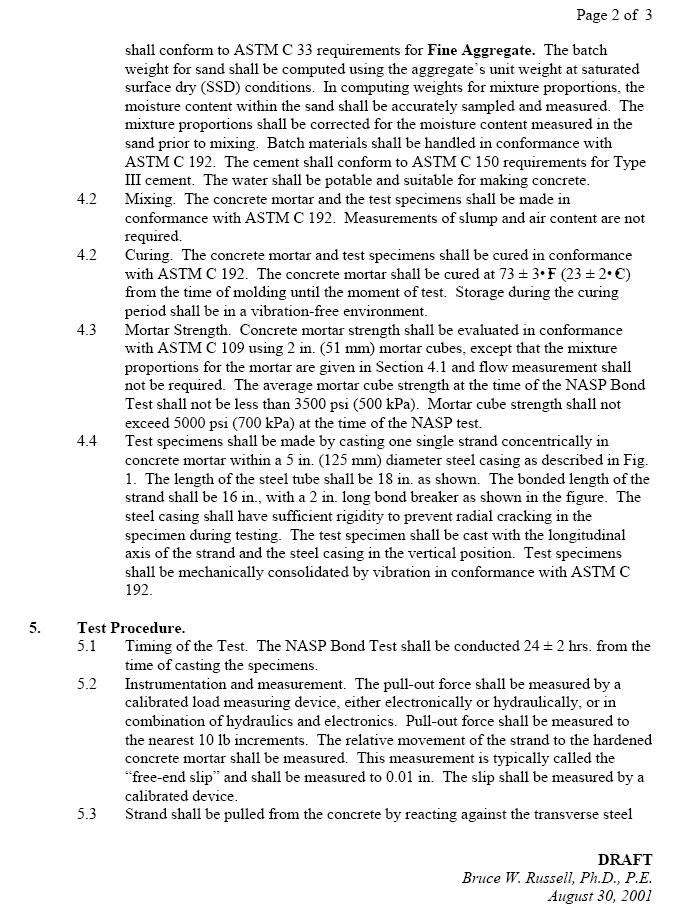
6 in the following proportions: 2 parts sand, 1 part cement and 0.45 parts water. The sand DRAFT Bruce W. Russell, Ph.D., P.E. May 20, 2004 shall conform to ASTM C 33 requirements for Fine Aggregate. The batch weight for sand shall be computed using the aggregate s unit weight at saturated surface dry (SSD) conditions. In computing weights for mixture proportions, the moisture content within the sand shall be accurately sampled and measured. The mixture proportions shall be corrected for the moisture content measured in the sand prior to mixing. Batch materials shall be handled in conformance with ASTM C 192. The cement shall conform to ASTM C 150 requirements for Type III cement. The water shall be potable and suitable for making concrete. 4.3 Mixing and Flow Rate. The concrete mortar and the test specimens shall be made in conformance with ASTM C 192. Measurements of slump and air content are not required. The flow should be measured according to the procedure described in ASTM C The recommended flow rate is between 100 and Consolidation. Concrete should be consolidated just enough to ensure perfect between strand and the surrounding concrete. 4.5 Curing. The concrete mortar and test specimens shall be cured in conformance with ASTM C 192. The concrete mortar shall be cured at 73 ± 3EF (23 ± 2EC) from the time of molding until the moment of test. Storage during the curing period shall be in a vibration-free environment. 4.6 Unit Weight of Mortar Cubes. Measure and record fresh unit weight of mortar cubes. In addition, unit weight of hardened cubes will be measured prior to testing under compression. 4.7 Mortar Strength. Concrete mortar strength shall be evaluated in conformance with ASTM C 109 using 2 in. (51 mm) mortar cubes, except that the mixture proportions for the mortar are given in Section 4.1 and flow measurement shall not be required. The average mortar cube strength at the time of the NASP Bond Test shall not be less than 4500 psi. Mortar cube strength shall not exceed 5000 psi at the time of the NASP test. If the minimum target value of 4500psi is not achieved, NASP testing will be performed regardless and the data should be reported. On the other hand, if mortar strength exceeds 5000psi, repeat the NASP test. 4.8 Test specimens shall be made by casting one single strand concentrically in concrete mortar within a 5 in. (125 mm) diameter steel casing as described in Fig. B.1. The length of the steel tube shall be 18 in. as shown. The bonded length of the strand shall be 16 in., with a 2 in. long bond breaker as shown in the figure. The steel casing shall have sufficient rigidity to prevent radial cracking in the specimen during testing. The test specimen shall be cast with the longitudinal axis of the strand and the steel I-6
7 casing in the vertical position. Test specimens shall be mechanically consolidated by vibration in conformance with ASTM C 192. DRAFT Bruce W. Russell, Ph.D., P.E. May 20, Test Procedure. 5.1 Timing of the Test. The NASP Bond Test shall be conducted 24 ± 2 hrs. from the time of casting the specimens. 5.2 Stiff test frame (as shown in Fig. B.2) or equivalent to stiff test frame (equivalent to stiff test frame means test frame without torsional restraint) should be used for the NASP Bond Test 5.3 Instrumentation and measurement. The pull-out force shall be measured by a calibrated load measuring device, either electronically or hydraulically, or in combination of hydraulics and electronics. Pull-out force shall be measured to the nearest 10 lb increments. The relative movement of the strand to the hardened concrete mortar shall be measured. This measurement is typically called the free-end slip and shall be measured to 0.01 in. The slip shall be measured by a calibrated device. 5.4 Strand shall be pulled from the concrete by reacting against the transverse steel plate. The loading shall be controlled by strand displacement measured at the point where the load is applied to the strand. The displacement rate shall be 0.1 in. per minute (2.5 mm per minute). 5.5 The strand shall be loaded at a distance approximately 6 in. from the end of the specimen. 5.6 The pull-out force shall be recorded when the opposite end of the strand, or the free end achieves a total displacement of 0.10 in. relative to the hardened concrete mortar. 5.7 If the hardened concrete mortar exhibits cracking in two or more of the six individual tests, then all results of NASP Strand Bond Test shall be discarded and new specimens prepared for a new NASP Strand Bond Test. 6. Reporting. 6.1 Sample Size. A single NASP Strand Bond Test shall consist of a minimum of six (6) individual tests conducted on single strand specimens. 6.2 For each individual test, report the pull-out force that corresponds to a relative displacement of 0.10 in. between the strand and the hardened concrete mortar. 6.3 For the NASP Bond Test, compute the average pull-out force from the individual tests and report the value as the average value for the NASP Bond Test. If one of the specimens exhibited radial cracking during testing, disregard the pull-out value of that specimen when reporting results. If two or more of the specimens exhibit radial cracking, the entire I-7
8 results should be disregarded and the NASP Bond Test performed again in its entirety. 7. Acceptance 7.1 The strand shall be accepted for pretensioned and post-tensioned prestressed applications when the average value of the NASP Strand Bond Test is not less than lbs and no individual test result is less than lbs. I-8

9 DRAFT Bruce W. Russell, Ph.D., P.E. May 20, 2004 Figure B.1. NASP Test Setup I-9

10 Figure. B.2. Typical Stiff Test Frame to Conduct NASP Bond Test I-10