1. DESIGN & CONSULTING SERVICES GLASS FIBER REINFORCEMENT PRODUCTS AT A GLANCE GFRP BAR
|
|
|
- Joseph Lindsey
- 5 years ago
- Views:
Transcription
1 1
2 1. DESIGN & CONSULTING SERVICES GLASS FIBER REINFORCEMENT PRODUCTS AT A GLANCE GFRP BAR DATA SHEETS (STRAIGHT BAR) STANDARDS& DESIGN GUIDES STORAGE, TRANSPORT & MACHINING STORAGE & TRANSPORT CUTTING BENDING CONNECTION TENSILE STRENGTH & E-MODULUS TRANSVERSE SHEAR STRENGTH CREEP RUPTURE (SUSTAINED LOADS) DURABILITY & ALKALI RESISTANCE BOND BEHAVIOR CRACK WIDTH DEFLECTION THERMAL BEHAVIOR COEFFICIENT OF THERMAL EXPANSION BEHAVIOR - AMBIENT TEMPERATURES BEHAVIOR - LOW TEMPERATURES FIRE RESISTANCE CONCRETE COVER & 90 MINUTE FIRE RATING DESIGN CONSIDERATIONS
3 1. DESIGN & CONSULTING SERVICES The engineers at RADYAB will gladly assist you on questions regarding structural design and building physics. Please contact them for assistance on your projects: Technical Service Telephone-hotline and technical project service Telephone: Telefax: and Website: 3
4 2. GLASS FIBER REINFORCEMENT GFRP BAR (composite rebar) belongs to the family of glass fiber composite materials, glass fiber reinforced polymer (GFRP) to be exact. GFRP consist of fibers of glass set in a resin matrix to form a rebar rod or grid or fibers. These reinforcement bars are installed in much the same manner as steel. The first known use of GFRPs as reinforcement occurred in 1975 in the former Soviet Union. Significant studies of using GFRP as reinforcement began in Europe in the 1980s. GFRP reinforcements gained significant support during the 1990s from research of magnetically levitated (maglev) train support structures in Japan. The Japanese in 1996 were the first to introduce design guidelines for GFRP reinforced concrete. Since then, the use of GFRP as structural reinforcement has increased exponentially and design guidance has been authored by organizations from around the world. Crucially till now, the high initial purchase cost has restricted its application. However, with GFRP BAR this is no longer the case as GFRP BAR is being offered at prices below steel reinforcement market price. When correctly applied, GFRP reinforced concrete structures have a great deal of advantages, in particular a dramatic reduction in problems related to corrosion, either by intrinsic concrete alkalinity or by external corrosive fluids that might penetrate the concrete. These structures can be significantly lighter and have a much longer service life of up to 100 years. In particular GFRP rebars are useful for structures where the presence of steel would not be acceptable. For example, magnetic resonance imaging (MRI) machines have large magnets, and accordingly require non-magnetic buildings. Also, where the design life of the concrete structure is important, GFRP reinforcing has its advantages where corrosion of reinforcing steel is a major cause of failure. In such situations corrosion-proof GFRP reinforcing will extend a structure's life substantially, for example in the marine structures. GFRP rebars will also be useful in situations where it is likely that the concrete structure may be compromised in future years, for example in all marine concrete capping beams or concrete sewage pipe lines where the service life of the structure is likely to be many times the service life of the waterproofing membranes or other anti corrosion measures. GFRP reinforcement is stronger, and has a much better strength to weight ratio than reinforcing steel. Also, because it resists corrosion, it does not need a protective concrete cover as thick as steel reinforcement does (typically 30 to 50 mm or more). GFRP reinforced structures therefore can be lighter and last longer. The material properties of GFRP bars differ markedly from steel, so there are differences in the design considerations. GFRP bars have relatively higher tensile strength but lower stiffness, so that deflections are likely to be higher than for equivalent steel-reinforced units. 4
5 Structures with internal GFRP reinforcement typically have an elastic deformability comparable to the plastic deformability (ductility) of steel reinforced structures. Failure in either case will occur by compression of the concrete rather than by rupture of the reinforcement. Deflection is always a major design consideration for reinforced concrete. Therefore, deflection limits are set to ensure that crack widths in steel-reinforced concrete are controlled to prevent water, air or other aggressive substances reaching the steel and causing corrosion. As there is no danger of corrosion, for GFRP reinforced concrete, aesthetics and possibly water-tightness will be the limiting criteria for crack width control. GFRP rods also have relatively lower compressive strengths than steel rebar, and accordingly require different design approaches for reinforced concrete columns. A potential limit to the use of GFRP reinforcement is the limited fire resistance. Where fire safety is a consideration, structures employing GFRP have to maintain their strength and the anchoring of the forces at temperatures to be expected in the event of fire. For purposes of fireproofing an adequate thickness of cement concrete cover or protective cladding is necessary. Therefore, it is not always possible to replace the reinforcing steel by GFRP BAR, because of the above said limitations and the fact that mechanical properties of the two materials differ. For example, E-modulus and shear strength of GFRP bars are lower, but the tensile strength is significantly higher than that of steel. Nevertheless, the applicabilities of the GFRP BAR reinforced elements are greater than their planning restrictions compared to steel reinforced elements. As such there is growing interest in application of GFRP composite rebar recognized by different countries and number of projects using composite rebar increases day by day around the world, ranging from USA, Russia, Japan, South Korea and Germany. 5


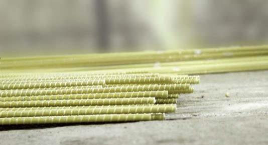
6 3. PRODUCTS AT A GLANCE 6

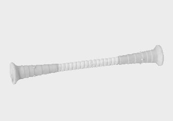
7 4.GFRP BAR The composite GFRP BAR now offers an entirely new range of applications in civil engineering. The reinforcing bar consists of a multitude of continuous fibers, oriented in the direction of the load, each with a diameter of approx. 20 μm. They are bonded in anepoxy resin matrix. Schematic of typical GFRP Bar constituents The fibers provide the longitudinal strength and stiffness of the material. The resin matrix holds the fibers in place, distributes the load and protects the fibersagainst physical& chemical damage. The standard GFRP BAR is a glass fiber reinforced round bar with surface ribbing. The product was conceptualized as plain reinforcement for concrete components. Its physical as well as its bond properties is comparable to those of reinforcing steel. This is achieved with the use of high quality components, the specialized production process and the unique, patented geometry of the ribs.they are certified for a design service life of 100 years. GFRP BAR is linearly elastic up to failure. For bar diameters of up to 25 mm diameter, it occurs at stresses well above 1,000 MPa. As a result of the comparatively low modulus of elasticity of GFRP BAR ( 55 GPa), the failure of GFRP BAR reinforced concrete members is preceded by large deflections. When the load is removed the deflection returns to near zero. GFRP BAR cannot be permanently deformed or bent. If a straight bar is bent it returns to its original shape as soon as the applied force is removed. Bars with small diameters can be bent elastically (circular tunnel cross-sections). Customized bent bars and stirrups may be prefabricated at the shop. 7


8 5. DATA SHEETS (STRAIGHT BAR) *Conservative design value of tensile strength (not yielding) The values listed in this table are determined at room temperature. 8
9 6. STANDARDS& DESIGN GUIDES USA ACI 440.1R-06 (2006) Guide for the Design and Construction of Structural Concrete Reinforced with FRP Bars, American Concrete Institute ACI 440.3R-04 (2004) Guide Test Methods for Fiber-Reinforced Polymers (FRPs) for Reinforcing or Strengthening Concrete Structures AASHTO GFRP-1 (2009) AASHTO LFRD Bridge Design Guide Specifications for GFRP-Reinforced Concrete Bridge Decks and Traffic Railings, American Association of State Highway and Transportation Officials. Canada CAN/CSA-S Specifications for Fiber-Reinforced Polymers. CAN/CSA-S Design and Construction of Building Components with Fiber- Reinforced Polymers. CAN/CSA-S6-06 (2006) Fiber-Reinforced Structures, Canadian Highway Bridge Design Code, pp Switzerland Fib Bulletin No.40 (2007) FRP Reinforcement in RC Structures. Japan JSCE Series 23 "Recommendation for Design and Construction of Concrete. Structures Using Continuous Fiber Reinforcing Materials." JBDPA Design Manual (2009) Japanese Design and Construction Guidelines for Seismic Retrofit of Building Structures with FRP Composites. Germany DIN EN-Concrete Reinforced and Pre-stressed Concrete Structures - Part 1: Design and Construction. AND EN (Europe) CNR-DT 203 &CNR-DT 205 (Italy) GOST (Russia) 9
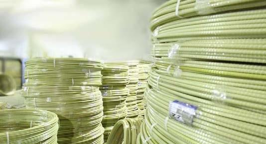
10 7. STORAGE, TRANSPORT & MACHINING STORAGE & TRANSPORT In general, high intensity long-term exposure to UV-rays can lead to the discoloration of polymers. After a prolonged (more than 6 months) exposure the surface of the material becomes brittle. Unless special protective measures are undertaken, this results in the lasting deterioration of the polymers. As a result, GFRP BAR should be covered and stored in a dry environment, especially when stored for longer time periods. Tests on bars that were stored outdoors for up to eight weeks without being protected showed that climatic exposure in Russia lead to a discoloration without causing a reduction of the bond or the tensile strength. To avoid damage to the ribs, the material should not be dragged on the ground. It should not be subjected to strong abrasive forces. When hoisted by crane, the deflection of GFRP BAR is similar to that of steel bars of equal diameter. It is important that the appropriate cross beam/lifting equipment is used at all times. CUTTING Cutting GFRP BAR is significantly easier than cutting steel rebar. Either a hacksaw, band saw, or a grinder, using a diamond or a tough metal disc, is recommended. Both are fine enough to achieve a clean cut. GFRP BAR should not be trimmed with bolt cutters or shears, as the glass fibers fray when the material is sheared off. If desired, grates at the bar ends can be removed with a file or a rasp. Because of the relatively low strength perpendicular to the glass fibers, GFRP BAR should not be subjected to impact forces. BENDING GFRP BAR is linearly elastic up to failure. It cannot be bent permanently (plastically). A bent bar returns to its original shape once the bending force is removed. Small diameter GFRP BAR can be bent into a radius as long as they are fixed in position while the concrete hardens. The stress induced in the bar by the bending process is to be added to the stress induced by the subsequently applied load. The total stress must not exceed the permissible value. GFRP BAR customized stirrups and bent bars may be pre-fabricated at the factory for larger orders. CONNECTION Reinforcement cages made of GFRP BAR are best assembled with ordinary tying or coated wire. Damage to the bars caused by properly installed tying wire is insignificant. 10
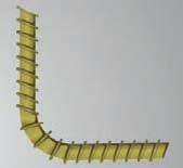
11 In cases where reinforcement cages are to be entirely free of steel, plastic wire ties, such as those used by electricians, can be used. A tightening wrench facilitates pulling and trimming of the ties. Plastic clips are under development and shall be available soon to connect GFRP BAR at ninety degree angles to form meshes. The clips may be affixed to the bars using a rubber hammer or a similar tool. On a solid surface the clips may even be affixed by stepping on them with shoes. Bar couplers, that are glued onto the GFRP BAR in the factory, are under development and shall soon be available. They are an alternative means of connecting GFRP BAR and steel bars. When the GFRP BAR is screwed onto the steel bars, it is important that they are handled and turned at the connector, not at the bar. The glued couplers should not be exposed to temperatures above 100 C. Special care needs to be taken when welding in the vicinity of the couplers. Wire rope grips can be used to connect GFRP BAR to steel reinforcing bars. The GFRP BAR should be placed in the curved form piece of the grip. Two short pieces of smaller diameter steel rebar should be placed in the grip, between the GFRP BAR and the steel bar, to minimize the damage to the GFRP BAR caused by the clamping force. 11
.")
12 8. TENSILE STRENGTH & E-MODULUS In contrast to steel, GFRP BAR behaves in a linear elastic manner up to failure. Yielding is not observed. The modulus of elasticity of straight bars is well above 55 GPA (60 GPA for ø 14 mm bars). The mean value of the short-term tensile strength measured in tensile tests on bare GFRP BAR lies between 1,000 MPa (large diameter bars) and well above 1,500 MPa (8 mm). The true value is much higher, as the fibers themselves have a tensile strength of more than 3,000 MPa. With the volumetric fiber content of approximately 80% GFRP BAR must have a short-term tensile strength of approx. 2,200 MPa. The measured values are much lower, as the bars fail prematurely at the clamped ends and due to internal stresses being induced in the bars during the tests (eccentricity, application of force along the bar circumference only, etc.). As the long-term strength of FRPs cannot be derived from their short-term strength, the meaning of the short-term values for structural designs is an best a nominal figure. To determine the tensile strength and the stress-strain relationship both ends of GFRP BAR are glued into shafts. The load is applied at approximately 1 kn/sec. in a hydraulic press. Up to a load of sixty percent of the ultimate load, the modulus of elasticity is determined using highly sensitive strain gages. Afterwards the load is increased until failure occurs. The results of one such test carried out in Russia on 8 mm diameter GFRP BAR per relevant GOST standards are displayed below: Failure was brittle. It occurred in the free span of the test specimen, when the tensile strength of the material was exceeded. The fibers burr in the fracture zone in a brush-like fashion. The 12

13 outermost bar ends, where the specimen is fixed in the hydraulic press, including the ribs of the bars, are undamaged.in contrast to the brittle failure of the test specimen, an GFRP BAR reinforced structural element behaves in a ductile manner. Distinct signs of the impending failure occur well in advance of the ultimate load. The tests have demonstrated that the measured short-tem tensile strength for all bar diameters is greater than 1,200 N/mm 2 and that the modulus of elasticity is 55,000 N/mm 2.The long-term strength of FRPs depends on both the maximum temperature and on the frequency and amplitude of the temperature changes whereto the bars are exposed.characteristic values (CSA S806) / specified values (CSA S CHBDC) of the tensile strength of GFRP BAR for typical design service live spans are listed in the table below: The values in the above table are characteristic values (as defined in CSA S806). These correspond to the specified tensile strength as defined in CSA S6-06 (CHBDC).To determine design values of the tensile strength these values are to be multiplied / divided by the appropriate safety or reduction factors specified in the relevant sections of the codes. 13
14 9. TRANSVERSE SHEAR STRENGTH The transverse shear strength of the GFRP BAR is frequently measured from random production runs in Russia. The testing is performed per ACI 440.3R test method B.4 and ASTM D7617. The property is consistent across bar diameters. The transverse Shear Strength is 200 Mpa. 10. CREEP RUPTURE (SUSTAINED LOADS) GFRP bars subjected to a constant load over time can suddenly fail after a time period called the endurance time. The endurance time is greatly affected by the environmental conditions such as high temperature, alkalinity, wet and dry cycles, freezing and thawing cycles. As the percentage of sustained tensile stress to short-term strength of the bar increases, the endurance time decreases. For this reason, the design limits on GFRP bars in consensus standards limit sustained loads on GFRP bars to very low levels of utilization. We recommend designers use the appropriate consensus guideline for creep rupture stress limits of GFRP BAR. 14
15 11. DURABILITY & ALKALI RESISTANCE One of the main concerns about the use of GFRP is its potential to be degraded in the long term by the high ph environment of the concrete itself. This phenomenon is analogous to an alkali silica reaction with certain types of aggregate. A great deal of research has been performed on this subject with the conclusion being that a properly designed and manufactured composite system of resin and glass can adequately protect the glass fibers from degradation. GFRP BAR is made from epoxy resin matrix and Alkali resistant Advantex glass fibers. Selection of high caliber raw materials, results in a good bond between the Advantex glass fiber itself and the protective resin and is key to successful long-term performance of the GFRP BAR. Current international codes and guidelines on GFRP reinforcement and the design of GFRP reinforced concrete structures require durability tests on the basis of a residual strength approach (CSA, ACI, GOST etc.). Bars are aged either under load or at relatively small loads (e 0.3 %) in an alkaline solution for specified periods of time. After the aging process the bars are unloaded. Their residual tensile strength is tested in conventional tensile tests. To characterize the long term properties of the GFRP BAR, rebar samples were subjected to a 0,1n (5%) solutions of potassium and sodium hydroxide per resistance value classification under GOST standard testing procedures in Russia. The resistance was evaluated by measuring swelling during exposure of samples in static condition at the ambient temperature (20+/-2) C for 14 days and at (80+/-5) C for 75 hrs. GFRP BAR achieved chemical resistance in excess of GOST Group 1 of chemical resistance (alkaline-resistant, no chemical destruction observed) to impacts of 0,1n alkali solutions at ambient and elevated temperatures. It is important to note that tensile modulus properties are typically not affected by the alkaline bath at elevated temperatures. Subjecting the GFRP bars to an aqueous, high ph solution at elevated temperatures is not intended to be a perfectly accurate measure of the long term residual properties of the GFRP bar, rather its purpose is to differentiate high caliber GFRP bars from lesser quality ones. The unlimited supply of free ions in the purely aqueous elevated ph solution are much more harmful than actual field conditions. This conclusion is drawn from a series of tests performed on GFRP bars extracted from service in several structures across Canada by the ISIS research network that reveals NO DEGRADATION of GFRP bars after being in service for eight to ten years. At this time, there is no consensus as to what would be an accurate service life prediction model for the use of GFRP bars. Links to the complete ISIS findings are available at the Radyab Company web site at
 laboratories in UAE.")


16 12. BOND BEHAVIOR To determine the bond behavior of GFRP BAR reinforcement, four eccentric pullout tests was performed on 150 x 200 x 200 mm concrete cubes, using two pairs of 6 & 8 mm bars according to the ACES (Arab Center for Engineering Studies) laboratories in UAE. The displacement at the unloaded end of the bar was plotted as a function of the load. The compressive strength of the concrete was > 40 N/mm 2. Pullout tests conducted in ACES Laboratories of UAE on 8 mm GFRP BAR. The results of the test series are: The failure mode is, as with steel rebar, extraction of the concrete corbels from the concrete block. The ribs of the rebar were largely undamaged. As is the case for reinforcing steel, higher bond stresses are observed in higher grade concrete. No significant differences were observed regarding the slip of the unloaded bar end of GFRP BAR and steel bars. The maximum bond stress was recorded at a slip between 10 mm and 15 mm. Even though the bond stress of GFRP BAR is greater at the same amount of slip, the tensile splitting forces are lower than those of steel rebar. 16
17 13. CRACK WIDTH The following approach can be taken to derive the approximately required cross sectional area of GFRP BAR crack reinforcement from the required amount of steel rebar.the crack width is proportional to the diameter of the rebar, independent of the reinforcing material, which is used. If more bars of a smaller diameter are installed the cracks will be smaller. As is the case for steel rebar, the total slip of GFRP BAR (pullout test) is proportional to the square of the stress in the bar. If the stress is reduced by half, the slip decreases to 25%. It can be conservatively assumed that the crack spacing is the same in a member reinforced with GFRP BAR as it is in a steel reinforced section. Based on these facts and assumptions the relationship between the required amount of GFRP BAR and the required amount of steel rebar is: For equal bar diameters this implies: However, it is important to point out that due to the non-corrosive nature of GFRP BAR there is no danger of corrosion induced concrete failure and the crack width limit tolerated may be much larger than that of a steel reinforced concrete structure. As for GFRP BAR reinforced concrete, aesthetics and possibly water-tightness will be the limiting criteria for crack width control rather than corrosion. 17

.")
18 14. DEFLECTION As noted earlier, the modulus of elasticity of GFRP BAR is low compared to steel rebar (EF= 55GPa). Therefore, special attention needs to be devoted to checking the serviceability limit state requirements.in a test at ACES (Arab Center for Engineering Studies) laboratories in UAE test four concrete slabs of identical dimensions (1,100 x 1,50 x 150 mm), were tested in a four point bending test (bending zone without shear: 1,000 mm). Slabs 1 and 2 were reinforced with two numbers ofø 8 & ø 6 mm steel rebars (grade A-III) respectively, while slabs 3 and 4 with two numbers of ø 8 & ø 6 mm GFRP BAR respectively. The position and distribution of the bars were identical. The maximum load sustained by the GFRP BAR reinforced slabs was more than twice as high as the load sustained by the steel reinforced slab of equal diameter. The maximum deflection was about three times as high. After the first cracks the deflection of all slabs were nearly identical. After the service load was reached the deflection of the GFRP BAR reinforced slabs was about higher than that of the steel reinforced member. Conclusion In any design of GFRP reinforced concrete members special attention needs to be paid to checking the deflection requirements. 18
19 15. THERMAL BEHAVIOR COEFFICIENT OF THERMAL EXPANSION The Coefficient of Thermal Expansion of GFRP bars is an inherent characteristic property and if sufficient concrete cover of 2db or 30 mm (whichever is greater) is used, it is not an important design consideration. This is because there is not enough radial force to cause reflective concrete cracking if adequate concrete confinement is present. These findings are elaborated in the work of Aiello, Focacci & Nanni in ACI Materials Journal, Vol. 98 No. 4, July-Aug 2001, pp Effects of Thermal Loads on Concrete Cover of FRP Reinforced Elements: Theoretical and Experiential Analysis. Therefore, structural elements reinforced with GFRP BAR are not affected by temperature changes. Furthermore, expansive cracking did not occur in lab experiments in Russia, even when GFRP BAR reinforcing bars were placed close to the surface of the specimen and the moisture content was varied over time. The radial coefficient of thermal expansion was determined on test specimen at temperatures ranging from 0 C to 70 C. From these tests, the coefficient of thermal expansion for GFRP BAR was determined to be 9-12 x For comparison the coefficient of thermal expansion of concrete is between 0.5 and 1.2 x 10⁻⁵, that of reinforcing steel is 1.0 x 10⁻⁵, that of stainless steel 1.5 x BEHAVIOR - AMBIENT TEMPERATURES The ambient temperature of a structural element reinforced with GFRP BAR should not ideally exceed 70 C. However, it is important to note that structure temperatures of up to 100 C may be tolerated for short time spans. Unless noted otherwise, all technical values specified in the product data sheet were determined at room temperature. Please contact the technical services at RADYAB Engineering in case GFRP BAR is to be installed in structural elements that will be exposed to increased temperatures over longer time spans. BEHAVIOR - LOW TEMPERATURES The behavior of GFRP BAR was tested at extremely low temperatures up to minus forty degrees centigrade (-40 C) in various test series in Russia. It was shown that the material properties of GFRP BAR remain nearly unchanged at extremely low temperatures. 19
20 16. FIRE RESISTANCE The resins used in the production of GFRP BAR withstand temperatures up to about 200 C over short time spans. The glass fibers soften at about 600 C. GFRP BAR can catch on fire when exposed to an open flame. After a few seconds the bars stop burning, when no more flammable material remains on the surface of the bars. GFRP BAR does not contain fireresisting additives. In case an increased fire resistance of GFRP BAR -reinforced structural elements is required, non-structural measures, such as an increase of the concrete cover or an encasement with fireresistant material, are recommended. Most fire protection methods customary to conventionally reinforced concrete construction can be applied. CONCRETE COVER & 90 MINUTE FIRE RATING The isothermal lines for concrete also apply to GFRP BAR reinforced elements. The critical temperature of GFRP BAR is 350 C. When GFRP BAR are installed in a member with a 30 Minute fire rating the required concrete cover is 30 mm. For a 90 Minute fire rating the required concrete cover for GFRP BAR is 65 mm. Values for other fire ratings can be interpolated or determined using the isothermal lines of the specific concrete used in the member. Wherever possible, GFRP BAR reinforced members should be protected against fire by applying fire coatings or by encasing the concrete member in fire cladding. These measures result in an overall more economical structure. 20
21 17. DESIGN CONSIDERATIONS On the basis of through investigation and the information summarized in the product data sheet, structures can be designed with GFRP BAR reinforcement according to accepted regulations and codes, such as ACI 440.1R-6 (USA), CSA-S (Canada)or DIN (Germany) if the following issues are taken into consideration. 1. GFRP BAR is conceptualized as plain reinforcement for concrete construction. For material properties concrete please refer to current national codes. Material properties of GFRP BAR are listed on under Section. 6 of this technical information.loads may be determined in accordance with current national codes. 2. GFRP BAR behaves linearly elastic up to failure. Yielding is not observed. Plastic hinges do not form. As a result, the loads on GFRP reinforced concrete elements cannot be determined using plastic limit analysis. As cracked sections transfer increasingly larger loads, moment redistribution is observed only to a very limited extent in GFRP BAR reinforced concrete members. Moment redistribution should, therefore, not be considered in the design. For safety reasons non-linear material properties should not be considered in the design. They may be considered in the analysis of members and in the determination of deflections. 3. We recommend that, for long-term application, the characteristic tensile strength be determined according to the data presented in Section. 9 of this technical information sheet. Alternatively a conservative maximum allowable stress at the ultimate limit state (ULS) may be set at435 N/mm GFRP BAR is not corrosive. As a result a concrete cover of ds + 10 mm in accordance with DIN , is recommended for all exposition classes. The reduced value of ds + 5 mm can be applied for precast elements. Alternatively per Canadian CSA S the minimum clear concrete cover in reinforced concrete members shall be 2db or 30 mm (whichever is greater). 5. The long-term deflection and bond creep of GFRP BAR is comparable to those of steel rebar. 6. The modulus of elasticity of GFRP BAR is substantially less than that of steel rebar. As a result, the behavior in the serviceability limit state is often more critical in the design than it is in steel reinforced concrete members. 7. Development lengths of straight GFRP BAR are to be determined according to the relevant international codes. Ideally the development length of straight bars may be reduced by installing a bar with a headed end. GFRP BAR headed ends are currently under development to be used as shear reinforcement in slabs and beams. They will be designed to transfer loads at minimal slip. Stirrups or bent bars are also possible. 21
22 8. GFRP BAR has an estimated compressive stress of 400 N/mm 2. However, due to the lack of experimental data ACI and CSA still do not recommend usage of GFRP bars in compressive elements. We therefore, discourage the use of GFRP BAR bars as compression reinforcement. 9. The coefficient of thermal expansion is compatible with that of concrete. Neither cracks nor other signs of damage due to temperature-induced volume changes have been observed in structural elements reinforced with GFRP BAR. 10. The long-term ambient temperature of elements reinforced with GFRP BAR should not exceed 70 C although temperatures as high as 100 C may be tolerated for short time spans. The elevated temperatures during curing of massive concrete elements do not cause any harm to the material. A reduction of the strength of the material was not observed. 11. A fire rating of GFRP BAR is not yet available. In case fire resistance of GFRP BAR -reinforced structural elements is an issue, nonstructural fire proofing measures, such as an encasement with fireboard, should be considered. The same methods as those used on conventionally reinforced concrete structures can be considered. For more information refer to Section Lap lengths of GFRP BAR are designed and executed in the same manner as splices of conventional steel rebars are. However, due to differing bond properties, it is generally advised to use a splice length twice as that required for steel. 13. Due to the comparatively low modulus of elasticity of GFRP BAR, special attention needs to be paid to the control of the deflection and the crack width.crack widths of more than 0.7mm (internal members) and 0.5mm (exterior members) may be tolerated depending on applications. As for GFRP BAR reinforced concrete, aesthetics and possibly water-tightness will be the limiting criteria for crack width control rather than steel corrosion or concrete durability. 22