MEMORANDUM. TO: STUART OLSON DOMINION CONSTRUCTION LTD. DATE: JANUARY 31, 14 ATTENTION: MR. Dave Bauder, Construction Manager KENNY K. C.KO, P.ENG.
|
|
|
- Irene Higgins
- 5 years ago
- Views:
Transcription
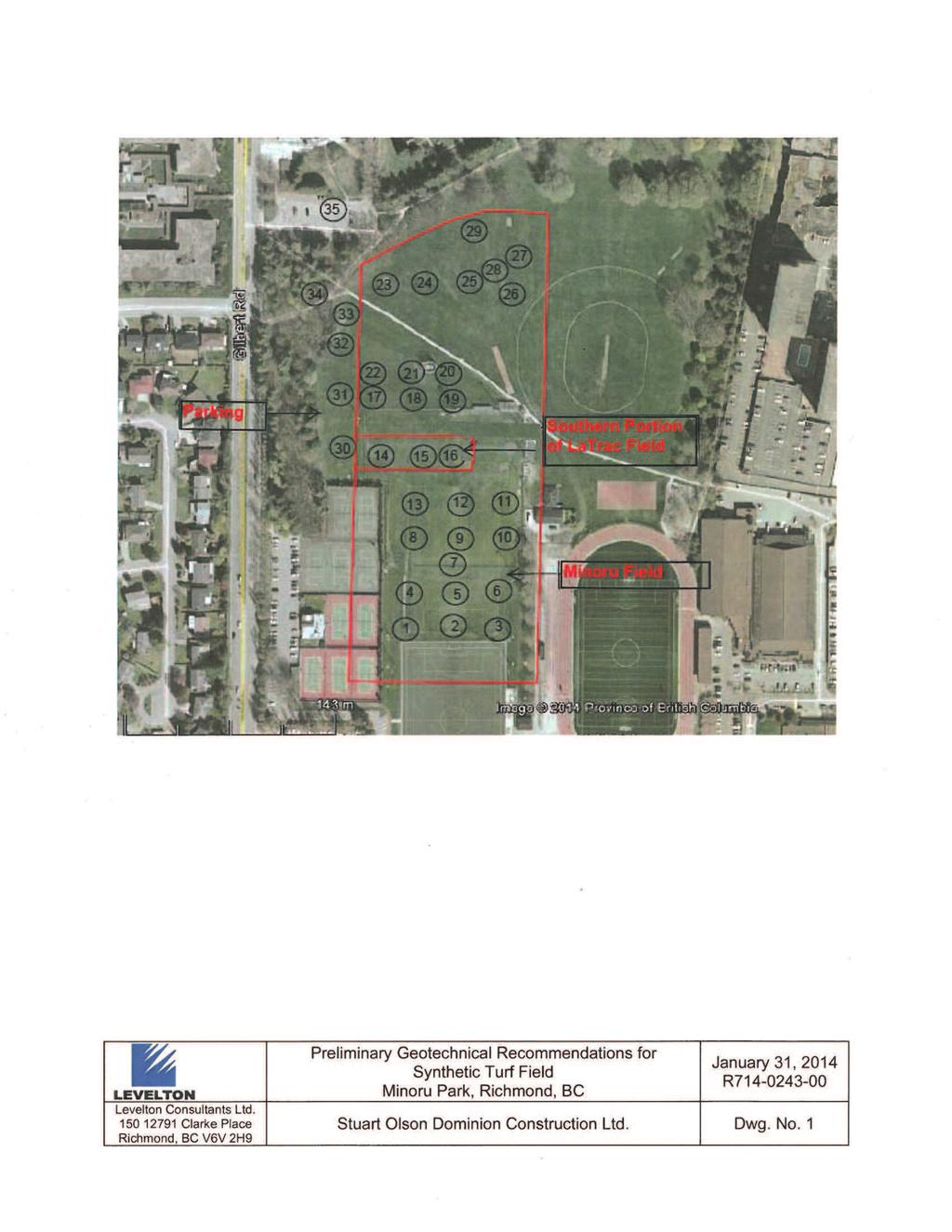
1 MEMORANDUM Levelton Consultants Ltd Clarke Place Richmond, BC V6V 2H9 Canada Tel: Fax: Web Site: TO: STUART OLSON DOMINION CONSTRUCTION LTD. DATE: JANUARY 31, 14 ATTENTION: MR. Dave Bauder, Construction Manager FROM: HESHAM DIEF, PH.D., P.ENG. KENNY K. C.KO, P.ENG. PROJECT: PRELIMINARY GEOTECHNICAL RECOMMENDATIONS FOR SYNTHETIC TURF FIELDS, MINORU PARK, RICHMOND, BC FILE: R This memorandum summarizes our preliminary recommendations for the proposed synthetic turf fields to be developed at Minoru Park in the City of Richmond. These recommendations will be presented in details in a Geotechnical Report later. 1.0 SOIL AND GROUNDWATER CONDITIONS The recent field investigation completed by Levelton consists of ft. deep machineaugered test holes, located within the proposed synthetic turf fields at Minoru 2 and La Trace and the parking area to the west of the La Trace Field as shown on the attached Dwg. No. 1. All draft test hole logs are attached. The site is generally covered with grass. In general, the test holes at Minoru 2 field and the southern portion of La Trace field encountered 1.5 to 2.5 ft. of river sand fill covering 1 to 3 ft. of pea gravel fill covering 4.5 to 6.5 ft. of native clayey silt underlain by loose sand extending down to over 20 ft. depth as shown in AH14-01 to AH A 1 ft. thick layer of organic sandy silt, peat/ topsoil layer was encountered below the pea gravel fill layer at a depth of about 3 ft. below surface grade at AH The presence of these organic soils appears to be confined to a localized area. At other test locations within the La Trace field and the proposed parking area (AH14-17 to AH14-34), the test holes are generally encountered 2 to 3 ft. of random fill consisting of mixed organic clayey silt and silty sand, trace gravel, wood debris and brown/black topsoil covering 5 to 7 ft. of native clayey silt underlain by loose sand extending down to over 20 ft. depth. The groundwater level could not be readily determined during drilling, due to the relatively low permeability at the site soils. Based on our experience of Richmond, we expect that the groundwater table would be in the order of 3 ft below existing grade surface. However, we anticipate that the groundwater table at the subject site fluctuates seasonally.
2 STUART OLSON DOMINION PAGE 2 JANUARY 31, 2014 ATTENTION: MR. DAVE BAUDER FILE: R LONG-TERM SETTLEMENTS The loads from the proposed turf including base and sub-base fill will cause long-term settlements across the field area. Since the design grades of the fields have not yet been established, we have assumed that the design grade could be raised up to 1.5 ft. above present surface grades. On this basis, the total post-construction settlement in the proposed turf areas is expected to be in the order of 2 inches, and the differential post-construction settlement is expected to be in the order of 1 inch over a horizontal distance of 30 ft. These settlement estimates are based on assumed loads typical for the type of construction proposed. The post-construction settlement can be minimized by preloading, which involves placing a temporary fill load above the design finished grade for a period of approximately three weeks. The height of the preload should be 4 ft. as measured from the design finished grade. In order to reduce the volume of imported fill for preloading, preloading can be undertaken in multiple stages provided that there is an overlap of about 20 ft between stages. 3.0 CONCEPTUAL SITE PREPARATION We consider that the following site preparation would be appropriate for the subgrade of turf fields (see Dwg. No. 1): It is assumed that the artificial turf sports field development could involve raising the site grade by up to 1.5 ft. Site preparation for Minoru 2 field and the southern end of La Trace field should consist of the removal of vegetation to expose the river sand fill, and the exposed sand fill layer should be compacted and proof-rolled using a minimum 4 ft. diameter vibratory drum roller to a minimum of 98% of the material s Standard Proctor Maximum Dry Density (SPMDD), before placing sub-base fill layers (specified by others). Buried topsoil may be present at the north portion of Minoru 2 field (might be extended around AH14-12). Shallow test pits should be completed to delineate zones of buried topsoil. Any grade restoration that will be required should be completed using engineered fill compacted in lifts. We recommend that the imported engineered fill, which is required to backfill any excavated area to subgrade level, consists of a minimum of 1 ft. of well-graded 3 inch minus pit run sand and gravel containing less than 5% fines (material passing the sieve #200) by weight, or an alternate material approved by the Geotechnical Engineer prior to delivery to the site. Site preparation for La Trace Field and the proposed parking area should consist of the removal of vegetation, topsoil, existing organic fill and any disturbed/softened surficial soils to expose the native soft to firm clayey silt soils. Stripping depths to remove the surficial topsoil/organic fill are expected to be on the order of 2 to 3 ft. based on the auger holes, but may be greater or less in localized areas. The native clayey silt subgrade will be subject to softening and weakening if disturbed or exposed to surface water, therefore, stripping and excavation should be conducted using an excavator fitted with a smooth-mouthed cleanup bucket that progressively retreats from the stripped area as it excavates. Construction traffic should not travel directly on the exposed subgrade. For temporary construction vehicle access, we recommend that the clay subgrade be covered with at least 1.5 ft thick working surface of 3 inch minus sand and gravel in construction traffic areas to protect the subgrade from disturbance.
3 STUART OLSON DOMINION PAGE 3 JANUARY 31, 2014 ATTENTION: MR. DAVE BAUDER FILE: R The topsoil and existing random fill that are to be excavated from the proposed turf fields and parking areas are not considered to be suitable for re-use as engineered fill. 4.0 DRAINAGE The successful performance of synthetic surfaced athletic fields is usually associated with drainage. It is understood that the nature and the design of the artificial turf field above the prepared subgrade, including drainage, surfacing, base and sub-base fill layers and lining are beyond the scope of the geotechnical work for this project and are to be addressed by consultants who have the expertise in this component of work. It is anticipated that perforated drains will be required at designated intervals on the top of the native clayey silt. Typically, the drains should be surrounded with 6 inch of drain rock, wrapped in a non-woven geotextile filter cloth. The intervals at which the drains should be installed should be determined by the consultants who will be designing the turf fields and drainage system. It is anticipated that low permeability rates will generally be characteristic of the native firm to soft clayey silt deposits such that these deposits should not be relied upon to assist in field drainage. Overlying pea gravel that underlies the site is expected to attain high permeability rates but it was not located in all the test holes. Review of the permeability rates of overlying river sand fill is beyond the present scope of work for this project however to assist in the drainage design, at this preliminary stage, based on local experience with similar soils, its coefficient of permeability is predicted to be typically in the order of 6 x 10⁻⁵ m/sec. Based on experience, permeability rates of river sand will be highly dependent on the gradation of the material and the compactness of the material at the time it is tested and it could be measured in the field. 5.0 LIGHT POLE FOUNDATION It is anticipated that the overturning moment due to the wind load on the proposed light posts (if required) will govern the foundation design of the lighting system masts. Overturning of the light masts due to wind load will be primarily resisted by the passive resistance of the soil. The high mast lighting poles to be supported on piles in the order of 40 ft. long. The geotechnical design evaluations are based on using of 20 inch diameter concrete filled steel pipe piles with a 0.5 inch wall thickness, driven open-ended. Evaluation of the behaviour of the piles should be based on a maximum factored passive pile resistance of 25 kips for an individual pile, where pile deformations are to be kept in the range of ¼ inch. Levelton can assist the design team if required by providing the anticipated pile lateral resistance once pile design details become available. The available data suggests that the loose to compact sand soils under the native clayey silt are expected to undergo liquefaction under the 2,475-year earthquake. Post-liquefaction settlement would be in the order of 1 ft, and horizontal displacements would be in the order of 2 ft. The piles must be designed to withstand any potential ground movements.

4 STUART OLSON DOMINION PAGE 4 JANUARY 31, 2014 ATTENTION: MR. DAVE BAUDER FILE: R ON-SITE ASPHALT PAVEMENT Site preparation in the proposed asphalt areas should consist of the removal of random fill. Based on the boreholes general stripping is required in the associated driveway and surface parking areas to depths of about 2 to 3 ft. is required. We recommend the following pavement structure for on-site parking areas and driveways: 3 inch of asphalt, underlain by 6 inch of ¾ inch minus crushed gravel base course, underlain by 8 inch of 3 inch minus free-draining sand and gravel sub-base course. Backfill to subgrade level using engineered fill and compact to a minimum of 98% of the material s Standard Proctor Maximum Dry Density (SPMDD) before placing sub-base fill layers. It is recommended that the subgrade in areas that will be paved be surficially compacted with a large, smooth drum vibratory roller and then proof-rolled with a loaded dump truck under the review of the Geotechnical Engineer prior to placement of the sub-base course material. Areas that exhibit excessive deflection or rutting should be excavated and grade reinstated with additional sub-base course material. The sub-base and base courses should be compacted to not less than 100 percent of their SPMDD. HD/KCK/mg
5
6 T R
7 T R
8
9 T R
10 T R
11 T R
12 T R
13
14 T T R
15 T R
16
17 T R
18 T T R
19
20 T R
21 T R
22 T R
23 T R
24 T R
25
26 T R
27 T R
28
29 T R
30 T R
31 T T R
32 T R
33
34 T R
35 T R
36 T R
37 T R
38 T R
39 T R
40 T R