TRANSFORMER 150' SETBACK FROM 98' CONTOUR LAWN PLANTER PLANTER TEMPORARY BENCHMARK SPIKE 26" BASSWOOD ELEV.=139.36' PLANTER EXISTING 12" CMP
|
|
|
- Scot Nigel Knight
- 5 years ago
- Views:
Transcription
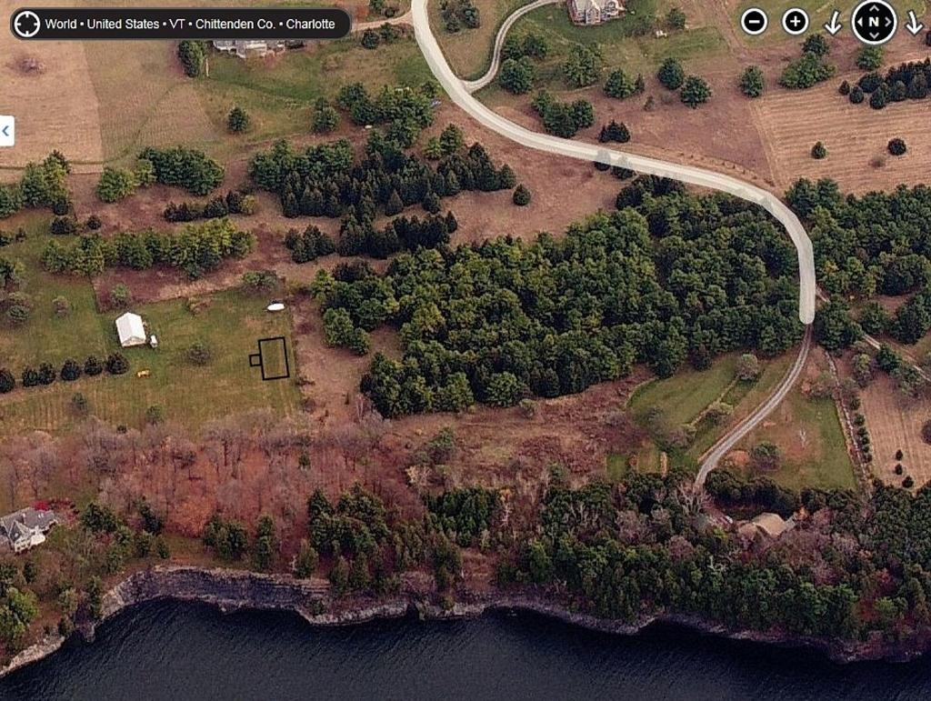
1 96 ST SHED TRANSFORMER C E A DECK UNDERGROUND LP TANK ' SETBACK FROM 98' CONTOUR LAWN GARAGE F.F.= NG MAB P:\AutoCADD Projects\2013\13229\1-CADD Files-13229\Dwg\13229-Site.dwg, 11/3/ :15:17 AM, aloiselle LAKE CHAMPLAIN Drilled Well Serving 1 Home - Up Slope of Disposal Field Drilled Well Serving 1 Home - Down Slope of Disposal Field Shallow Well or Spring, Up Slope of Disposal Field Shallow Well or Spring, Down Slope of Disposal Field Lakes, Ponds and Impoundment Rivers, Streams Drainage Swales, Roadway Ditches Municipal Water Main Service Water Lines EDGE OF LAKE Roadways, Driveways, Buildings ELEV= 95.0± Top of embankment or slope > 30% Property Line Trees Replacement Area Foundation, Footing Drains LEGEND 98' CONTOUR FIELD LOCATED MINIMUM ISOLATION DISTANCES (CONTACT ENGINEER FOR ANY CLARIFICATIONS OR CONFLICTS) Basis of Design Design Flow 5-BR Home Total Flow Horizontal Distance (Feet) Leach field Septic Tank Sewer 0 (Min.) 200 (Min.) 1 (Min.) 0 (Min.) ( Downslope) 35 (75 Downslope) 1. Isolation distances to well locations may vary due to site conditions - contact Engineer for verification with the Vermont Water Supply Rule Regulations. 2. For mound disposal systems, the limit of mound fill must be feet from any downhill property line and feet from side or uphill property lines. 3. If a curtain or foundation drain is downslope of the leach field, the leach field cannot be closer than 75 feet to the drain. If the drain is upslope of the leach field, it shall be 35' if possible and 20' minimum. 4. Sewers under roads, driveways or parking lots may require protective conduits or sleeves. 560 GPD 560 GPD Performance Based Design Approach Limiting Soil Condition - Fine Sandy Loam Limiting Slope Condition - 5.0%± Linear Loading Rate GPD/LF/VLF Design Trench - 8-foot Seepage Bed Standard Effluent Application Rate = 1 GPD/SF Design Linear Loading Rate GPD/LF Resulting Groundwater Mounding 6.3 See Hydrogeologic Study Required Separation to Mounded SHGWT = 36 Min. Required Depth of Sand under Bed = 22.5 Disposal Field Min Required Length of Bed 560 GPD / (6.22 GPD/LF) = 90 feet Limiting Percolation Rate = See Above Required Effective Basal Area = 560 GPD/(0.74 GPD/SF) = 757 SF Basal Area Provided = 1,779 SF Separation Distance to Property Line FT to Toe, 17 FT provided > 400 FT. provided FT to bed, 213 FT provided Required Separation to Bedrock = 4 FT, 6 FT min. provided Pressure Distribution System Minimum Required Number of Orifices 90 LF Bed x 6.3 FT width / ( GPD/SF) = 22.7 Use 23. Provide Two 1.5 Distribution Pipes, 86 FT long See Detail for Orifice Sizing and Layout Fill Volume of Distribution Piping = 16.2 Gal Minimum Required Dose Volume = 16.2 Gal x 5 = 81 Gal Minimum Number of Doses per Day = 4 Maximum Dose Size = 560 GPD/4 = 140 Gal APPROIMATE LOCATION OF WASTEWATER SYSTEM LAWN C.O. INV.=133.8 DECK LAWN PORCH F.F RESIDENCE F.F.= PATIO FM S NEW 4" SDR 35 PVC SEWER LINE (360LF) AVG S= (MIN S=0.0208) Pump Sizing = Invert of Distribution Piping in Mound (or High Pt of FM) = Low Elevation in Pump Station (FT) 34.5 = Elevation Head (FT) Length of SDR 26 PVC Force Main = 530 FT Diameter of Force Main = 2 Design Flow Rate = 28.7 GPM Friction Loss per 0 LF = 1.7 FT 8.96 = Resulting Friction Head (FT) 34. = Elevation Head (FT) 3.0 = Minor Losses (FT) 3.0 = Design Residual Pressure (FT) = Design TDH Use Hydromatic SHEF, 1 Ph, 60 Hz, 230 V, 0.5 HP or approved equal Pump Station Emergency Storage Required=630 GAL, 630 GAL Provided Septic Tank Minimum Size Required = 1,000 Gal for Design Flows <667 GPD GAL proposed Effluent Filter Required C.O. INV.= E EDGE OF GRAVEL ROAD W W W C.O. INV.=142.5 W E E E E FM FM FM S S S C.O. INV.=145.6 NEW 4" SDR 35 INV.= C.O. INV.=152.0 LAWN NEW 2" SDR 26 FORCE MAIN NEW 3/4" HDPE WATER SERVICE TO PROPOSED BARN 12" CMP INV=141.3 APPROIMATE LOCATION OF WATER LINE AND UNDERGROUND ELECTRIC TO BARN. LOCATION BY OWNER FM W W NEW ELEC. SERVICE TO PROPOSED BARN NEW 2" SDR 26 FORCE MAIN (530 LF) PROPOSED BARN LOCATION F.F. ELEV.=161.0 TEMPORARY BENCHMARK SPIKE 26" BASSWOOD ELEV.=139.36' RELOCATED 1" HDPE WATER & ELECTRICAL SERVICE E E W W " SHGWT 34" LEDGE FM W 8" HDPE INV.=151.4 B 14" SHGWT NO LEDGE 14" SHGWT NO LEDGE ' MIN. 8" HDPE INV.= " SHGWT 48" LEDGE RETAIN WATER SERVICE TO BARN 28" SHGWT 48" LEDGE THREASHOLD CONC. = A 160 ' MIN AREA NO DISTURBANCE " SHGWT NO LEDGE " SHGWT NO LEDGE " CMP INV= B " SHGWT NO LEDGE 18" SHGWT NO LEDGE " SHGWT 26" LEDGE A NEW MOUND DISPOSAL SYSTEM 6.3' 90' DISPOSAL BED 675 SF OF SURFACE AREA PROVIDED 162 TILLER 23.5 ± ACRES PERC TEST INFORMATION PT#1 PT#2 3.4 MIN/INCH 3.2 MIN/INCH Project Test Pitting November 2, 2014 Dave Marshall, Jim Huntington, John Patnaude TP#20 0-5" Loose Dark Brown Fine Sandy Loam - GR2 5-" Loose Brown Loam - PL3-18" Loose Dark Brown Loam - PL " Compact Grey Brown Silty Gravel 24-46" Medium Compact Grey Brown Gravel w/ Cobbles SHGWT 12" Roots to 18" Seeps at 41" No Ledge TP#21 0-6" Loose Brown Very Fine Sandy Loam - GR2 6-13" Loose Light Brown Very Fine Sandy Loam, Stony - GR " Medium Compacted Light Brown Fine Sandy Loam - GR " Compact Grey Brown Very Fine Silty Loam 32-46" Loose Grey Brown Loamy Gravel SHGWT 19" Roots to " No Seeps No Ledge Drawing Water from Lake TP#22 0-6" Loose Dark Brown Very Fine Sandy Loam - GR2 6-12" Loose Brown Very Fine Sandy Loam - BK " Medium Compact Brown Stony Loam- BK " Medium Compact Grey Brown Gravelly Loam 26-54" Loose - Compact Grey Brown Gravelly Loam SHGWT " Roots to 27" Seeps at " No Ledge (26" at east end) TP#23 0-5" Loose Dark Brown Loam - GR2 5-18" Loose Grey Brown Loam - PL " Medium Compact Grey Brown Stony Loam 26-48" Loose Compact Grey Brown Gravelly Loam SHGWT 14" Roots to 14" Seeps at 44" No Ledge TP#24 0-8" Loose Brown Loam - GR2 8-16" Loose Grey Brown Loam - PL " Medium Compacted Grey Brown Stony Loam SHGWT " Roots to 14" No Seeps Ledge at 34" TP# 0-7" Loose Brown Very Fine Sandy Loam - GR2 7-14" Loose Dark Brown Very Fine Sandy Loam - GR " Loose Grey Brown Loam - PL " Medium Compact Grey Brown Gravelly Loam SHGWT 14" Roots to 14" Seeps at 47" No Ledge TP#26 0-8" Loose Dark Brown Fine Sandy Loam - GR2 8-17" Loose Brown Gravelly Fine Sandy Loam - GR " Medium Compact Brown Stony Very Fine Sandy Loam - GR " Medium Compact Grey Brown Gravelly Fine Sandy Loam 35-51" Loose Grey Brown Stony Gravelly Fine Silty Loam SHGWT 28" Roots to 22" No Seeps Ledge at 48" TP#27 0-7" Loose Brown Very Fine Sandy Loam - GR2 7-17" Loose Dark Brown Very Fine Sandy Loam - GR " Loose Brown Sandy Loam - PL " Loose Grey Brown Stony Loam 40-49" Loose grey Brown Gravel SHGWT 27" Roots to 30" Seeps at 46" No Ledge TP#28 0-8" Loose Dark Brown Very Fine Sandy Loam - GR2 8-20" Loose Brown Stony Very Fine Sandy Loam - GR " Compact Brown Stony Loam 27-33" Loose Grey Medium Sand 33-56" Medium Compact Gravel and Cobbles SHGWT 18" Roots to 23" Seeps at 52" No Ledge TP#29 0-7" Loose Brown Very Fine Sandy Loam - GR2 7-20" Loose Grey Brown Very Fine Sandy Loam - GR " Medium Compact Brown Stony Loam 33-48" Loose Grey Stony Gravel SHGWT 18" Roots to 22" No Seeps Ledge at 48" JLM JLM THOMAS & MICHELLE TILLER PROJECT LOCATION LOCATION MAP FEB., " = 30' HOLMES ROAD CHARLOTTE VERMONT THOMAS & MICHELLE TILLER 362 HOLMES ROAD CHARLOTTE VERMONT 1" = 2000' WASTEWATER DISPOSAL SYSTEM SITE PLAN C1.1
2
3
4
5
6
7
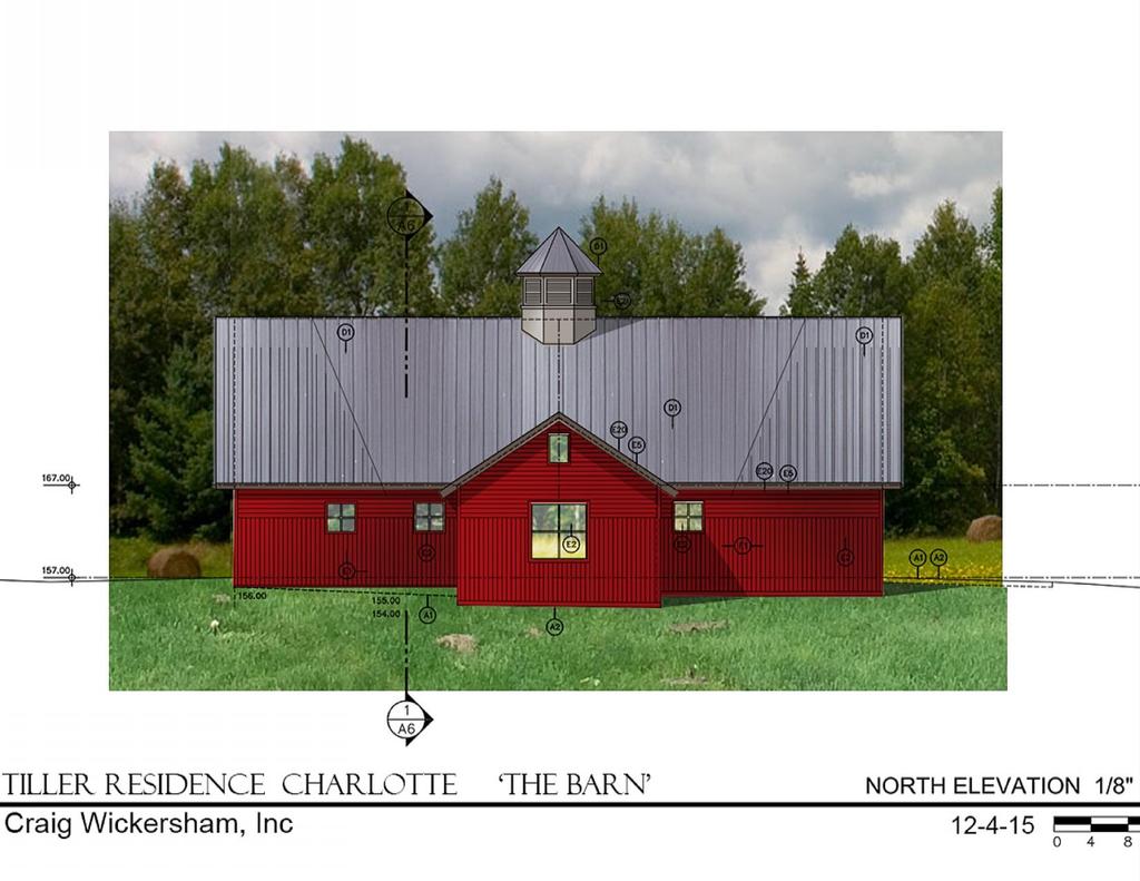
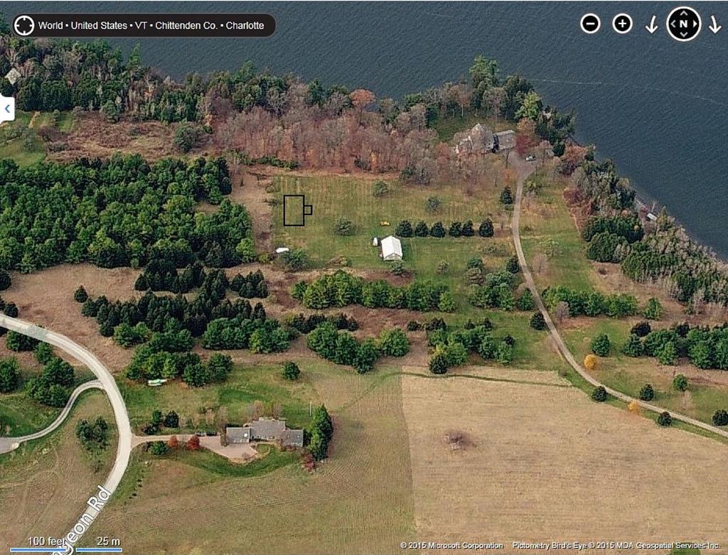
8 96 C E A n/f BARNES LAKE CHAMPLAIN 94 1' FROM OHW ' ± MAB 96 0 JLM JLM 5-BR HOME TO BE REMOVED PAVEMENT SURFACE TO BE REMOVED LEGEND THOMAS & MICHELLE TILLER 362 HOLMES ROAD CHARLOTTE VERMONT APPROIMATE LOCATION OF WASTEWATER SYSTEM TO BE TAKEN OUT OF SERVICE PAVED DRIVEWAY PROPOSED BUILDING LAKE CHAMPLAIN TILLER 23.5 ± ACRES 591' ± n/f MASLOW THOMAS & MICHELLE TILLER 362 HOLMES ROAD CHARLOTTE VERMONT 1' FROM OHW 98.0 NEW EDGE OF WOODS WELL ISOLATION AREA EDGE OF LAKE ELEV= 95.0± BARN GENERAL NOTES 1. Utilities shown do not purport to constitute or represent all utilities located upon or adjacent to the surveyed premises. Existing utility locations are approximate only. The Contractor shall field verify all utility conflicts. All discrepancies shall be reported to the Engineer. The Contractor shall contact Dig Safe ( ) prior to any construction. PROJECT LOCATION 153 PROPOSED RELOCATION OF WASTEWATER DISPOSAL SYSTEM 2. All existing utilities not incorporated into the final design shall be removed or abandoned as indicated on the plans or directed by the Engineer. 3. The Contractor shall maintain as-built plans (with ties) for all underground utilities. Those plans shall be submitted to the Owner at the completion of the project ' ± n/f PHILLIPS 4. The Contractor shall repair/restore all disturbed areas (on or off the site) as a direct or indirect result of the construction. 5. All grassed areas shall be maintained until full vegetation is established. 6. Maintain all trees outside of construction limits. 7. The Contractor shall be responsible for all work necessary for complete and operable facilities and utilities. LOCATION MAP 1" = 2000' 8. The Contractor shall submit shop drawings for all items and materials incorporated into the site work. Work shall not begin on any item until shop drawing approval is granted. 9. In addition to the requirements set in these plans and specifications, the Contractor shall complete the work in accordance with all permit conditions and any local Public Works Standards.. The tolerance for finish grades for all pavement, walkways and lawn areas shall be 0.1 feet. 11. Any dewatering necessary for the completion of the sitework shall be considered as part of the contract and shall be the Contractor's responsibility. 12. The Contractor shall install the electrical, cable and telephone services in accordance with the utility companies requirements. 843' ± 282' ± 13. Existing pavement and tree stumps to be removed shall be disposed of at an approved off-site location. All pavement cuts shall be made with a pavement saw. 14. If there are any conflicts or inconsistencies with the plans or specifications, the Contractor shall contact the Engineer for verification before work continues on the item in question. 15. This plan is not a boundary survey and is not intended to be used as one. OVERALL SITE PLAN P:\AutoCADD Projects\2013\13229\1-CADD Files-13229\Dwg\13229-Site.dwg, 9/24/2015 1:11:19 PM n/f AMIDON 16. Project benchmark is Lake Champlain established from the United States Geological Survey Gauging Station located in Burlington, Vermont. (Datum NGVD 29). 17. Property line information is based on a plan entitled "Pamela L. & Willett S. Foster IV - Westwind Farms Subdivision". Recorded June 18, 1979, Volume 3, Page 40. Monumentation recovered was consistent with the recorded documents. 18. This property lies in the Shoreland District per town of Charlotte Land Use Regulations Dated November 2, 20. FEB., " = 60' C1.0
9
10

11 31 5f t 213 ft 366 ft
12