#47 CASE STUDY INSTALLATION OF A SOIL-BENTONITE CUTOFF WALL THROUGH AN ABANDONED COAL MINE (GROVE CITY, PA)
|
|
|
- Dortha Kelley
- 5 years ago
- Views:
Transcription
1 #47 CASE STUDY INSTALLATION OF A SOIL-BENTONITE CUTOFF WALL THROUGH AN ABANDONED COAL MINE (GROVE CITY, PA) by Michael J. Carey Michael J. Fisher Steven R. Day Presented at: International Containment Technology Conference and Exhibit St. Petersburg, Florida February 1997
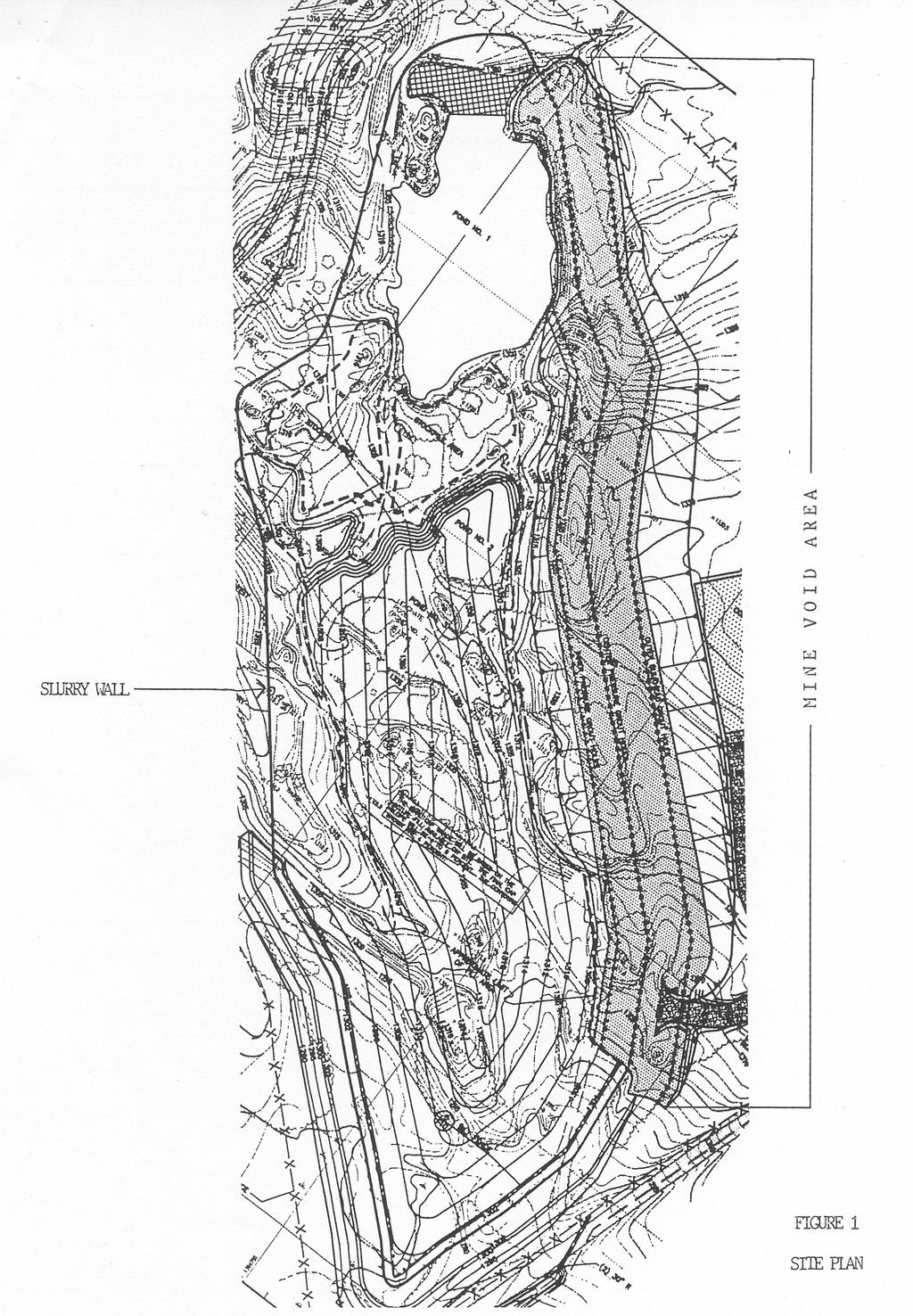
2 #47 CASE STUDY INSTALLATION OF A SOIL-BENTONITE CUTOFF WALL THROUGH AN ABANDONED COAL MINE Michael J Carey 1, Michael J. Fisher 2 and Steven R. Day 3 Abstract The site is a 72,846 square meter (18-acre) abandoned strip mine located in Western Pennsylvania used for municipal and industrial waste disposal until the mid-1970 s. The waste pit is adjacent and connected to a flooded deep mine which saturated the waste over the past 20 years. The site was placed on the National Priority List in 1984, primarily due to the presence of drums on the surface of the site. EPA s proposed remedial action for the site included excavation and stockpiling of the waste materials, backfilling the pit with clean materials, constructing a RCRA cell on the clean materials, and disposing of the waste into the cell. The estimated cost of EPA s remedy was approximately $26 million. An alternative action proposed included in-place closure and containment at the site. Many were unsure whether a slurry cutoff wall could be installed through the deep mine adjacent to the waste pit. The proposed alternative of grouting mine boids to facilitate slurry wall installation had never been performed on a Superfund site, and resulted in a cost savings of approximately $15 million. the grout and slurry wall were successfully installed, with complete closure expected by spring of Introduction The project is a Superfund site in Western Pennsylvania. The site shown in Figure 1 is an abandoned strip mine from the Brookville Coal Seam covering an area approximately 72,846 square meters (18 acres). Adjacent to the northeast side of the strip mine is a deep mine and high wall. The majority of the area 1 Geo-Con, Inc Monroeville Blvd., Suite 400, Monroeville, PA 15146, (412) , mjcarey0@ccmail.wcc.com 2 Geo-Con, Inc., 4075 Monroeville Blvd., Suite 400, Monroeville, PA 15146, (412) , mjfishe0@ccmail.wcc.com 3 Geo-Con, Inc., 4582 S. Ulster Street, Stanford Place, Suite 1000, Denver, CO 80237, (303) , srdayxx0@ccmail.wcc.com
3 immediately surrounding the site is used for agricultural purposes, however, there are several residences 250 meters (829 feet) north of the site. It is estimated that strip mining at the site began in the early 1900 s and concluded in the late 1940 s. A 460 meter (1,500-foot) long pit through the center of the site was a remnant of the strip mining operation. The site was operated as a disposal area from the 1950 s to The majority of the material disposed of was dark, coarse foundry sand along with slag, scrap metal, wood, paper, and plastic matter. Drums were placed on the surface of the site, but were removed during a separate project. The disposal operation was halted by the Pennsylvania Department of Environmental Resources in The presence of drums at the site attracted regulatory interest. Following preliminary sampling, the site was brought to the attention of EPA for inclusion in the Superfund program and added to the National Priority List in Site stratigaphy from surface is as follows: 6 to 15 meters (20 to 46 feet) of overburden full, comprised of mine spoils, landfill materials and fill materials; the Clarion rock formation 6 meters (20 feet) above the abandoned coal mine; the Brookville Coal Seam 1.2 to 2.5 meters (4 to 8 feet) thick; the Brookville Coal Underclay 1 to 2.5 meters (3 to 8 feet) thick; and the Homewood Sandstone formation 10 meters (30 feet) thick. Contaminants found in the waste were benzo(a)pyrene, dibenzo(a,h)anthracene, chromium, lead and nickel. Because fill material was deposited below the water table into the mine pool, EPA concluded that the site groundwater was contaminated with the same materials found in the waste. Additionally, low levels of vinyl chloride and trichloroethene were detected in the onsite groundwater. Disposed materials had contaminated onsite shallow groundwater, Clarion Formation groundwater and the Homewood Formation groundwater. Onsite waste materials were considered a current dermal contact risk, and migration of contaminated groundwater considered a potential future risk. Remedial Actions Objectives of closure were as follows: Prevent migration of contamination through the groundwater; Prevent infiltration of surface water into the contaminated area; Prevent contact with contaminated materials.
4 EPA s preferred alternative for remediation of the site included construction of a RCRA compliance landfill at the site. This alternative would have achieved the desired objectives, but had an estimated cost of the $26 million. The plan included excavating and stockpiling wastes onsite while the RCRA cell was constructed. The cost of this alternative was high because much of the waste was located below the water table, requiring a dewatering system and treatment of the wastewater before discharge. The Alternative Remedial Action proposed by the owner and engineer was onsite closure accomplished by installing a soil-bentonite slurry wall around the perimeter of the contaminated area and installation of a low permeability GCL cap. Extraction wells installed inside the slurry cutoff wall would collect contaminated groundwater and send it to onsite water treatment system. Estimated cost of the alternative remedy was approximately $10 million. The main difficulty at this site was the abandoned deep mine adjacent to the landfill. Landfill closures using soil-bentonite slurry walls and low permeability caps are common. The challenge posed by this closure was the installation of approximately 275 meters (900 linear feet) of slurry wall through the deep mine, because realignment of the slurry wall was not feasible. EPA initially decided the alternative remedy would not be acceptable for this reason, but later agreed to consider the action if a panel comprised of EPA and Army Corps of Engineer experts deemed the installation feasible. The remedial action was approved pending resolution the following: 1. Verification of coal seam underclay presence along the entire alignment of the slurry wall through the deep mine. The underclay acts as the confining or key material for the cutoff wall. 2. Demonstration that the remedial action could control damage to the cutoff wall or cap due to potential mine subsidence. 3. Demonstration that the remedy would not adversely impact the mine pool and could be feasibly constructed at a reasonable cost. Slurry Wall and Grouting The slurry wall technique uses an engineered fluid, water, and bentonite (in this case), to support the sidewalls of deep, vertical trench. The presence of mine voids as high as 2.4 meters (8 feet) made the construction of a slurry wall impossible at this site. Excavating a slurry wall through voids of a deep mine would cause an immediate and catastrophic loss of the slurry. Mine grouting was selected as the technique to fill the voids. Grouting was performed along the slurry wall alignment for two purposes: to provide containment for slurry wall construction, and to prevent damage to the wall and
5 cap due to potential mine subsidence. Three lines of grout holes were installed along and adjacent to the centerline of the slurry wall. An outer bulkhead was installed 15 meters (50 feet) outside the slurry wall. A second row of grout holes was installed approximately 10.5 meters (35 feet) inside the slurry wall alignment and adjacent to the landfill and highwall. The third row of holes was placed directly along the slurry wall alignment. Standard air rotary drilling rigs were used to install the grout holes. 200 millimeter (eight-inch) diameter steel casing was installed through the overburden to the top of the Clarion rock formation. A 100 millimeter (4-inch) diameter hole was drilled through the rock formation. Borings were drilled along all three boring alignments on 3 meter (10-foot) spacings to identify mine voids and highly fractured rock. When voids were encountered, hole spacing was decreased 1.5 meter (5-foot) on centers. The contractor performed a mix design to determine the flyash to cement ratio required to meet the strength specification of 100 psi after 7 days for both low and high slump grouts required for the project. The low slump grout, which was required to have a slump in the range of 25 to 75 millimeters (1 to 3 inches), consisted of 9:1 flyash to cement and a water to solids ratio of The high slump grout, with a required slump in the range of 200 to 250 millimeter (8 to 10 inches), consisted of 8:1 flyash to cement with a water to solids ratio of 1.3. Both grouts were required to have a minimum compressive strength in 7 days of 100 psi. Grouting work began with the outer bulkhead borings. To assure detection of all possible voids, the specification required that each outer hole be drilled 0.6 meters (2 feet) into the Brookville Coal Underclay. A low slump grout, prepared at the onsite plant, was injected through a grout pipe inserted to the bottom of the hole. As the pressure built, the pipe was raised creating a column of grout. As the process is repeated in adjacent holes, a bulkhead is constructed. The purpose of the low slump grout is to create a barrier to contain the high slump pressure grouting performed for the inner and slurry wall grout holes. Once a sufficient number of outer bulkhead holes were completed, work began on the inner and center pressure holes. The inner row of holes were drilled 0.6 meters (2 feet) below the Brookville Coal Underclay and the center pressure was drilled 1.5 meters (5 feet) into the Brookville Coal Underclay. Both sets of holes were pressure grouted with high slump grout, filling voids both in the mine and in the highly fractured rock. Figure 3 is a cross section through the 3 rows of grout holes. The cutoff wall specified for the project was a 0.6 meters (2 foot) wide soilbentonite wall installed by the slurry trench technique. This wall was keyed a minimum of 1 meter (3 foot) into the Brookville Coal Underclay, where present, or 1.5 meters (5 feet) into the underlying Homewood Sandstone which also served
6 as a confining zone. In the deep mine area, the cutoff wall is keyed into the Underclay. The wall backfill was specified to have a hydraulic conductivity of 1x10⁻⁷ cm using a mixture of the excavated soils sand 2% bentonite clay. The bentonite slurry, used to support the trench, forms a cake on the trench sidewalls, plugging the soils and forming a hydraulic barrier. The permanent wall is formed by replacing the slurry with an engineered low permeability backfill. Trench stability is maintained during construction by controlling slurry properties (density, viscosity, etc.) and by keeping the slurry level in the trench above the groundwater table. The Contractor performed mix designs to determine that 2% bentonite would need to be added to site soils to assure the wall backfill would meet the performance specification. To achieve the 2% bentonite addition, 1% dry bentonite was added to the spoils removed from the trench. An industry standard, yet a conservative assumption, is that of 1% bentonite is incorporated into the spoils excavated using the slurry trench method. Slurry for the trench was made by mixing onsite pond water with premium grade sodium/calcium montmorillonite clay, or bentonite. The materials were mixed to a homogeneous, colloidal suspension in a specially designed 12.5 cubic meter (5-cubic yard) colloidal mixer. The slurry was required to have a density of at least 64 pcf and a marsh funnel viscosity of 40 seconds at the plant before introduction to the trench. Typically, 4 to 5 45 kilogram (100-pound) bags of bentonite were added to approximately 3,200 liters (850 gallons) of mix water to ensure trench stability and to meet specifications. Mine grouting for the project was performed in the fall of Mine voids along approximately 275 meters (900 linear feet) of slurry wall were grouted. Approximately 250 linear feet of the wall was installed through unmined coal. The grouting program included installation of 660 borings, 9,850 meters (32,500 linear feet) of drilling. A total of 22,300 cubic meters (9,000 cubic yards) of grout was replaced. The slurry wall was installed through the deep mine area in the spring of Excavation of grout materials did not pose a problem due to the relatively low compressive strength of 100 psi. The wall was completed through the deep mine area without any measurable loss of slurry or backfill cave-ins. Another anticipated problem was the effect of cement on the bentonite slurry. Bentonite slurry walls constructed through cement stabilized soils have historically had problems with flocculation of the bentonite. Lignosulfanate was approved as an additive to bentonite slurry to counteract this effect. No problems were experienced on this project and lignosulfanate was not required.
7 Summary and Conclusions This containment project was started in the summer of 1995, and successful completion is expected in the spring of Applying engineering and construction ingenuity, project remediation costs were reduced approximately 60% by allowing inplace containment versus excavation and removal to an offsite RCRA hazardous waste landfill. This project illustrated that cutoff walls can be installed through areas with large voids, such as deep mines. The grouting program was successful in sealing the voids and containing the slurry during construction. The project illustrates the potential for use of grouting and slurry wall installation in combination to provide a cutoff barrier through other types of subsurface voids and fractures. References Woodcock, J., Weinzierl, R. and Miller, K. (1996) CERCLA Landfill Closure Utilizing Slurry Wall Construction in Deep Mined Area.
8
9