TITLE MetroLink. the St. Louis region s light-rail system CHARLES F. CLEMINS, JR. SENIOR DIRECTOR, MAINTENANCE OF WAY METRO TRANSIT
|
|
|
- Corey Bell
- 5 years ago
- Views:
Transcription


1 TITLE MetroLink the St. Louis region s light-rail system CHARLES F. CLEMINS, JR. SENIOR DIRECTOR, MAINTENANCE OF WAY METRO TRANSIT


2 Bi-State Development Established in 1949 through an interstate compact between Missouri & Illinois Able to operate across state boundaries Focus on regional development and economic growth


3 Metro Transit Metro Transit in St. Louis operates in a 600 square-mile service area in Missouri and Illinois Service options include: 400-vehicle MetroBus fleet 46-mile MetroLink light rail system 120-vehicle Metro Call-A-Ride paratransit service More than 40 million boardings last year Industry leader in operations, on-time performance and maintenance

4 Opened July miles and 37 stations Two major expansions 38 th station set to open in 2018 MetroLink

5 MetroLink Facts Alignment is all double track, except for a single track section at the airport Two rail yards, each with about one mile of track 112 mainline and yard switches 25 grade crossings


6 MetroLink Facts 24 interlockings 860 VDS overhead catenary system Automatic train protection system (cab signal system)
7 MetroLink Track Facts In Service Mile Post CC CC 7.7 Miles Crosstie Wood Concrete Concrete Concrete Tie Quantity 84,000 73,000 15,000 32,000 Fastening Cut spikes + tie plates Resilient, fast clip type Resilient, fast clip type Resilient, fast clip type Rail 132RE, used 115RE, new 115RE, new 115RE, new Ballast Slag Granite trap rock Granite trap rock Granite trap rock

8 MetroLink Track Inspections WeeklyHi-rail visual of the alignment Monthly Trimonthly Walking visual of switches Ride quality
 Track geometry testing of concrete tie")
9 MetroLink Track Inspections Semiannual Ultrasonic rail testing Annual Triennial Track geometry testing of wood tie section Turn out (thorough) Track geometry testing of concrete tie sections

10 MetroLink Track Projects Since 2008 Curve worn rail replacement Seven grade crossing replacements Three interlockings added, one w/pocket track 36,000 wood ties replaced Track replace on historic Eads Bridge Rail surface grinding One station to be added (Summer 2018)

11 MetroLink Track Future Projects Two more grade crossing replacements Restraining rail curve replacement Replace rail and fasteners on a 1930s steel deck bridge Replace track at several elevated areas

12
13 TITLE MetroLink the St. Louis region s light-rail system CHARLES F. CLEMINS, JR. SENIOR DIRECTOR, MAINTENANCE OF WAY METRO TRANSIT


14 Resilient Concrete Crosstie and Fastening System Design for Rail Transit Systems Project Summary, Select Findings, and Crosstie Prototyping Marcus Dersch, Riley Edwards, Minsoo Sung, and Bassem Andrawes May 15, 2018

15 Acknowledgements Research Sponsor Education Program Sponsor Industry Partners RailTEC at Illinois 2
16 FTA-Funded Resilient Concrete Crossties and Fastening System Research Program Objectives Develop resilient concrete crosstie design solutions for light, heavy, and commuter rail transit operators Methodology Quantify concrete crosstie and fastening system demands when subjected to rail transit loading environments Key Parameters to Quantify Loading Environment (lateral and vertical wheel/rail loads) Crosstie Bending Moments (rail seat and center) Rail Displacements (vertical and lateral) RailTEC at Illinois 3
17 FTA Project Approach Paper Study Industry Surveys Field Data Collection Resilient Concrete Crosstie and Fastening System for Rail Transit Laboratory Testing Analytical Modelling Other Factors RailTEC at Illinois 4

 RailTEC at")
18 FTA Project Transit Partner Agencies (Two Sites; Curve & Tangent) RailTEC at Illinois 5
19 FTA Project Field Instrumentation Map Metrics to quantify: Vertical and lateral input loads (crosstie and fastening system design, and load environment characterization) Crosstie bending strain (crosstie moment design) Rail displacements (fastening system design) Crosstie temperature gradient Crosstie Bending Strain Vertical and Lateral Load (Wheel Loads) Rail Displacement (Base Vertical, Base Lateral) Rail Displacement (Base Vertical) Thermocouple Laser Trigger RailTEC at Illinois 6

20 Installation of St. Louis MetroLink Field Site RailTEC at Illinois 7

21 RailTEC at Illinois 8
22 Vertical Rail Loads St. Louis MetroLink (Tangent) AW0 = Empty Weight AW3 = Crush Load RailTEC at Illinois 9
23 Vertical Rail Loads St. Louis MetroLink (Tangent) AW0 = Empty Weight AW3 = Crush Load RailTEC at Illinois 10
24 Modal Comparison: Vertical Rail Loads Commuter Rail Heavy Rail Light Rail Commuter Locomotive <0.05% wheel impacts exceed impact factor of 3 RailTEC at Illinois 11
 These values are")


25 Load Data in AREMA Chapter 30 (2018) These values are intended to represent the North American loading regime and are not intended to be used for design RailTEC at Illinois 12
 Rail displacements (fastening system design) Crosstie temperature gradient Crosstie Bending Strain Vertical and Lateral Load (Wheel Loads) Rail Displacement (Base Vertical,")
26 FTA Project Field Instrumentation Map Metrics to quantify: Vertical and lateral input loads (crosstie and fastening system design, and load environment characterization) Crosstie bending strain (crosstie moment design) Rail displacements (fastening system design) Crosstie temperature gradient Crosstie Bending Strain Vertical and Lateral Load (Wheel Loads) Rail Displacement (Base Vertical, Base Lateral) Rail Displacement (Base Vertical) Thermocouple Laser Trigger RailTEC at Illinois 13
27 Center Negative (C-) Bending Factor of safety is approximately: 6 for the maximum MetroLink C- bending moment measured 2 for the maximum NYCTA C- bending moment measured RailTEC at Illinois 14
28 Rail Seat Positive (RS+) Bending Factor of safety is greater than: 3 for the maximum MetroLink RS+ bending moment measured 4 for the maximum NYCTA RS+ bending moment measured RailTEC at Illinois 15
29 Field Experimentation Takeaways Loading environment is significantly different at each transit mode Design of any infrastructure component should consider this Wheel loads exceeded an impact factor (IF) of 3 rarely (<0.05%) AREMA recommends designing concrete crossties with an IF of 3 The reserve flexural capacity factors of safety ranged from 2 6 This provides an opportunity to optimize not just the crosstie design but track structure Savings from reductions in concrete, steel, & handling could be reallocated into resilient materials (under tie pads, ballast mats, etc.) Resilient materials could: Reduce maintenance costs (e.g. increase time between tamping, etc.) Reduce urban pollution (i.e. ground borne noise and vibration, etc.) RailTEC at Illinois 16
30 FTA Project Approach Paper Study Industry Surveys Field Data Collection Resilient Concrete Crosstie and Fastening System for Rail Transit Laboratory Testing Analytical Modelling Other Factors RailTEC at Illinois 17

31 Concrete Crosstie Design Considerations Rail Seat Flexure Rail Seat Robustness Center Flexure Allowable Ballast Pressure RailTEC at Illinois 18
32 Initial Prototype Experimentation Concurrent with Field Data Collection Purpose: Identify how failure modes change varying key parameters Determine a method to ensure a safe ultimate failure Develop, calibrate, and validate a finite element model Various Trials Prestressing quantity and arrangement Assist model calibration Synthetic Fibers in Concrete Quantify failure mode/benefits of fibers Shear and flexural reinforcement Quantify effect of stirrups on failure mode (shear/flexural) RailTEC at Illinois 19


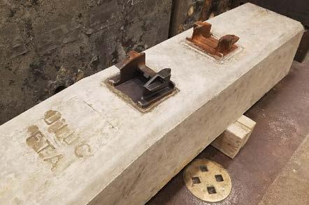
33 Prototype Crosstie Manufacturing RailTEC at Illinois 20
 Fiber")

34 Qualitative Prototype Results Standard Crosstie: Failure representative of typical crossties (i.e. shear) Fiber Prototype: Failure with more cracks, reduced crack width and non-shear Stirrup Prototype: Failure typical RailTEC at Illinois 21

35 Final Prototype Development Design Optimization Framework RS+ and C- set from field data Establish Target Safety Factors Preliminary Analysis Calculate cracking moment through section analysis varying: Section depth, Number of wires Eccentricity Run C- and RS+ Simulations Quantify cracking and ultimate moments Finite Element Analysis RailTEC at Illinois 22
 surface for RS+ & C- 2.")

36 Preliminary Analysis: Work Flow 1. Develop safety factor ( ) surface for RS+ & C- 2. Combine Surfaces & Include Safety Factor planes 3. Plot intersections Intersection will be depth and centroid First Crack Moment Calculations: ACI RS+: 178 kip-in. C-: 56.3 kip-in. UIUC FEM RS+: 197 kip-in C-: 89.8 kip-in. RailTEC at Illinois 23


37 Path Forward: Installation and Monitoring at MetroLink & Project Dissemination Install Prototypes Late Summer/Early Fall Monitor Performance Through Spring 2019 Project Dissemination Loading Environment Bending Demands Fastener Displacement Design Framework RailTEC at Illinois 24
38 Acknowledgements Research Sponsor Education Program Sponsor Industry Partners RailTEC at Illinois 25
 Rail Transportation and Engineering Center (RailTEC) This project is funded by the Department of Transportation s Federal Transit Administration")
39 Thank you for your attention! Marcus Dersch Senior Research Engineer University of Illinois at Urbana-Champaign (UIUC) Rail Transportation and Engineering Center (RailTEC) This project is funded by the Department of Transportation s Federal Transit Administration and supported by the National University Rail Center (NURail), a US DOT-OST Tier 1 University Transportation Center RailTEC at Illinois 26