MCCOOK MTS BIFURCATION A PARADIGM OF CRAFTSMANSHIP CLAY HAYNES NASH WILLIAMS
|
|
|
- Dominic James
- 5 years ago
- Views:
Transcription

1 24 June 2014 MCCOOK MTS BIFURCATION A PARADIGM OF CRAFTSMANSHIP CLAY HAYNES NASH WILLIAMS ENGINEERING MANAGER WATER SECTOR PRESIDENT NATIONAL WELDING CORPORATION


2 HISTORY OF THE CHICAGOLAND UNDERFLOW PLAN 2
 in the largest water infrastructure undertaking in Chicago ($3.5 billion) 3")
3 THE CHICAGOLAND UNDERFLOW PLAN TARP - TUNNEL AND RESERVOIR PLAN MCCOOK MTS BIFURCAQTION Following the reversal of the Chicago River in the early 1900s, the Chicagoland area continued to develop & pollution of local waterways continued In 1972, MWRDGC adopted the Tunnel and Reservoir Plan (TARP) in the largest water infrastructure undertaking in Chicago ($3.5 billion) 3
 Des Plaines Calumet Phase II - Three large reservoirs: McCook (under construction) O Hare")
4 TARP SYSTEM MAP Upper Des Plaines (O Hare) 4 MCCOOK MTS BIFURCAITON Phase I miles of tunnel Mainstream Upper Des Plaines (O Hare) Des Plaines Calumet Phase II - Three large reservoirs: McCook (under construction) O Hare (complete) Thornton Composite (under construction) Des Plaines Mainstream Calumet
5 MCCOOK RESERVOIR OVERVIEW 5

6 MCCOOK RESERVOIR Authorized in Water Resources Development act of 1999 Will provide 10 BG of CSO and flood storage for TARP Mainstream and Des Plaines Deep Tunnel System Stored volume will be pumped to Stickney WWTP for treatment before discharge into Des Plaines River MCCOOK MTS BIFURCAITON 6


7 MCCOOK RESERVOIR FACILITIES LAYOUT Mainstream Pumping Station and McCook Distribution Tunnel System (complete) MCCOOK MTS BIFURCATION McCook Main Tunnel Connection System
8 MCCOOK MAIN TUNNEL SYSTEM 8

9 MCCOOK MAIN TUNNEL SYSTEM KEY PROJECT ELEMENTS Drill and Blast Tunnel connecting Mainstream Tunnel to McCook Reservoir 1,600 ft long 33 ft diameter Bifurcated for 290 ft through Main Gate/Access Shaft Sump / Reservoir Region Bifurcation & Transition Region TARP / Mainstream Tunnel Connection Region MCCOOK MTS BIFURCAITON McCook Reservoir Portal / Energy Dissipation Gates Gate / Construction Access Shaft To Stickney WRP Rock Bulkhead From Mainstream TARP TARP Connection 9


10 MCCOOK MAIN TUNNEL SYSTEM KEY PROJECT ELEMENTS Mainstream Tunnel Connection Live connection Geometry analyzed with CFD to determine best geometry 45 degree elliptical mitre Note separation of flow at connection MCCOOK MTS BIFURCATION Maximum velocity = 48ft/s Minimum absolute pressure = 0.6atm Region with sub-atmospheric pressure 10
11 HYDRAULIC ANALYSIS
12 HYDRAULIC ANALYSIS PURPOSE McCook Reservoir Sump Gates To Stickney MCCOOK MTS BIFURCATION Layout of tunnel system as generally modeled McCook Tunnel (33ft dia.) Mainstream Tunnel (33ft dia.) 12

13 MCCOOK MTS BIFURCATION HYDRAULIC ANALYSIS MAIN CONCERNS Cavitation The formation of vapor bubbles in low pressure areas Vapor bubbles are carried downstream and in an area of higher pressure, will condense and collapse suddenly Abrasion Damage to tunnel lining caused by significant quantities of sand, gravel, rock, and other debris found in storm water, in high velocity flows CFD Model of Energy Dissipation Structure in Reservoir 13
14 MCCOOK MTS BIFURCAITON HYDRAULIC ANALYSIS MODELING APPROACH Computational Fluid Dynamics (CFD) ANSYS CFX Code Set up a mesh which splits water into a large number of small elements Predicts flow by solving iteratively a series of equations for conservation of mass momentum and energy Peak flow During storm events, most of the flow in the Mainstream Tunnel will be routed through the Main Tunnel. Flows in the Mainstream Tunnel average 30 ft/s Assumes gates are in open position 14
15 MAIN GATE SHAFT 15


16 Skin Plate Intercostals/Diaphragm Plates Wheel Axle Girders Flange Plates 3D CAD Drawing of Gate MCCOOK MTS BIFURCATION Gate ANSYS Model 6 gates operated by hydraulic cylinders in guide slot by wheels Gate Fabrication 16


17 MAIN GATE SHAFT GATE HYDRAULICS MCCOOK MTS BIFURCATION All gates designed to resist static load ft of hydraulic head 6 main gates Resist flow in both directions ft wide, approximately 30 ft tall Over 200,000 lbs each 17

18 STEEL LINER CONSTRUCTION 18
19 THE RIGHT TEAM National Welding Corporation Assemble, Fit, and Weld Steel Tunnel Liner A PARADIGM OF CRAFTSMANSHIP Kiewit Infrastructure- General Contractor, Excavate, Concrete Lining, and oversight. Selway Corporation- Shop Drawings and Fabrication of Steel Liner Pieces. SELWAY 19
 of steel liner Bifurcation from 10 m (33")
 Designed for 6 High Wheel Gates for flow")
20 PREASSEMBLY PLANNING A PARADIGM OF CRAFTSMANSHIP Design 108 m (354 ft) of steel liner Bifurcation from 10 m (33 ft) to 4x9.8 m (19x32 ft) Designed for 6 High Wheel Gates for flow control Changing Geometry T Steel rings 20


21 FABRICATION OF STEEL LINER SECTIONS Tolerances Connections Preassembly A PARADIGM OF CRAFTSMANSHIP Shipping Considerations MT to IL using 48 special loads 21


22 SURFACE SUBASSEMBLY A PARADIGM OF CRAFTSMANSHIP 10 m (33 ft) Diameter Pieces Assembled Onsite 22


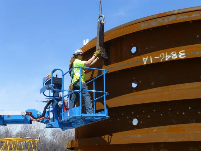
23 RIGGING AND CONNECTIONS A PARADIGM OF CRAFTSMANSHIP Bolted Connections Custom Rigging for each ring of liner 23


24 A PARADIGM OF CRAFTSMANSHIP LINER SUPPORT Cross-Bracing Installation 24


25 ENVIRONMENTAL CONTROLS Surviving Chicago s Winter A PARADIGM OF CRAFTSMANSHIP Temporary Shelter 25


26 FINAL FIT-UP AND WELD-OUT Seam Fitting Roundness Tolerance A PARADIGM OF CRAFTSMANSHIP FCAW Welding 26


27 QUALITY CONTROL Magnetic Particle (MT) inspection A PARADIGM OF CRAFTSMANSHIP Ultrasonic Testing (UT) Inspection 27


28 A PARADIGM OF CRAFTSMANSHIP J ANCHOR LAYOUT AND WELDING Over 16,000 Anchors-Field Installed 28


29 CHANGING GEOMETRY Bifurcation A PARADIGM OF CRAFTSMANSHIP Bull Nose 29


30 A PARADIGM OF CRAFTSMANSHIP HANDLING 33 FOOT DIAMETER SECTIONS Rotation of 164mt (180 tons) 30


31 A PARADIGM OF CRAFTSMANSHIP 8 March 2012 HANDLING 33 FOOT DIAMETER SECTIONS Sections Lowered Down 91 m (300 ft) Shaft 31


32 TUNNEL INSTALLATION A PARADIGM OF CRAFTSMANSHIP Sections transported into position Annular Bracing Installed 32

")


33 CIRCUMFERENTIAL SEAMS FITTING AND WELDING Over 937 m (3076 ft) of CJP tunnel welds performed A PARADIGM OF CRAFTSMANSHIP Automatic and Semi- Automatic FCAW Welding 33

34 FINISHED STEEL TUNNEL LINER KEY ELEMENTS OF SUCCESS A PARADIGM OF CRAFTSMANSHIP 1. Team Approach 2. Capable Team Members 3. Careful Planning and Development 34

35 A PARADIGM OF CRAFTSMANSHIP 8 March 2012 nash@national-welding.com HaynesCE@bv.com 35