1000 CONTINENTAL SQUARE
|
|
|
- Rudolph Houston
- 5 years ago
- Views:
Transcription
1 1000 CONTINENTAL SQUARE KING OF PRUSSIA, PENNSYLVANIA Carter Davis Hayes Structural Option January 13, 2008 Advisor: Dr. Hanagan
2 TABLE OF CONTENTS TABLE OF CONTENTS... 2 EXECUTIVE SUMMARY... 3 I. STRUCTURAL SYSTEMS... 4 Foundations... 4 Floor Framing... 4 Columns... 5 Lateral Load Resisting Systems... 5 II. CODES AND MATERIALS... 6 Codes... 6 Materials... 7 III. DESIGN LOADS... 8 Live Loads... 8 Dead Loads... 8 Wind loads... 8 Seismic Loads IV. LATERAL SYSTEM ANALYSIS Lateral Analysis RAM Model Drift Story Drift Overturning Moment Torsion V. CONCLUSIONS VI. APPENDICES A.1 Spot Checks A.2 Drifts A.3 Centers A.4 Deflections Under Unit Loading Page 2

3 EXECUTIVE SUMMARY This is the third of three preliminary stages of analysis intended to impart a better understanding in each student of their individual building, and acts as an attempt to better focus research for the final thesis in the spring. This third paper focuses on the lateral force resisting systems and how lateral loads are distributed to different elements in those systems. My project is based on the design of the office building currently under construction at 1000 Continental Square in King of Prussia, PA. The building is high end office space featuring large open floor plans with uninterrupted forty foot bays along each side of the building. The site has a prominent location at the intersection of routes 202, 76, and 422, and is in close proximity to the PA Turnpike and King of Prussia Mall. A ground floor, partially below grade, serves mainly as space for mechanical systems and storage. Five floors of approximately 36,000 square feet of leasable space are located above that. The building makes use of a steel structural frame with composite metal decking and lightweight concrete slabs. Lateral loads are resisted by two moment frames along the long axis of the building and two eccentrically braced frames along the short axis. Page 3


4 I. STRUCTURAL SYSTEMS FOUNDATIONS The foundations for 1000 Continental Square are a series of spread footings with continuous wall footings under the retaining walls located on the ground floor. The soils under the footings were found to withstand 4000 psf in most locations according to the geotechnical report furnished by Pennoni Associates Inc. on 24 of February Suitable bearing pressures were attained by deep dynamic compaction or partial soil exchange. Footing dimensions range from 4 x 4 x 1.5 to 20 x 20 x 4 ; however, typical footings are approximately 14 x 14 x 3. Special 55 x 18 x 3.5 spread footings are used under the braced frames. The tops of most footings are located 1.5 below grade, and minimum bearing depth is 3. Columns either bear directly on footings or in some atypical situations concrete piers are placed on top of the footings and columns bear on those. Footings have bottom reinforcement ranging from (7) #4 s to (16) #11 s with typical reinforcement being approximately (12) #9 s. The continuous wall footings are integrated into the spread footings they intersect, and their reinforcement is continuous throughout. Concrete in all footings has a minimum compressive strength, f c = 3000 psi with a unit weight of 145 pcf. There is a 4 thick slab on grade which acts as the floor system for the ground floor and utilizes 4000 psi compressive strength concrete. FLOOR FRAMING All the floor framing above grade in the 1000 Continental Square project is 6¼ composite slabs. They consist of 3¼ lightweight concrete over 3 deep 20 gage galvanized composite floor deck. The slab is reinforced by one layer of 6 x 6 W1.4 x W1.4 WWR, and has a weight of 115 pcf and a compressive strength of 3500 psi. This is supported by W 18 x 35 s spanning 40 bays which tie into an assortment of girders spanning 30 ; W 24 x 55 s being the most typical. Composite action Page 4

5 is achieved through 6 long ¾ diameter headed studs, approximately 34 evenly spaced per beam. The W 18 s feature a typical camber of 1.5. Variations in design occur at architectural features, the elevator shafts, and intersections with the moment frames, elsewhere the system is nearly identical on all floors. COLUMNS The column grid for the building is laid out rectilinearly using three spans: 40, 35, 40, in the N-S direction and (10) 30 spans in the E-W, thereby creating large, uninterrupted, regular bays to simplify leasing. Column sizes vary between W 12 X 230 s on the first floor of the moment frames to W 12 X 40 s for gravity columns on the top floors. Splice levels are located a maximum of 4ft above the second and fourth floors. Typical columns are W 12 x 152 s on the bottom floors, W 12 x 96 s on the middle floors, and W 12 x 40 on the top levels. Typical columns are fixed to foundations with four ¾ diameter anchor rods with 1 embed depths and 4 hooks. LATERAL LOAD RESISTING SYSTEMS 1000 Continental Square is reinforced against lateral loads by different systems along its long axis (E-W) and short axis (N-S). In the E-W direction two moment frames fit into the existing grid along column lines B and D, and act over the full height of the building and effectively its full length. In the N-S direction two full height eccentrically braced frames fit off grid between lines B and C along column lines 3 and 9 to provide support for the short axis. These systems act to counter both wind and seismic forces, however wind loads were found to control the design in this situation. There are two additional types of one story braced frames used in the building to mainly support architectural elements which are not analyzed in this report. Page 5
6 II. CODES AND MATERIALS CODES Building Code: 2004 Pennsylvania Uniform Construction Code Building Subcode: International Building Code (IBC) 2003 Minimum Design Loads: American Society of Civil Engineers (ASCE), 7-02 Reinforced Concrete: American Concrete Institute (ACI), Precast Concrete: Steel Construction: Steel Decking: Concrete Reinforcing Steel Institute, Manual of Standard Practice, 27 th Edition, March 2001 Precast/Prestressed Concrete Institute (PCI), Design Handbook 5 th Edition American Institute of Steel Construction (AISC), Manual of Steel Construction, LRFD, 3 rd Edition, 2001 Steel Deck Institute, Design Manual Page 6
7 MATERIALS Cast in place concrete (normal weight 145 pcf) Footings 3,000 psi Topping slabs 3,000 psi Lightweight slabs on metal deck (115 pcf) 3,500 psi Normal weight slabs on metal deck 3,500 psi Slabs on grade 4,000 psi Walls and piers 4,000 psi Cast in Place on precast 5,000 psi Pourable fill 1,000 psi Precast Concrete (normal weight 145 pcf) Structural precast 5,000 psi Reinforcing Steel All types U.N.O. ASTM A615 60,000 psi Structural Steel W Shapes ASTM A992 50,000 psi Channels, angles, and plates ASTM A36 36,000 psi Round pipes ASTM A53 E or S 35,000 psi Square and Rectangular HSS s ASTM A500 46,000psi Page 7
8 III. DESIGN LOADS LIVE LOADS All floors 100 psf Due to the open floor plan, all areas are assumed to be lobby or corridor space Roof 20 psf Standard flat roof loading Snow load 21 psf From ASCE 7-05 (see below) p f = 0.7C e C t Ip g Equation 7-1 Terrain Category B Section Exposure Partially Table 7-2 Footnote C e 1.0 Table 7-2 C t 1.0 Table 7-3 I 1.0 Table 7-4 p g 30psf Figure 7-1 DEAD LOADS Floor self weight 50 psf From steel deck manufacturer s design tables Roof self weight 5 psf From steel deck manufacturer s design tables Arch. Precast Panels 50 psf Material property Superimposed DL 30 psf (see below) MEP Ceiling Finishes Floor Finishes 20 psf 5 psf 5 psf WIND LOADS Basic Wind Speed 90 mph Exposure Category B Enclosure Category Enclosed Wind Directionality Factor (Kd) 0.85 Importance Factor (I) 1.0 Topographic Factor (Kzt) 1.0 Gust Effect Factor (G) (E-W) or (N-S) Internal Pressure Coefficient 0.18 Page 8
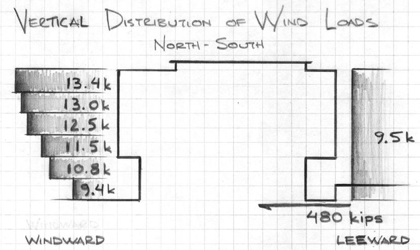
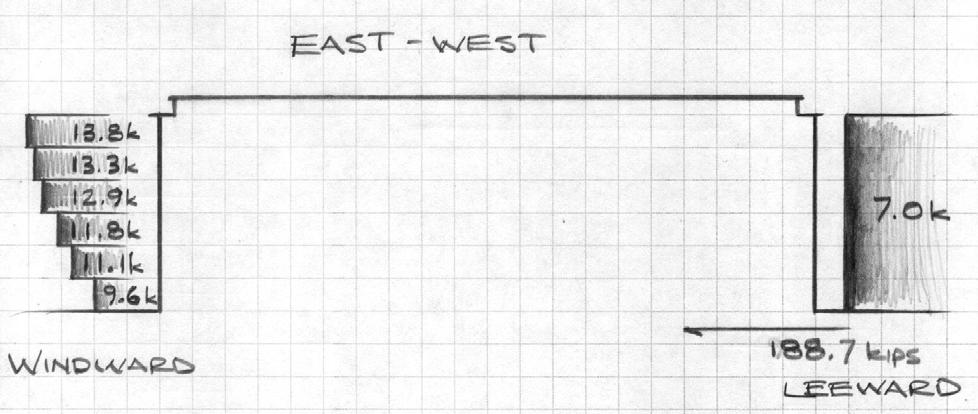
9 VERTICAL DISTRIBUTION OF WIND LOADS Height (ft) Windward Pressure (psf) E-W DIRECTION Leeward Pressure (psf) Total (psf) N-S DIRECTION Height (ft) Windward Leeward Pressure (psf) Pressure (psf) Total (psf) WIND LOAD SUMMARY East - West Direction Base Shear: kips Overturning Moment: 7, kip-ft North - South Direction Base Shear: kips Overturning Moment: 8, kip-ft Page 9
10 Page 10
11 SEISMIC LOADS Item Design Value Code Basis E-W N-S (ASCE 7-05) Hazard Exposure Group I Table 1-1 Performance Catagory B Table ,2 Importance Factor (I) 1.00 Table Spectral Acceleration for Short Periods (S S ) Figure 22-1 Spectral Acceleration for One Second Periods (S 1 ) 0.06 Figure 22-2 Damped Design Spec. Resp. Acc. at Short Periods (S DS ) Section Damped Design Spec. Resp. Acc. at One Second Periods (S D1 ) Section Seismic Response Coefficient (C S ) Section Soil Site Class C Section Basic Structural System Comp. Steel Seismic Resisting System OSMF CEBF Response Modification Factor (R) Table Deflection Modification Factor (C d ) 3 4 Table Analysis Procedure Utilized Equiv. Lat. Force Design Base Shear 420 kips VERTICAL DISTRIBUTION OF SEISMIC FORCES Height (ft) E-W DIRECTION Story Shear (kips) N-S DIRECTION SEISMIC LOAD SUMMARY Base Shear: kips Overturning Moment: 42, kip-ft Page 11
12 Page 12

13 IV. LATERAL SYSTEM ANALYSIS AND DESIGN LOAD ANALYSIS Through the load calculations above it can be determined that wind controls the lateral design along the short axis of the building and seismic controls along the long axis. Tributary area and the loadings above were used to determine lateral forces and the resulting story shears. The controlling wind forces were then applied in the north- south direction which is supported by the two braced frames. Seismic forces were applied in the east-west direction which is supported by the two moment frames. Since the braced frames are identical thy both carry half the applied loads; however, loads on the moment frames were distributed based upon relative stiffness of the two individual frames. The analysis of gravity loads was complete for the largest typical bay, 30 x 40, as that is assumed to be the worst case scenario. Distributed loads were then applied to the supporting beams which run in the long direction and are supported at each end by girders, according to tributary area. The beams were assumed simply supported, then solved for their end reactions which were applied to the girders as point loads, and then subsequently to the columns by the same method. RAM MODEL The lateral system analysis was aided by a RAM Structural System model. For simplicity only the lateral resisting elements and floor diaphragms were modeled. The steel members were modeled as they appear on structural drawings, and the floor system was added as a 3 LOK Flooring with 3.25 of lightweight cover and 5, ¾ diameter shear studs. Additional columns and beams were added in order to create the slab edges however these were not assigned sizes so they do not affect the lateral analysis. DRIFT The analysis of total building drift was completed through the use of the RAM software. I placed the controlling load cases both seismic and wind into the software in their respective directions. Then analyzed drift at each corner of the building as well as the approximate center in order to achieve both the extreme values as well as an average. The computed values for drift were then compared to the code standard for serviceability Δ = H/400 which comes out to 2.34 when computed for 1000 Continental Square. The recorded values, at roof level, at all five points and in both load cases were well under this standard. Page 13
14 STORY DRIFT Individual story shears were checked in respect to seismic loading. Using the same five control points, the seismic drifts at each level were compared to the allowable story drift, Δ = h sx, as given in table in ASCE All story drifts fell below their respective limit values. The exact values can be seen in appendix A.2. OVERTURNING MOMENT Overturning moments were calculated by multiplying each seismic story force and wind load (after it had been distributed to its respective floor diaphragm through tributary area) by the height of that diaphragm. The resulting values for wind were 9439 ft-k (E-W) and ft-k (N- S), and ft-k for seismic. When compared to the moment created by the calculated seismic weight times the minimum moment arm from the center of mass to the most extreme member of that direction s respective lateral system, it is found that all values are within an acceptable range. The moment countering overturning is approximately ft-k in the north-south direction and over 2 million ft-k in the east-west direction. Obviously these moments would not actually be applied around a single point like they are assumed here but distributed throughout the structure; however, these calculations prove the weight of the building is enough to counter the overturning moment resulting from wind and seismic. TORSION Torsion in a building is a result of the eccentricity between the point where lateral loads are applied and the center of rigidity. This is to say the eccentricity between the center of mass and center of rigidity results in torsion from seismic loads, and similarly the eccentricity between the geometric center and center of rigidity results in torsion from wind. It can be assumed torsion has very little effect on the structure in the north-south direction because the centers of mass, rigidity, and geometry are within a foot of each other on every floor except the first and second. However, in the y direction greater eccentricities occur and thus the effect of torsional shears must be checked. This effect can be seen in the deflected shape of the lateral systems at roof level under seismic loads as shown below. Page 14
15 The torsional shear calculations had to be preceded by the calculation of relative stiffness for each lateral resisting frame. This was accomplished using the RAM model by applying unit loads to each frame at each level of the structure and checking their respective deformations. Diaphragms were turned off to prevent interactions between different frames, and all stories below the one being checked were set as below ground to prevent their lateral deflection. The stiffness of each frame was determined by dividing the load by its deformation. Then these were summed for each level so the relative stiffness of each frame on each level to all the others could be determined. The results were that the brace frames generally are much stiffer than the moment frames. As expected since the bother braced frames are identical they are equally stiff and split the loads evenly between then. The moment frames on the other had are not identical but still relatively even except for the first floor where the northern moment frame is partially underground and thus takes 83 percent of the lateral loads for that floor. RELATIVE STIFFNESS Floor N-S E-W BF 1 BF 2 MF 3 MF % 50.0 % 83.2 % 16.8 % % 50.0 % 51.5 % 48.5 % % 50.0 % 47.3 % 52.7 % % 50.0 % 49.2 % 50.8 % % 50.0 % 48.3 % 51.7 % Roof 50.0 % 50.0 % 49.9 % 50.1 % Once the relative stiffness of each frame is computed, torsional effects can be determined. As was stated earlier, due to its symmetry, the north-south direction is ignored. The formula for torsional shear in a direction is /. Here V is the base shear in that direction, R i is the relative stiffness of a frame, and C is the perpendicular distance to the centers of geometry or rigidity depending on whether the load is wind or seismic. Page 15
16 TORSION FROM WIND MF3 MF4 Floor V COG, Y e R i C RC 2 F i R i C RC 2 F i % % % % % % % % % % Roof % % TORSION FROM SEISMIC MF3 MF4 Floor V COR, Y e R i C RC 2 F i R i C RC 2 F i % % % % % % % % % % Roof % % These results show relatively small shear effects from torsion. Wind effects are totally negligible, and in most cases seismic effects were less than 10% of the direct shear. However, the seismic effects should still be added to the direct shears in order to attain the total design shears. These are given in the table below. DESIGN SHEAR IN EAST -WEST DIRECTION Floor Direct Shear Total MF3 Total MF Roof Page 16
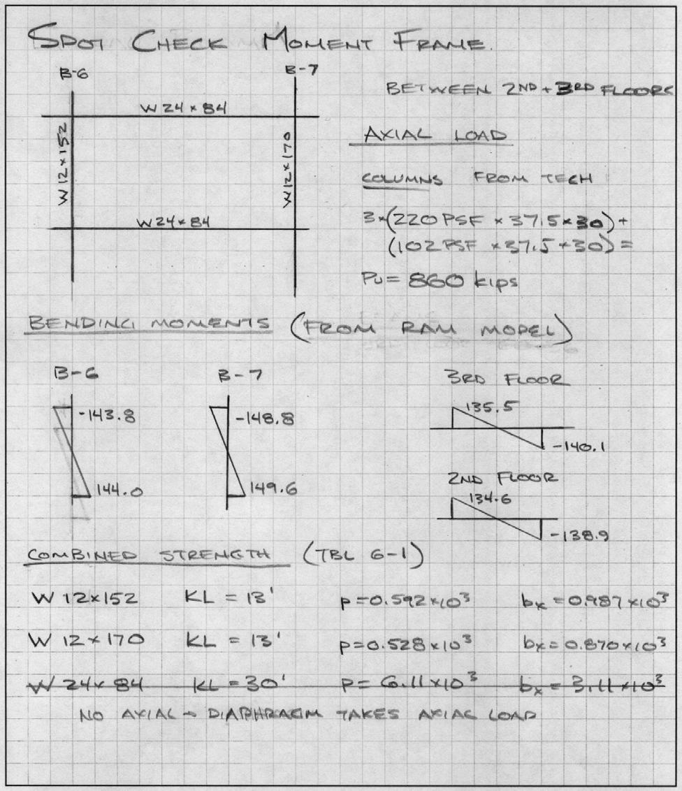
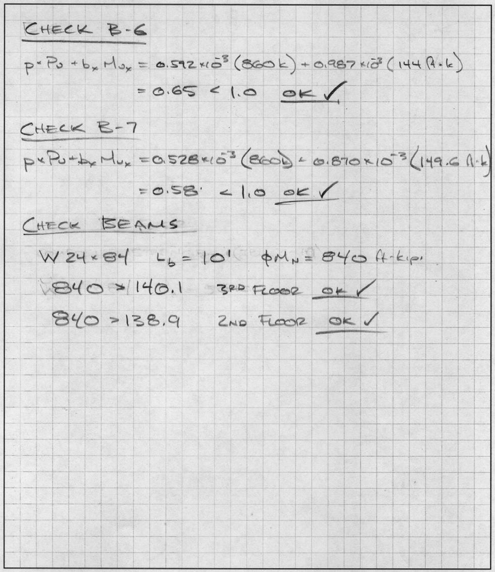
17 V. CONCLUSIONS Through the analysis presented in this report the lateral force resisting system of 1000 Continental Square was investigated through a combination of hand calculations and computer modeling. The computer results were verified by comparison with common sense approximations and spot checks on typical members. The analysis was used to check both strength and serviceability, and results seem to conclude the building is well within code limits. The values found for drift, both overall and within each story, are acceptable by the standards set out in ASCE Both overturning moments and torsional values are easily within the capacities of the structure; although, the effects of torsional shear had to be taken into consideration in the total shear in the east west direction. Spot checks of member sizes seem to imply most members in the lateral system were sized to control deflection since their strength capacities are much higher than necessary. These oversized members could possibly be redesigned, perhaps with one of the alternate flooring systems from technical report two in order to create a more efficient use of material. This idea will be explored in my final thesis in the spring. Page 17
18 VII. APPENDICES Page Left Intentionally Blank Page 18

19 A.1 SPOT CHECKS Page 19
20 Page 20
21 Page 21
22 A.2 DRIFTS Page 22
23 Page 23
24 Page 24
25 Page 25
26 A.3 CENTERS CENTER OF MASS Floor X Value Y Value Height Roof Total CENTER OF RIGIDITY Floor X Value Y Value Height Roof Total CENTER OF GEOMETRY Floor X Value Y Value Height Roof Total Page 26
27 A.4 DEFECTIONS UNDER UNIT LOADING DEFLECTION Floor BF 1 BF 2 MF 3 MF Roof Page 27