MULTIBLADE SMOKE CONTROL DAMPER BRK-J/EI90
|
|
|
- Susanna Webb
- 5 years ago
- Views:
Transcription


1
2 MULTIBLADE SMOKE CONTROL DAMPER BRK-J/EI90 Table of contents MULTIBLADE SMOKE CONTROL DAMPER BRK-J/EI MULTIBLADE SMOKE CONTROL DAMPER BRK-J/EI MULTIBLADE SMOKE CONTROL DAMPER BRK-J/EI90 DIMENSIONS... 6 MULTIBLADE MULTIBLADE SMOKE CONTROL DAMPER BRK-J/EI90 DESIGN / INSTALLATION... 7 MULTIBLADE SMOKE CONTROL DAMPER BRK-J/EI90/M/HOT INSTALLATION WITH SOFT SEAL MULTIBLADE SMOKE CONTROL DAMPER BRK-J/EI90/M/HOT INSTALLATION WITH SOFT SEAL COMBINED PENETRATION SEAL MULTIBLADE SMOKE CONTROL DAMPER BRK-J/EI90/M/HOT INSTALLATION WITH SOFT SEAL SINGLE-SIDED THIN SHAFT WALLS MULTIBLADE SMOKE CONTROL DAMPER BRK-J/EI90/M/HOT INSTALLATION WITH SOFT SEAL SINGLE-SIDED THIN SHAFT WALLS MULTIBLADE SMOKE CONTROL DAMPER BRK-J/EI90 INSTALLATION TYPES MULTIBLADE SMOKE CONTROL DAMPER INSTALLATION DETAILS IN SOLID WALLS MULTIBLADE SMOKE CONTROL DAMPERS INSTALLATION DETAILS OUTSIDE OF AND ON THE SOLID WALL MULTIBLADE SMOKE CONTROL DAMPER INSTALLATION DETAILS IN SOLID CEILING MULTIBLADE SMOKE CONTROL DAMPERS INSTALLATION DETAILS OUTSIDE OF AND ON THE SOLID CEILING MULTIBLADE SMOKE CONTROL DMAPER INSTALLATION DETAILS IN LIGHTWEIGHT WALLS MULTIBLADE SMOKE CONTROL DAMPERS OUTSIDE OF AND ON THE LIGHTWEIGHT WALL MULTIBLADE SMOKE CONTROL DAMPER INSTALLATION DETAILS IN HORIZONTAL AND VERTICAL SMOKE CONTROL DUCT MULTIBLADE SMOKE CONTROL DAMPER INSTALLATION DETAILS IN HORIZONTAL SMOKE CONTROL DUCT MULTIBLADE SMOKE CONTROL DAMPER INSTALLATION DETAILS IN VERTICAL SMOKE CONTROL DUCT MULTIBLADE SMOKE CONTROL DAMPER BRK-J/EI90/M/HOT INSTALLATION WITH SOFT SEAL SINGLE-SIDED THIN SHAFT WALLS MULTIBLADE SMOKE CONTROL DAMPER INSTALLATION DETAILS IN SOLID WALLS WITHOUT SMOKE CONTROL DUCT MULTIBLADE SMOKE CONTROL DAMPER INSTALLATION DETAILS IN SOLID CEILING WITHOUT SMOKE CONTROL DUCT MULTIBLADE SMOKE CONTROL DAMPER INSTALLATION DETAILS IN LIGHTWEIGHT WALLS WITHOUT SMOKE CONTROL DUCT MULTIBLADE SMOKE CONTROL DAMPERS INSTALLATION DETAILS INSTALLATION EDGING AND ADDITIONAL ISOLATION EDGING MULTIBLADE SMOKE CONTROL DAMPER BRK-J/EI90 FASTENING MULTIBLADE SMOKE CONTROL DAMPER BRK-J/EI90 HANGERS / FASTENINGS OUTSIDE OF WALL STRUCTURE MULTIBLADE SMOKE CONTROL DAMPER BRK-J/EI90 PRESSURE LOSSES MULTIBLADE SMOKE CONTROL DAMPER BRK-J/EI90 GENERAL REQUIREMENTS: MULTIBLADE SMOKE CONTROL DAMPER BRK-J/EI90 FASTENING / COMMISSION AND CONTROL OF EFFICIENCY MULTIBLADE SMOKE CONTROL DAMPER BRK-J/EI90 IN MORTAR PENETRATION SEAL, SOFT SEAL AND COMBINED PENETRATION SEAL MULTIBLADE SMOKE CONTROL DAMPER BRK-J/EI90 TENDER SPECIFICATIONS TEXTS:

3 MULTIBLADE SMOKE CONTROL DAMPER BRK-J/EI90 BRK-J/EI90/M/HOT Multiblade smoke control damper certified in compliance EN Tested according to EN multi. Installation inside the soft seals can be provided without external fire protection coating or another kind of external fire protection paneling. The fire damper is tested together with HILTI soft seal. It has to have equivalent material properties in case that other brands of soft seals shall be used due to some reason. Installation conditions must be satisfied in all cases as mandatory requirement! Actuator design 230 (24) V only with the actuator brand BELIMO or GRUNER. Multiblade smoke control damper BRK-J/EI90/M/HOT Width: mm Height: mm (150 mm increment) Installation length: 200 mm Running time: acc. actuator data-sheet Leak tightness: in accordance to EN 1751 B2 Cycles: in accordance to EN Design: galvanized steel sheet / calcium silicate panel Damper axis: horizontally or vertically (safety drive above or under) Fire resistance class: EI 90 (vedw - hodw i o) S1000 C10000 HOT 400/300 AAmulti CE certification : in accordance to EN Consistency of Performance certificate: 1391-CPR-0092/2014 Declaration of Performance: BRK-J/EI90/M/HOT 3 3
4 SMOKE CONTROL DAMPERS GENERAL INFORMATION The standard installation situations for the smoke control dampers for the multi compartments (HOT) are: Installation situation: Wall / ceiling Minimum thickness Solid wall (mortar or concrete) 100 Solid wall (soft seal) 100 Lightweight wall- fire resistant paneling (soft seal) 100 Solid ceiling (plaster, mortar or concrete) 150 Solid ceiling (soft seal) 150 Onto the Solid wall 100 Onto the lightweight wall (fire resistant) 100 Horizontal smoke control duct 1) Vertical smoke control duct 1) On the horizontal smoke control ducts 1) On the vertical smoke control ducts 1) 1) Smoke control ducts for multiple compartments (EN and EN ). There is only one (following) installation situation for the smoke control dampers for the single compartments: Installation type On the horizontal smoke control ducts 1) Wall / ceiling Minimum thickness 4 4

5 MULTIBLADE SMOKE CONTROL DAMPER BRK-J/EI90/M/HOT Example Description: Multiblade smoke control damper ceritified with compliance of EN The new multiblade smoke control damper BRK-J/EI90/M/HOT is tested acc. to EN The multiblade smoke control damper is constructively same as the multiblade fire damper BSK-J/EI90, except for the insulated terminal box and the design without thermocouple. The damper has the classification: EI90 (vedw - hodw i o) S1000C10000 HOT 400/30 AAmulti. Detailed information to the classification given in tab. 2. The housing and the louver blades are made of fire resistant specialisolated fabric silicate basis. The distance between strengthened blades in housing is 150 mm. Seal tightness the room temperature (20 C) is achieved with special rubber section on the outer-upper and lower edges of the damper. In the hot conditions the seal tightness of the blades is reached by special foaming material installed around the edges of the damper. The axis of the blades are equipped by heat-resistant bearings to ensure the function even in the fire. The connecting flange and the sheet metal parts are made of galvanized steel. The movement of the blades is synchronized. The actuator is placed directly on the axis, the actuator itself is extra thermally insulated. The damper is controlled with the actuator by an external system. After closing, the fire / smoke control damper is sealed with a seal in order to prevent smoke transition. Specifications: Width: mm Height: mm (150 mm increment) Mounting length: 200 mm Running time: max. 60 sec. Fire resistance class: acc. tab. 2. CE certification: in accordance to EN Leak tightness: according to EN 1751 B2 Cycles: in accordance to EN The actuator is installed in the completely heat insulated housing, in order to ensure the tested closing, that is, opening functional integrity under electricity at 400 C for 30 min. The multiblade multiblade smoke control damper can be equipped with following actuators: ACTUATOR BELIMO: BE 24(-ST) BLE 24(-ST) BE 230 BLE 230 ACTUATOR GRUNER: Communication and power supply BKNE By default the motor is placed on the right side, but it is possible at the request of the customer to be installed on the left side. After connection to power supply, the actuator places the damper blades in "OPEN" or "CLOSED" operating position (in accordance to the appropriate connection see the circuit diagram). Switch duration is maximum 60 sec. If it comes to the interruption in power supply, the actuator stays in the current position. The damper can be activated with a special wrench, which is delivered with an actuator. The signalization of the blade positions "OPEN" and "CLOSED" is ensured through two installed and fixed end switches that cannot be manipulated from the outside. In case of larger dimensions B > 1000 mm, H > 1050 mm is the multiblade smoke control damper delivered in more parts. Installation: In accordance to table 4 the damper should be used only in following installations. The wall opening should be designed with the following dimensions: B1 = B mm, H1 = H mm. (mind the actuator box, see fig. 1). The given dimensions are minimal, by installation inside soft seal the guidelines of the soft seal manufacturer (e.g. HILTI) should be kept. Pay attention to horizontality and rectangularity during installation strictly. Smooth-running shall be checked after the installation. The activation device as trigger element of the damper and the actuator must have free access. The installation must be in accordance to installation requirements. In order to ensure the flawless function of the damper, the following points must be regarded absolutely: a) Maximum airflow velocity 15 m/s b) The multibalde smoke control damper is assigned for heat dissipation and smoke control systems with low pressure to 1000 Pa or low pressure to 500 Pa. c) The damper is assigned for the systems with automatic release or automatic release with manual overdrive. d) The smoke control damper is designed for environments, protected from weather conditions with climate conditions-classification 3K5, without condensation, icing, frost formation and without water including the other sces as rain in accordance to EN amendment A2. e) The ambient temperature on the installation location must be between -20 and +50 C. f) The equal air distribution must be ensured over the cross section of the damper. In case of fire, the smoke control system opens the dampers in affected compartment and allows the control ventilators to pull off the heat and fumes from the effected rooms. The electrical connection must be carried out on the site with an electric cable of E30 class or higher. The connection with the actuator cable BE and possible accessory modules e.g. BKNE must take place in completely heat insulated housing. Activation: By the activation of the ventilation system, the function of the damper must be checked at full air capacity (OPEN / CLOSE actuator). Installation position: Airflow is horizontally and vertically possible, inflow or outflow side of the air is not important. Actuator on the right (default) or on the left side. The position of the axis can be vertical (actuator above or under) or horizontal. The applicable direction arrows on the housing must always point upwards or horizontal. 5 5

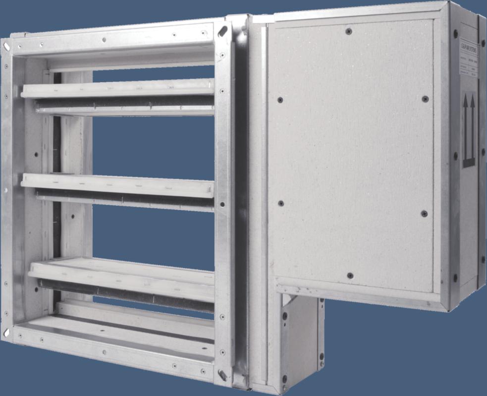
6 MULTIBLADE SMOKE CONTROL DAMPER BRK-J/EI90 DIMENSIONS Fig. 1 Multiblade smoke control damper HOT 400/30 with flange KEY: 1 wall of the housing, opposing the drive 2 wall of the housing, upper / below 3 louver blades, upper / below 4 louver blades, intermediate 5 louver blades with drive axle 6 wall of the housing, drive side 7 protective cover for the frame 8 protective housing for the actuator 9 actuator Tab. 1 Multiblade smoke control damper HOT 400/30 dimensions and weights B x H Weight Aeff [m 2 ] Actuator type B x H Weight Aeff [m 2 ] Actuator type B x H Weight Aeff [m 2 ] Actuator type 200 x ,80 0,0098 BLE 500 x ,30 0,0257 BLE 800 x ,70 0,0416 BLE 200 x ,80 0,0290 BLE 500 x ,70 0,0761 BLE 800 x ,70 0,1232 BLE 200 x ,70 0,0483 BLE 500 x ,20 0,1266 BLE 800 x ,60 0,2049 BLE 200 x ,70 0,0675 BLE 500 x ,60 0,1770 BLE 800 x ,50 0,2865 BLE 200 x ,70 0,0868 BLE 500 x ,10 0,2275 BLE 800 x ,50 0,3682 BLE 200 x ,70 0,1060 BE 500 x ,50 0,2779 BE 800 x ,40 0,4498 BE 200 x ,70 0,1252 BE 500 x ,00 0,3283 BE 800 x ,30 0,5314 BE 300 x ,30 0,0151 BLE 600 x ,70 0,0310 BLE 900 x ,20 0,0469 BLE 300 x ,70 0,0447 BLE 600 x ,70 0,0918 BLE 900 x ,60 0,1389 BLE 300 x ,20 0,0744 BLE 600 x ,60 0,1527 BLE 900 x ,10 0,2310 BLE 300 x ,70 0,1040 BLE 600 x ,60 0,2135 BLE 900 x ,50 0,3230 BLE 300 x ,20 0,1337 BLE 600 x ,50 0,2744 BLE 900 x ,90 0,4151 BLE 300 x ,60 0,1633 BE 600 x ,50 0,3352 BE 900 x ,30 0,5071 BE 300 x ,10 0,1929 BE 600 x ,40 0,3960 BE 900 x ,80 0,5991 BE 400 x ,80 0,0204 BLE 700 x ,20 0,0363 BLE 1000 x ,70 0,0522 BLE 400 x ,70 0,0604 BLE 700 x ,70 0,1075 BLE 1000 x ,60 0,1546 BLE 400 x ,70 0,1005 BLE 700 x ,10 0,1788 BLE 1000 x ,50 0,2571 BLE 400 x ,70 0,1405 BLE 700 x ,60 0,2500 BLE 1000 x ,50 0,3595 BLE 400 x ,60 0,1806 BLE 700 x ,00 0,3213 BLE 1000 x ,40 0,4620 BLE 400 x ,60 0,2206 BE 700 x ,40 0,3925 BE 1000 x ,30 0,5644 BE 400 x ,60 0,2606 BE 700 x ,90 0,4637 BE 1000 x ,20 0,6668 BE Tab. 2 Classification of the smoke control damper BRK-J/EI90/M in accordance to EN EI 90 (vedw - hodw i o) S1000 C10000 HOT 400/300 AAmulti Installation location / supporting construction Wall / ceiling Classification Minimum thickness [mm] In front of the Solid ceiling EI 90 (hod i o) S1000C10000 HOT 400/30 AAmulti Solid ceilings 150 EI 90 (how i o) S1000C10000 HOT 400/30 AAmulti Solid wall construction 100 EI 90 (vew i o) S1000C10000 HOT 400/30 AAmulti Lightweight wall (fire resistant paneling) 100 EI 90 (vew i o) S1000C10000 HOT 400/30 AAmulti In front of the Solid wall construction EI 90 (ved i o) S1000C10000 HOT 400/30 AAmulti In front of the lightweight wall (fire resistant paneling) EI 90 (ved i o) S1000C10000 HOT 400/30 6 6

7 MULTIBLADE MULTIBLADE SMOKE CONTROL DAMPER BRK-J/EI90 DESIGN / INSTALLATION Tab. 3 Design BRK-J/EI90/M Damper design: Smoke control damper with BLE 24 Smoke control damper with BLE 24-ST Smoke control damper with BE 24 Smoke control damper with BE 24-ST Smoke control damper with BLE 230 Smoke control damper with BE 230 Smoke control damper with Smoke control damper with ST Smoke control damper with Smoke control damper with ST Smoke control damper with Smoke control damper with ST Smoke control damper with Smoke control damper with Smoke control damper with Installation: BRK-J/EI90/[BxH]/M M22 M23 M25 M26 M28 M30 G22 G23 G24 G25 G26 G27 G28 G29 G30 General information for the multiblade smoke control dampers!!attention!! There is a risk of injury upon edges and sheet metal parts. During transport and installation, always wear protective gloves. The multiblade smoke control damper BRK-J/EI90/M/HOT is assigned for the installation in the ducts for the heat and combustion gases control, in accordance to EN The wiring (connection of the actuator) must be produced by an authorized electrician, according to the current standards instructions. Thereby, an appropriate drill hole must be made in the insulated housing that is as big as E90 / E30. The E 90 / E 30 cable must be led in insulated housing, the gap must be sealed with fire resistant joint compound or fire resistant silicone. In front of the insulated housing a strain relief must be made. Installation position: The multiblade smoke control damper - BRK-J/EI90/M/HOT is suitable for the installation in vertical or horizontal position with random blade position. The applicable direction arrows on the housing must always point upwards or horizontal. Airflow is horizontally and vertically possible, inflow or outflow side of the air is not important. Actuator on the right (default) or on the left. The position of the axis can be vertical or horizontal! By the vertical axis, the actuator can be above or under. The multiblade smoke control dampers can be installed in vertical as well as in horizontal fire protective section. The multiblade smoke control dampers must be completely volt-free, right-angled and precisely installed. Sufficient room must be provided for maintenance and cleaning on the multiblade smoke control damper. An access opening must be provided for cleaning purposes of the multiblade smoke control dampers. The multiblade smoke control dampers are tested in accordance to the EN Multi Compartment specifications. The distance between the smoke damper and the supporting structure (wall, ceiling) must be minimally 75 mm. If two or more smoke dampers should be installed in one sector, then the distance between the juxtaposed dampers must be at least 200 mm. Fig. 2: The distance between the multiblade smoke damper and the structures required by EN normative. During the installation, the damper blade must be in "closed" position always. The damper in the fire protective isolating structure must be mounted in accordance to fig. 31. If this solution is not possible, the ventilation duct must be protected between the fire protective isolating structure and the damper blade in accordance to the certified installation type (see table 4- Installation type overview) and for the exact details for the additional insulation taken from the actual installation diagram and fig. 32. It is important to protect the actuator with a cover against damage and contamination, as long as the wall construction and plastering have not yet been carried out. The damper housing must not be deformed during the wall construction. After the damper installation, the damper blade must not ream against the housing during opening or closing. Installation with soft seal: During the installation with soft seal the specifications of the soft seal manufacturer (e.g. HILTI) must be regarded. It has to have equivalent material properties in case that other brands of soft seals shall be used due to some reason. Installation conditions must be satisfied in all cases as mandatory requirement! The soft seal must have the size of W x H = 1650 x 2050 mm or W x H = 2050 x 1650 mm. The maximum edge distance must not exceed 400 mm. If the size, in accordance to ETA / ETA tested, of blank seal is not exceeded, then there are no specifications for the maximum edge distance. Firestop boards: Brand HILTI Firestop Board CFS-CT B 1S 140/50 Coating: Brand HILTI Firestop Coating CFS-CT Boards bonding: Brand HILTI Acrylic Sealant CFS-S ACR 7 7
8 MULTIBLADE SMOKE CONTROL DAMPER BRK-J/EI90/M/HOT INSTALLATION The lightweight walls must be prepared by the way that they do not sway the function of the soft seal over the fire resistance period. Lightweight walls must not affect the function of the isolation over the fire resistance period, even in case of possible deformation in the event of fire. (e.g. damage / displacement of the isolation relating to the fire damper/ smoke control damper due to deflection of the wall in the event of fire. When installing more fire dampers, the following points must be considered: The given measurements are based on the installation with the HILTI products. If other brands of soft seals are used, it has to have equivalent material properties and installation conditions must be satisfied! If the size of the soft seal is bigger than the size tested in accordance to ETA / ETA, then the maximum edge distance must not exceed 400 mm. Also, in a seal could be combined the dampers with horizontal and vertical axis. The multiblade smoke control dampers can be installed outside of the wall, or ceiling construction. The ventilation duct and a part of the damper, between the wall structure and the damper blade, must be protected with an fire insulation (see also fig. 11). The allowed types of installation are given in the table 4 and in the corresponding illustrations of the instructions for the additional insulation. By the installation outside of the wall structure or inside the opening, damper must not hang on by its own weight. See fig. 34 and fig. 35. The installation of the multiblade smoke control damper must be provided according to installation conditions. The fastening, in the event of fire, endures the whole fire resistance period (90 min) and the displacement of the damper is excluded. The multiblade smoke control damper must be installed without deformations or damages. The right-angled installation must by secured. Free movement shall be checked after the installation. In this context, for the installation of the multiblade smoke control damper shall generally be recommended the usage of expansion compensators, in order to, alternatively, compensate, on the one hand the twisting of the housing, on the other hand, in the event of fire occurring expansion of the line and out of it resulting energy. The expansion compensators on their deployment must exhibit the same integrity as the smoke control damper! The remaining gap between the multiblade smoke control damper and fire protective isolating structure must be sealed correspondingly to the chosen type of installation. In any case it should be ensured, that the fire resistance of the whole structure (wall / ceiling / fire damper) is not reduced by installing in any way. The mounting, maintenance and control of the operating capability must be done by an expert in accordance to directions as well as installation requirements. For the reliable operation of the multiblade smoke control dampers is important to note, that it does not come to obstruction of the closing mechanism and the sealing surface of the damper blades through dust, fibrous or sticky materials and solvent. Control of the damper actuator without power supply: It is possible to manually adjust the damper blade in every position using the special wrench (actuator's accessory). By turning the wrench in the arrow direction, the damper blade is moving in the open position. The damper blade stays in optimal position. Commission and control of efficiency: After the installation, the movement of the damper blades must be checked for the smooth-running. If, for any reason, the damper function cannot be ensured, then this must be explicitly noted. The operator must ensure that the multiblade smoke control damper will be brought into the state, in which it can again fulfill its function, and during this time, he must ensure fire safety in another adequate manner. There are two types of installation of the smoke control dampers: - Installation with the expansion compensation - Installation without the expansion compensation By the installation of the multiblade smoke control dampers installation requirements must be regarded. Minimal dimensions of the openings: The exact dimensions must be set and agreed with the seal manufacturer, the company that undertakes the first concrete works usually. The minimal dimensions are to be found in the fig. 1. They are placed on pressed mortar procedure. Flange: The flange of the square dampers have in the corners the elongated holes (Fig. 3). The smoke control damper can only be connected with elastic fasteners on the ventilation ducts if they do not lose their intended function under fire exposure. No detachable equipotential bonding is required for the smoke control damper. When connecting the smoke control dampers the ventilation ducts, the fire protective effect of the ventilation duct must not be affected in case of fire by the elastic fastener. Fig. 3 Flange BRK-J/EI90/M/HOT 8 8
9 MULTIBLADE SMOKE CONTROL DAMPER BRK-J/EI90/M/HOT INSTALLATION Description of the installation types - SOLID WALLS and SOLID CEILINGS: Solid walls / Solid ceilings - Concrete Walls/Ceilings - Aerated concrete walls / ceilings - Brick walls - Walls of gypsum blocks according to EN (without caverns) Preconditions: - Wall thickness: w 100 mm - Ceiling thickness: d 150 mm - Wall density: 500 kg/m - Ceiling density: 600 kg/m - The distance between the multiblade smoke control damper and the structural components: min The distance between two smoke control dampers: min. 200 mm Wet installation The multiblade smoke control damper can be installed inside the slid walls with an all-around mortaring. By wet installation, the slots (caverns) between the damper and the wall or ceiling must be completely filled in. Caverns must be prevented. The depth of the mortar must never be less than 100 mm. Allowed mortar - Shrinkage crack-optimized fire resistant mortar - Concrete Drywall installation Installation in fire protective seal with putty and fireproof board. Description of the installation types - LIGHTWEIGHT WALLS Lightweight walls - Walls with metal rack and two-sided paneling with European classification corresponding to EN Preconditions: - Wall thickness: w 100 mm - The distance between the multiblade smoke control damper and the structural components: min The distance between two smoke control dampers: min. 200 mm Description of the installation types outside of the fire protective isolating structure: The multiblade smoke control damper can be installed outside of the wall / ceiling construction. The ventilation duct and the part of the multiblade smoke control damper, between the wall structure and the damper blade, must be protected with a fire insulation. General instructions for installation: The damper in the fire protective isolating structure must be in accordance to fig. 30 mounted. If this solution is not possible, the ventilation duct must be protected between the fire protective isolating structure and the damper blade in accordance to the certified installation type (see tab. 4 - Installation type overview) and for the exact details for the additional insulation take from the actual installation diagram and fig. 31. The connection of the multiblade smoke control damper with the smoke control duct for multi compartments (EN and EN ) must be clarified with the manufacturer of smoke control ducts! 9 9

, max.400 seals are used, it has to have equivalent material properties and installation conditions must be satisfied!")
10 MULTIBLADE SMOKE CONTROL DAMPER BRK-J/EI90/M/HOT INSTALLATION WITH SOFT SEAL There are two types of installation of the smoke control dampers: - Installation with the expansion compensation - Installation without the expansion compensation Installation requirements must be regarded by the installation of dampers. Installation with soft seal: During the installation with soft seal, the specifications of the soft seal manufacturer (e.g. HILTI) must be regarded.. If other brands of soft Weichschott maximal 2050 min.30 (Flange), max.400 seals are used, it has to have equivalent material properties and installation conditions must be satisfied! The soft seal must have the size of W x H = 1650 x 2050 mm or W x H = 2050 x 1650 mm. The maximum edge distance must not exceed 400 mm. If the size, in accordance to ETA / ETA tested, of blank seal is not exceeded, then there are no specifications for the maximum edge distance. Example for several dampers in a seal - please check the fig. 6 and 7.By the minimum measurements please regard the size of the BRK- J/EI90/M/HOT flange of 30 mm! HILTI soft seal: Maximum dimensions 2050 x 1650 mm, or 1650 x 2050 mm min.30 (Flange), max.400 Weichschott maximal 1650 min.30 (Flange), max.400 Firestop boards: Brand HILTI Firestop Board CFS-CT B 1S 140/50 Coating: Brand HILTI Firestop Coating CFS-CT Bonding of boards: Brand HILTI Acrylic Sealant CFS-S ACR If other brands of soft seals are used, it has to have equivalent material properties and installation conditions must be satisfied! Smaller dimensions in the Fig. 4 and 5 come from the individual mounting through the maximal dimensions of the damper. If the size, tested in accordance to ETA, of blank seal is not exceeded, then there are no specifications for the maximum edge distance. The minimal distance must be clarified with the particular soft seal manufacturer! The lightweight walls must be so implemented so that they do not sway the function of the soft seal over the fire resistance period. Lightweight walls must not affect the function of the isolation over the fire resistance period, even in case of possible deformation in the event of fire. (e.g. damage / displacement of the isolation relating to the fire damper / smoke control damper due to deflection of the wall in the event of fire. min.30 (Flange), max.400 Fig. 4 Multiblade smoke control dampers BRK-J/EI90/M/HOT in soft seal (brand HILTI) with horizontal axis Weichschott maximal 1650 min.30 (Flange), max.400 min.30 (Flange), max.400 min.30 (Flange), max.400 Weichschott maximal 2050 min.30 (Flange), max.400 Fig. 5 Multiblade smoke control dampers BRK-J/EI90/M/HOT in soft seal (brand HILTI) with vertical axis, actuator can be above or under 10 10


11 MULTIBLADE SMOKE CONTROL DAMPER BRK-J/EI90/M/HOT INSTALLATION WITH SOFT SEAL COMBINED PENETRATION SEAL When installing more dampers, the following points must be considered: min.30 (Flange), max.400 The given measurements are based on the installation with the HILTI products. If other brands of soft seals are used, it has to have equivalent material properties and installation conditions must be satisfied! If the size of the soft seal is bigger than the size tested in accordance to ETA / ETA, then the maximum edge distance must not exceed 400 mm. Also, in a seal could be combined the dampers with horizontal and vertical axis. min.30 (Flange), max.400 min.30 (Flange), max.400 min.30 (Flange), max.400 The soft seal must have the size of W x H =1650 x 2050 mm or W x H = 2050 x 1650 mm. The maximum edge distance must not surpass 400 mm. If the size, in accordance to ETA / ETA tested, of blank seal is not exceeded, then there are no specifications for the maximum edge distance. The minimal distance must be clarified with the particular soft seal manufacturer! Fig. 6 multiblade smoke control dampers BRK-J/EI90/M/HOT in soft seal (brand HILTI) with horizontal axis (brand HILTI) min.30 (Flange), max.400 min.30 (Flange), max.400 min.30 (Flange), max.400 min.30 (Flange), max.400 Fig. 7 Multi-part multiblade smoke control dampers BRK-J/EI90/M/HOT in soft seal (brand HILTI) with vertical axis, actuator can be above or under (brand HILTI) 11 11

12 MULTIBLADE SMOKE CONTROL DAMPER BRK-J/EI90/M/HOT INSTALLATION WITH SOFT SEAL SINGLE-SIDED THIN SHAFT WALLS Installation with soft seal in light, single-sided covered thin shaft walls Apart from the proper forming of the opening embrasure, the wall deformations under fire load must be regarded for the fire dampers, which are, for the installation with soft seal in accordance to EN and national proposal for the soft seal checkup in accordance to EN , classified, and which should be installed in single-sided covered lightweighted thin shaft walls. In order to achieve no reduction through these wall deformations of the whole- fire resistance of the wall-components-soft seal- combination, the installation in such wall systems requires special methods, that are hereinafter explained. They apply on the fire dampers with test validation in two-sided covered lightweight walls as well as on the single-sided covered lightweight walls, by deploying a soft seal system for the closure of the gap. Since the single-sided paneled thin shaft walls are not the standard support structure and in accordance to EN , the solution that is without any additional test certificate, can be applied, as required by practice, on the basis of orienting fire tests, whereby the following specifications for clear shaft widths "B" apply to maximal 4,0 m and a certificate for the soft seal as blank seal exists in corresponding size and construction. Should the opening size in installation section exceed the allowed size of the blank seal, a structural separation (e.g. minimum 40 mm fire protection panel / silicate) must be provided. A solid wall (e.g. aerated concrete) can replace the singe-sided paneled thin shaft wall, whereby a standard situation is accomplished without additionally required methods. Splitting a lighter, single-sided paneled thin shaft walls in two areas The installation of the fire dampers and smoke control damper in light, single-sided paneled thin shaft walls with soft seal jointing of the remaining areas of the opening requires the separation of the installed (fire dampers / smoke control dampers, also pipes, ducts and cable) from the wall structure itself, and creation of the separated areas for the wall mounting and the installations. Typical thin shaft wall situation with installation area, beam and wall area. Floor Installation area Division Wall Shaft area side wall Shaft side wall Floor Fig. 12 Shaft wall - division 12 12
13 MULTIBLADE SMOKE CONTROL DAMPER BRK-J/EI90/M/HOT INSTALLATION WITH SOFT SEAL SINGLE-SIDED THIN SHAFT WALLS Installation of the smoke control damper in single-sided thin shaft walls with soft seal. Fig. 8 Multiblade smoke control dampers EI90 installation in soft seal (brand HILTI) in single-sided thin shaft walls. Installation area Division Structural separation thickness 40 mm Fire resistant plate Wall area Shaft side wall Shaft side wall Floor Shaft area Profil 70x70x4mm The multiblade fire damper is tested with the soft seal brand HILTI.. If other brands of soft seals are used, it has to have equivalent material properties and installation conditions must be satisfied! The minimal distance must be clarified with the particular soft seal manufacturer / fabricator! Should the opening size in installation section exceed the allowed size of the blank seal according to ETA / ETA, then a structural separation (e.g. minimum 40 mm fire protection panel / silicate) must be provided. The light thin shaft wall can also be flush mounted with the soft seal and the beam in the utility area! Facing 2x20mm Fire resistant plate Profil Light wall plates U50/CW
14 MULTIBLADE SMOKE CONTROL DAMPER BRK-J/EI90 INSTALLATION TYPES Installation type overview: The smoke control damper BSK-J/EI90/M/HOT is tested in accordance to the EN requirements. Smoke control damper BRK-J/EI90/M/HOT Dimensions CE certificate No. Installation location Minimum thickness [mm] B = mm H = mm 1391-CPR-0092/2014 Installation type Fire resistance Fig. No: Solid walls 100 Wet installation Plaster or mortar AA Drywall installation Soft seal AA 10 Outside of Solid wall 100 Drywall installation Insulation with mineral wool AA 11 On the Solid walls 100 Drywall installation Insulation with mineral wool AA 12 Solid ceilings 150 Wet installation Plaster or mortar AA Drywall installation Soft seal AA 14 Outside of the Solid ceiling 150 Drywall installation Insulation with mineral wool AA 15 On the Solid ceiling 150 Drywall installation Insulation with mineral wool AA 16 Lightweight wall 100 Drywall installation Soft seal AA 17 Outside of the lightweight wall 100 Drywall installation Insulation with mineral wool AA 18 On the lightweight walls 100 Drywall installation Insulation with mineral wool AA 19 Horizontal smoke control duct 1) Drywall installation According to documentation AA 20 Vertical smoke control duct 1) Drywall installation According to documentation AA 21 On the horizontal smoke control ducts 1) horizontal Drywall installation According to documentation AA 22 On the horizontal smoke control ducts 1) vertical Drywall installation According to documentation AA 23 On the horizontal smoke control ducts 1) Drywall installation According to documentation AA 24 Single-sided thin shaft walls Drywall installation Soft seal AA 25 Installation without connection to the smoke control duct, flow into EI90 "multi compartment" smoke control duct provided by the customer Solid walls 100 Wet installation Plaster or mortar AA Drywall installation Soft seal AA 27 Solid ceilings 150 Wet installation Plaster or mortar AA Drywall installation Soft seal AA 29 Lightweight wall 100 Drywall installation Soft seal AA 30 Table 4 Overview installation types of smoke control dampers BRK-J/EI90/M/HOT AA corresponds to EI 90 (vedw - hodw i o) S1000 C10000 HOT 400/300 AAmulti 1) Smoke control ducts for multiple compartments (EN and EN )


15 MULTIBLADE SMOKE CONTROL DAMPER INSTALLATION DETAILS IN SOLID WALLS Inside solid walls Multiblade smoke control damper installed in solid wall construction of minimum thickness 100 mm in plaster or mortar - fire resistance class Fig. 9 The surface between the smoke control dampers, housing of the damper and the calcium-silicate boards must be furnished with PROMAT K84 adhesive. The connection of the multiblade smoke control damper with the smoke control duct for multi compartments (EN and EN ) must be clarified with the particular manufacturer of the smoke control ducts! The fastening of the multiblade smoke control damper must always be done in accordance to installation requirements. KEY: 1 Multiblade smoke control damper BRK-J/EI90/M/HOT 2 Plaster or mortar (e.g. shrinkage crack-optimized fire resistant mortar) 3 Horizontal smoke control ducts for multi compartments (EN and EN ) 4 Soft seal brand HILTI 5 Coating brand HILTI 6 Insulation made of calcium-silicate boards min. volume weight 450 kg/m³ Thickness 40 mm Example of the used materials*: 4 HILTI Firestop Board CFS-CT B 1S 140/50 5 HILTI Firestop Coating CFS-CT * On the materials for the fire protective seal, putty, fireproof boards and insulation materials, it is possible to replace them with a similar approved system with correspondent qualities. In solid walls Multiblade smoke control damper installed in solid wall structure of minimum thickness 100 mm in soft seal system - fire resistance class Fig. 10 The surface between the smoke control dampers, housing of the damper and the calcium-silicate boards must be furnished with PROMAT K84 adhesive. Surface between the insulation (5) and the soft seal must be furnished with HILTI Acrylic Sealant CFS-S ACR. The connection of the multiblade smoke control damper with the smoke control duct for multi compartments (EN and EN ) must be clarified with the manufacturer of smoke control ducts! The fastening of the multiblade smoke control damper must always be done in accordance to installation requirements The soft seal maximal dimensions W x H = 1650 x 2050 mm or W x H = 2050 x 1650 mm. The maximum edge distance must not surpass 400 mm. If the size, in accordance to ETA / ETA tested, of blank seal is not exceeded, then there are no specifications for the maximum edge distance. KEY: 1 Multiblade smoke control damper BRK-J/EI90/M/HOT 2 Soft seal brand HILTI 3 Coating brand HILTI 4 Horizontal smoke control ducts for multi compartments (EN and EN ) 5 Insulation made of calcium-silicate boards min. volume weight 450 kg/m³ Thickness 40 mm Example of the used materials*: 2 HILTI Firestop Board CFS-CT B 1S 140/50 1) 3 HILTI Firestop Coating CFS-CT 1) Boards bonding: Brand HILTI Acrylic Sealant CFS-S ACR If other brands of soft seals are used, it has to have equivalent material properties and installation conditions must be satisfied! 15 15


16 MULTIBLADE SMOKE CONTROL DAMPERS INSTALLATION DETAILS OUTSIDE OF AND ON THE SOLID WALL Multiblade smoke control damper outside of the solid wall: Multiblade smoke control damper installed outside of solid wall construction of minimum thickness 100 mm - Air line duct is sealed with fire protective seal with putty and fireproof boards - The airline is additionally insulated with a CONLIT Ductrock system or with similar approved system. - Isolation of the fire resistance class Fig. 11 The surface between the smoke control dampers, housing of the damper and the calcium-silicate boards must be furnished with PROMAT K84 adhesive. The connection of the multiblade smoke control damper with the smoke control duct for multi compartments (EN and EN ) must be clarified with the particular manufacturer of the smoke control ducts! The fastening of the multiblade smoke control damper must always be done in accordance to installation requirements. Multiblade smoke control damper installed on the solid walls: Multiblade smoke control damper installed on the solid wall structure of minimum thickness 100 mm - Air line duct is sealed with fire protective seal with putty and fire proof boards - The airline is additionally insulated with a CONLIT Ductrock system or with similar approved system. - Isolation of the fire resistance class Fig. 12 The surface between the smoke control dampers, housing of the damper and the calcium-silicate boards must be furnished with PROMAT K84 adhesive. The connection of the multiblade smoke control damper with the smoke control duct for multi compartments (EN and EN ) must be clarified with the particular manufacturer of the smoke control ducts! The fastening of the multiblade smoke control damper must always be done in accordance to our installation requirements. KEY: 1 Multiblade smoke control damper BRK-J/EI90/M/HOT 2 Mineral rock wool of 140 kg/m³ volume weight 3 Putty thickness 1 mm 4 Fireproof boards (cement-limestone-board) 15 mm thick and 870 kg/m³ volume weight 5 Rockwool bound with organic resin, which contains non-toxic fine flare such as cooling agent, with fire resistance class, minimum volume weight 300 kg/m³, 2 x 60 mm thickness 6 Ventilation duct with horizontal smoke control pipeline for multi compartments (EN and ) covered, on the other side 7 Horizontal smoke control ducts for multi compartments (EN and EN ) 8 Insulation made of calcium-silicate boards min. volume weight 450 kg/m³ Thickness 40 mm Example of the used materials*: 2 Promapyr, Rockwool Steprock HD 3 Promastop - P, K 4 Promatect - H 5 Rockwool Conlit Ductrock, 2 x 60 mm thickness * On the materials for the fire protective seal, putty, fire proof boards and insulation materials, it is possible to replace them with a similar approved system with correspondent qualities. Example of the used materials*: 16 16

17 MULTIBLADE SMOKE CONTROL DAMPER INSTALLATION DETAILS IN SOLID CEILING In solid ceiling Multiblade smoke control damper installed in solid ceiling structure of minimum thickness 100 mm in plaster or mortar - fire resistance class Fig. 13 The surface between the smoke control dampers, housing of the damper and the calcium-silicate boards must be furnished with PROMAT K84 adhesive. The connection of the multiblade smoke control damper with the smoke control duct for multi compartments (EN and EN ) must be clarified with the particular manufacturer of the smoke control ducts! The fastening of the multiblade smoke control damper must always be done in accordance to our installation requirements. KEY: 1 Multiblade smoke control damper BRK-J/EI90/M/HOT 2 Plaster or mortar (e.g. shrinkage crack-optimized firestop mortar) 3 Vertical smoke control ducts for multi compartments (EN and EN ) 4 Insulation made of calcium-silicate boards min. volume weight 450 kg/m³ Thickness 40 mm 5 Soft seal brand HILTI 6 Covering brand HILTI Fig. 14 Example of the used materials*: 5 HILTI Firestop Board CFS-CT B 1S 140/50 6 HILTI Firestop Coating CFS-CT * On the materials for the fire protective seal, putty, fireproof boards and insulation materials, it is possible to replace them with a similar approved system with correspondent qualities. The surface between the smoke control dampers, housing of the damper and the calcium-silicate boards must be furnished with PROMAT K84 adhesive. Surface between the insulation (5) and the soft seal must be furnished with HILTI Acrylic Sealant CFS-S ACR. The connection of the multiblade smoke control damper with the smoke control duct for multi compartments (EN and EN ) must be clarified with the particular manufacturer of the smoke control ducts! The fastening of the multiblade smoke control damper must always be done in accordance to our installation requirements. KEY: 1 Multiblade smoke control damper BRK-J/EI90/M/HOT 2 Soft seal brand HILTI 3 Coating brand HILTI 4 Vertical smoke control ducts for multi compartments (EN and EN ) 5 Insulation made of calcium-silicate boards min. volume weight 450 kg/m³ Thickness 40 mm Example of the used materials*: 2 HILTI Firestop Board CFS-CT B 1S 140/50 1) 3 HILTI Firestop Coating CFS-CT 1) Bonding of boards: Brand HILTI Acrylic Sealant CFS-S ACR If other brands of soft seals are used, it has to have equivalent material properties and installation conditions must be satisfied! The soft seal maximal dimensions W x H = 1650 x 2050 mm or W x H = 2050 x 1650 mm. The maximum edge distance must not exceed 400 mm. If the size, in accordance to ETA / ETA tested, of blank seal is not exceeded, then there are no specifications for the maximum edge distance

 must be clarified with the particular manufacturer of the smoke")
18 MULTIBLADE SMOKE CONTROL DAMPERS INSTALLATION DETAILS OUTSIDE OF AND ON THE SOLID CEILING Multiblade smoke control damper installed outside of the solid ceiling - Air line duct is sealed with plaster or mortar - The airline is additionally insulated with a CONLIT Ductrock system or with similar approved system. - Isolation of the fire resistance class Fig. 15 The surface between the smoke control dampers, housing of the damper and the calcium-silicate boards must be furnished with PROMAT K84 adhesive. The connection of the multiblade smoke control damper with the smoke control duct for multi compartments (EN and EN ) must be clarified with the particular manufacturer of the smoke control ducts! The fastening of the multiblade smoke control damper must always be done in accordance to our installation requirements. Multiblade smoke control damper installed on the solid ceiling - Airline duct is sealed with plaster or mortar - The airline is additionally insulated with a CONLIT Ductrock system or with similar approved system. - Isolation of the fire resistance class Fig. 16 The surface between the smoke control dampers, housing of the damper and the calcium-silicate boards must be furnished with PROMAT K84 adhesive. The connection of the multiblade smoke control damper with the smoke control duct for multi compartments (EN and EN ) must be clarified with the particular manufacturer of the smoke control ducts! The fastening of the multiblade smoke control damper must always be done in accordance to our installation requirements. KEY: 1 Multiblade smoke control damper BRK-J/EI90/M/HOT 2 Plaster or mortar (e.g. shrinkage crack-optimized firestop mortar) 3 Rock wool bound with organic resin, which contains non-toxic fine flare such as cooling agent, with fire resistance class, minimum volume weight 300 kg/m³, 2 x 60 mm thickness 4 Ventilation duct with horizontal smoke control pipeline for multi compartments (EN and ) covered, on the other side 5 Vertical smoke control ducts for multi compartments (EN and EN ) 6 Insulation made of calcium-silicate boards min. volume weight 450 kg/m³ Thickness 40 mm Example of the used materials*: 3 Rockwool Conlit Ductrock, 2 x 60 mm thickness * On the materials for the fire protective seal, putty, fireproof boards and insulation materials, it is possible to replace them with a similar approved system with correspondent qualities

19 MULTIBLADE SMOKE CONTROL DMAPER INSTALLATION DETAILS IN LIGHTWEIGHT WALLS In lightweight walls: Multiblade smoke control damper installed in a lightweight wall (fire resistant covering) minimum 100 mm thick, fire resistance ability EI 90 in soft seal system - fire resistance class Fig. 17 KEY: 1 Multiblade smoke control damper BRK-J/EI90/M/HOT 2 Soft seal brand HILTI 3 Coating brand HILTI 4 Horizontal smoke control duct for multi compartments (EN and ) 5 Insulation made of calcium-silicate boards min. volume weight 450 kg/m³ Thickness 40 mm Example of the used materials*: 2 HILTI Firestop Board CFS-CT B 1S 140/50 1) 3 HILTI Firestop Coating CFS-CT 1) Boards bonding: Brand HILTI Acrylic Sealant CFS-S ACR If other brands of soft seals are used, it has to have equivalent material properties and installation conditions must be satisfied! The soft seal maximal dimensions W x H =1650 x 2050 mm or W x H = 2050 x 1650 mm. The maximum edge distance must not exceed 400 mm. If the size, in accordance to ETA / ETA tested, of blank seal is not exceeded, then there are no specifications for the maximum edge distance. Lightweight walls must not affect the function of the insulation over the fire resistance period, even in case of possible deformation in the event of fire. The surface between the smoke control dampers, housing of the damper and the calcium-silicate boards must be furnished with PROMAT K84 adhesive. The surface between the insulation (5) and the soft seal must be furnished with HILTI Acrylic Sealant CFS-S ACR. The connection of the multiblade smoke control damper with the smoke control duct for multi compartments (EN and EN ) must be clarified with the particular manufacturer of the smoke control ducts! The fastening of the multiblade smoke control damper must always be done in accordance to installation requirements

 must be clarified with the particular manufacturer of the smoke")
20 MULTIBLADE SMOKE CONTROL DAMPERS OUTSIDE OF AND ON THE LIGHTWEIGHT WALL Multiblade smoke control damper outside of the lightweight wall (fire resistant paneling) fire resistance EI 90 - Air line duct is sealed with fire protective seal with putty and fireproof boards - The airline is additionally insulated with a CONLIT Ductrock system or with similar approved system. - Isolation of the fire resistance class Fig. 18 The surface between the smoke control dampers, housing of the damper and the calcium-silicate boards must be furnished with PROMAT K84 adhesive. The connection of the multiblade smoke control damper with the smoke control duct for multi compartments (EN and EN ) must be clarified with the particular manufacturer of the smoke control ducts! The fastening of the multiblade smoke control damper must always be done in accordance to our installation requirements. Lightweight walls must not affect the function of the insulation over the fire resistance period, even in case of possible deformation in the event of fire. Multiblade smoke control damper on the lightweight wall (fire resistant paneling) fire resistance EI 90 - Air line duct is sealed with fire protective seal with putty and fireproof boards - The airline is additionally insulated with a CONLIT Ductrock system or with similar approved system. - Isolation of the fire resistance class Fig. 19 The surface between the smoke control dampers, housing of the damper and the calcium-silicate boards must be furnished with PROMAT K84 adhesive. The connection of the multiblade smoke control damper with the smoke control duct for multi compartments (EN and EN ) must be clarified with the particular manufacturer of the smoke control ducts! The fastening of the multiblade smoke control damper must always be done in accordance to our installation requirements. Lightweight walls must not affect the function of the insulation over the fire resistance period, even in case of possible deformation in the event of fire. KEY: 1 Multiblade smoke control damper BRK-J/EI90/M/HOT 2 Mineral rock wool of 140 kg/m³ volume weight 3 Putty thickness 1 mm 4 Fireproof boards (cement-limestone-board) 15 mm thick and 870 kg/m³ volume weight 5 Rock wool bound with organic resin, which contains non-toxic fine flare such as cooling agent, with fire resistance class, minimum volume weight 300 kg/m³, 2 x 60 mm thickness 6 Ventilation duct with horizontal smoke control pipeline for multi compartments (EN and ) covered, on the other side 7 Horizontal smoke control duct for multi compartments (EN and ) 8 Insulation made of calcium-silicate boards min. Volume weight 450 kg/m³ Thickness 40 mm Example of the used materials*: 2 Promapyr, Rockwool Steprock HD 3 Promastop - P, K 4 Promatect - H 5 Rockwool Conlit Ductrock, 2 x 60 mm thickness * On the materials for the fire protective seal, putty, fireproof boards and insulation materials, it is possible to replace them with a similar approved system with correspondent qualities
. Fig.")
 3 Insulation made of calcium-silicate boards min. Volume weight 450 kg/m³ Thickness 40 mm 4 Insulation made of calcium-silicate boards min.")
21 MULTIBLADE SMOKE CONTROL DAMPER INSTALLATION DETAILS IN HORIZONTAL AND VERTICAL SMOKE CONTROL DUCT Multiblade smoke control damper installed in horizontal smoke control ducts for multi compartments (EN and EN ). Fig. 20 Multiblade smoke control damper installed in vertical smoke control ducts for multi compartments (EN and EN ). Fig. 21 Key: 1 Multiblade smoke control damper BRK-J/EI90/M/HOT 2 Smoke control ducts for multi compartments (EN and EN ) 3 Insulation made of calcium-silicate boards min. Volume weight 450 kg/m³ Thickness 40 mm 4 Insulation made of calcium-silicate boards min. Volume weight 450 kg/m³ Thickness 40 mm The surface between the smoke control dampers, housing of the damper and the calcium-silicate boards must be furnished with PROMAT K84 adhesive. The connection of the multiblade smoke control with the smoke control duct for multi compartments (EN and EN ) must be clarified with the particular manufacturer of the smoke control ducts! The fastening of the multiblade smoke control damper must always be done in accordance to installation requirements
 horizontal. Fig.")
 3 Insulation made of calcium-silicate boards min.")
22 MULTIBLADE SMOKE CONTROL DAMPER INSTALLATION DETAILS IN HORIZONTAL SMOKE CONTROL DUCT Multiblade smoke control damper installed in horizontal smoke control ducts for multi compartments (EN and EN ) horizontal. Fig. 22 Multiblade smoke control damper installed in horizontal smoke control ducts for multi compartments (EN and EN ) vertical. Fig. 23 Key: 1 Multiblade smoke control damper BRK-J/EI90/M/HOT 2 Smoke control ducts for multi compartments (EN and EN ) 3 Insulation made of calcium-silicate boards min. volume weight 450 kg/m³ Thickness 40 mm The surface between the smoke control dampers, housing of the damper and the calcium-silicate boards must be furnished with PROMAT K84 adhesive. The connection of the multiblade smoke control damper with the smoke control duct for multi compartments (EN and EN ) must be clarified with the particular manufacturer of the smoke control ducts! The fastening of the multiblade smoke control damper must always be done in accordance to installation requirements
. Fig. 24 Key: 1 Multiblade smoke control damper BRK-J/EI90/M/HOT 2 Smoke control ducts for multi compartments (EN 12101-7 and EN 1366-8) 3 Insulation made of calcium-silicate boards min.")
23 MULTIBLADE SMOKE CONTROL DAMPER INSTALLATION DETAILS IN VERTICAL SMOKE CONTROL DUCT Multiblade smoke control damper installed in vertical smoke control ducts for multi compartments (EN and EN ). Fig. 24 Key: 1 Multiblade smoke control damper BRK-J/EI90/M/HOT 2 Smoke control ducts for multi compartments (EN and EN ) 3 Insulation made of calcium-silicate boards min. volume weight 450 kg/m³, thickness 40 mm The surface between the smoke control dampers, housing of the damper and the calcium-silicate boards must be furnished with PROMAT K84 adhesive. The connection of the multiblade smoke control damper with the smoke control duct for multi compartments (EN and EN ) must be clarified with the particular manufacturer of the smoke control ducts! The fastening of the multiblade smoke control damper must always be done in accordance to installation requirements

24 MULTIBLADE SMOKE CONTROL DAMPER BRK-J/EI90/M/HOT INSTALLATION WITH SOFT SEAL SINGLE-SIDED THIN SHAFT WALLS Multiblade smoke control dampers EI90 installation in soft seal (brand HILTI) in single-sided thin shaft walls Fig. 25 Installation area Division Structural separation thickness 40 mm Fire resistant plate Wall area Shaft side wall Shaft side wall Shaft area Floor Profil 70x70x4mm The multiblade fire damper is tested with the soft seal brand HILTI.. If other brands of soft seals are used, it has to have equivalent material properties and installation conditions must be satisfied! The minimal distance must be clarified with the particular soft seal manufacturer / fabricator! Should the opening size in installation section exceed the allowed size of the blank seal according to ETA / ETA, then a structural separation (e.g. minimum 40 mm fire protection panel / silicate) must be provided. The light thin shaft wall can also be flush mounted with the soft seal and the beam in the utility area! Facing 2x20mm Fire resistant plate Profil Light wall plates U50/CW
.")

25 MULTIBLADE SMOKE CONTROL DAMPER INSTALLATION DETAILS IN SOLID WALLS WITHOUT SMOKE CONTROL DUCT In solid walls Multiblade smoke control damper installed in solid wall structure minimum thickness 100 mm plaster or mortar - fire resistance class without smoke control ducts for multi compartments (EN and EN ). Instead of the smoke control ducts for multi compartments (EN and EN ) there is a SOLID smoke control duct (smoke control shaft) for multi compartments. It must be clarified with the fire expert whether or not the smoke control damper provided by customer can be used! Actuator box insulation (soft seal) must be installed on the side of the shaft, so that the inspection work of the actuator can be done from the other side. Fig. 26 The fastening of the multiblade smoke control damper must always be done in accordance to our installation requirements. * On the materials for the fire protective seal, putty, fireproof boards and insulation materials, it is possible to replace them with a similar approved system with correspondent qualities. KEY: 1 Multiblade smoke control damper BRK-J/EI90/M/HOT 2 Plaster or mortar (e.g. shrinkage crack-optimized fire resistant mortar) 3 Soft seal brand HILTI 4 Coating brand HILTI Example of the used materials*: 3 HILTI Firestop Board CFS-CT B 1S 140/50 4 HILTI Firestop Coating CFS-CT In SOLID walls Multiblade smoke control damper installed in solid wall structure minimum thickness 100 mm plaster or mortar - fire resistance class without smoke control ducts for multi compartments (EN and EN ). Instead of the smoke control ducts for multi compartments (EN and EN ) there is a solid smoke control duct (smoke control shaft) for multi compartments. It must be clarified with the fire expert whether or not the smoke control damper provided by customer can be used! Actuator box insulation (soft seal) must be installed on the side of the shaft, so that the inspection work of the actuator can be done from the other side. Fig. 27 The fastening of the multiblade smoke control damper must always be done in accordance to our installation requirements. If other brands of soft seals are used, it has to have equivalent material properties and installation conditions must be satisfied! KEY: 1 Multiblade smoke control damper BRK-J/EI90/M/HOT 2 Soft seal brand HILTI 3 Coating brand HILTI Example of the used materials*: 2 HILTI Firestop Board CFS-CT B 1S 140/50 1) 3 HILTI Firestop Coating CFS-CT 1) Boards bonding: Brand HILTI Acrylic Sealant CFS-S ACR 25 25
.")

26 MULTIBLADE SMOKE CONTROL DAMPER INSTALLATION DETAILS IN SOLID CEILING WITHOUT SMOKE CONTROL DUCT In solid ceiling Multiblade smoke control damper installed in solid ceiling structure minimum thickness 100 mm plaster or mortar - fire resistance class without smoke control ducts for multi compartments (EN and EN ). Instead of the smoke control ducts for multi compartments (EN and EN ) there is a solid smoke control duct (smoke control shaft) for multi compartments. It must be clarified with the fire expert whether or not the smoke control damper provided by customer can be used! Actuator box insulation (soft seal) must be installed on the side of the shaft, so that the inspection work of the actuator can be done from the other side. Fig. 28 KEY: 1 Multiblade smoke control damper BRK-J/EI90/M/HOT 2 Plaster or mortar (e.g. shrinkage crack-optimized firestop mortar) 3 Soft seal brand HILTI 4 Coating brand HILTI Example of the used materials*: 3 HILTI Firestop Board CFS-CT B 1S 140/50 4 HILTI Firestop Coating CFS-CT The fastening of the multiblade smoke control damper must always be done in accordance to installation requirements. * On the materials for the fire protective seal, putty, fireproof boards and insulation materials, it is possible to replace them with a similar approved system with correspondent qualities. In solid ceiling Multiblade smoke control damper installed in solid ceiling structure minimum thickness 150 mm plaster or mortar - fire resistance class without smoke control ducts for multi compartments (EN and EN ). Instead of the smoke control ducts for multi compartments (EN and EN ) there is a solid smoke control duct (smoke control shaft) for multi compartments. It must be clarified with the fire expert whether or not the smoke control damper provided by customer can be used! Actuator box insulation (soft seal) must be installed on the side of the shaft, so that the inspection work of the actuator can be done from the other side. Fig. 29 KEY: 1 Multiblade smoke control damper BRK-J/EI90/M/HOT 2 Soft seal brand HILTI 3 Coating brand HILTI Example of the used materials*: 2 HILTI Firestop Board CFS-CT B 1S 140/50 1) 3 HILTI Firestop Coating CFS-CT 1) Bonding of boards: Brand HILTI Acrylic Sealant CFS-S ACR The fastening of the multiblade smoke control damper must always be done in accordance to installation requirements. If other brands of soft seals are used, it has to have equivalent material properties and installation conditions must be satisfied! 26 26
 minimum 100 mm thick, fire resistance ability EI 90 in soft seal system - fire resistance class without smoke control ducts for multi compartments (EN 12101-7 und EN 1366-8).")
27 MULTIBLADE SMOKE CONTROL DAMPER INSTALLATION DETAILS IN LIGHTWEIGHT WALLS WITHOUT SMOKE CONTROL DUCT In lightweight walls: Multiblade smoke control damper installed in a lightweight wall (fire resistant paneling) minimum 100 mm thick, fire resistance ability EI 90 in soft seal system - fire resistance class without smoke control ducts for multi compartments (EN und EN ). Instead of the smoke control ducts for multi compartments (EN and EN ) there is a solid smoke control duct (smoke control shaft) for multi compartments. It must be clarified with the fire expert whether or not the smoke control damper provided by customer can be used! Actuator box insulation (soft seal) must be installed on the side of the shaft, so that the inspection work of the actuator can be done from the other side. Fig. 30 KEY: 1 Multiblade smoke control damper BRK-J/EI90/M/HOT 2 Soft seal brand HILTI 3 Coating brand HILTI Example of the used materials*: 2 HILTI Firestop Board CFS-CT B 1S 140/50 1) 3 HILTI Firestop Coating CFS-CT 1) Bonding of boards: Brand HILTI Acrylic Sealant CFS-S ACR If other brands of soft seals are used, it has to have equivalent material properties and installation conditions must be satisfied! The soft seal maximal dimensions W x H =1650 x 2050 mm or W x H = 2050 x 1650 mm. The maximum edge distance must not exceed 400 mm. If the size, in accordance to ETA / ETA tested, of blank seal is not exceeded, then there are no specifications for the maximum edge distance. Lightweight walls must not affect the function of the insulation over the fire resistance period, even in case of possible deformation in the event of fire. The fastening of the multiblade smoke control damper must always be done in accordance to installation requirements
28 MULTIBLADE SMOKE CONTROL DAMPERS INSTALLATION DETAILS INSTALLATION EDGING AND ADDITIONAL ISOLATION EDGING Installation edging (wall construction edging): By installation in the fire protective isolating structure, the multiblade smoke control damper must be installed so that the damper blade is within the fire protective isolating structure or within approved additional isolating system, when the multiblade smoke control damper is distant from fire protective structure. The exact dimensions by the installation in the fire protective isolating structure please take from fig. 31. The specifications for the additional isolation edging of the multiblade smoke control damper when installing on or outside of fire protective isolating structure are depicted on fig. 32. Fig. 31 Installation edging (wall construction edging): In the wall with wall thickness = 100 mm In the wall with wall thickness > 100 mm In the wall with wall thickness 150 mm Fig. 32 Additional isolation edging: On the wall with wall thickness 100 mm On the ceiling with the ceiling thickness 150 mm Outside the wall with wall thickness 100 mm Outside of the ceiling with ceiling thickness 150 mm 28 28

, the quantity and the type of the hangers or suspensions must be appropriately chosen.")
29 according to DIN 13 MULTIBLADE SMOKE CONTROL DAMPER BRK-J/EI90 FASTENING Hangers and fastenings general: The fastenings and the installation of multiblade smoke control damper must always occur in accordance to installation requirements. In principle is differentiated between two types of fastenings: - Installation with the expansion compensation - Installation without the expansion compensation In correlation to particular choice (with or without the expansion compensation), the quantity and the type of the hangers or suspensions must be appropriately chosen. By the assessed fastenings-structures, the manufacturer's guidelines (e.g. HILTI) must be satisfied. Hanging of the multiblade smoke control damper in wall structure: The fire dampers can be hanged by use of threaded rods and mounting bracket. The hanging takes place on the solid ceilings with sufficiently dimensioned threaded rods. The dimensioning of the rods depends on the damper weight. The connected ventilation ducts must be suspended, so there is no force on the damper. The suspensions, that are longer than 1,5m, are fire protective coated. For the ceiling fastening, the suitable steel dowels or equivalent type of fastening must be used - see fig. 33. The 'through-hole-technology' Fig. 33 Hanging of the multiblade smoke control damper (without dowel) is also possible. In this case, the fastening of the threaded rods takes place with nuts and pulleys. Tab. 5. Allowed load F [N] for the fastenings - steel drawbarsthreaded rods, by the fire resistance period 90 min. Size As [mm 2 ] Weight G (kg) For one piece For one pair M8 36, M10 58, M12 84, M14 115, M16 157, M18 192, M20 245, The mounting of the smoke control dampers must always be in agreement with the ÖNORM H 6031 in Austria! As tensile cross-section Without anchor With anchor With hinge plate and anchors Hinge plates Key: 1 Threaded rod M8-M20, galvanized steel 2 Hexagonal nut DIN EN ISO Pulley DIN EN ISO 7089/ Threaded socket, galvanized steel 5 Metal dowel, galvanized steel 6 Mounting plate - min, thickness 10 mm, galvanized steel Fig. 34 Hanging of the BRK-J/EI90/M/HOT 29 29


30 MULTIBLADE SMOKE CONTROL DAMPER BRK-J/EI90 HANGERS / FASTENINGS OUTSIDE OF WALL STRUCTURE Hanging of the smoke control dampers outside of the wall structure: The ventilation ducts between the wall opening and the smoke control damper, and the smoke control damper in general, can be suspended by use of threaded rods and mounting brackets. Threaded rods must be dimensioned in correlation to the sizes of fire dampers and ventilation ducts. The hanging can be installed max 50 mm away from the next duct connection. The maximal distance between two hangers is 1500 mm. The connected ventilation ducts must be suspended so that there is no force on the damper. The suspensions (threaded rods) that are longer than 1,5 m, are fire protective coated. If the hanger is situated in the insulation, then the distance between the ventilation duct and threaded rod muss not exceed 30 mm. The insulation under the mounting bracket must be minimum 30 mm thick. If the hanger is situated outside of the insulation, then the maximum distance between the threaded rod and the outer edge of the insulation is 40 mm. For the ceiling fastening, the suitable steel dowels or equivalent type of fastening must be used. (See fig. 33.) Every layer of insulation is on the ventilation duct fastened using the welding mandrels with cones. The distance between the mandrels and flanges / duct edges / attached mandrels depends on the material that is used, and must be taken from the documentation of particular manufacturer. By this type of installation also, the multiblade smoke control damper must not hang on its own weight. (See fig. 34.) Fig. 35 Example - damper suspension - damper distant from the fire protective- isolating-structure - horizontal ventilation duct Fastening of the every layer of the fire protective insulation on the ventilation duct Key: 1 Smoke control damper 2 Ventilation duct 3 Fire insulation 4 Threaded rod 5 Mounting bracket 6 Nut 7 Layer 8 Welding mandrel 30 30
![MULTIBLADE SMOKE CONTROL DAMPER BRK-J/EI90 PRESSURE LOSSES Pressure losses: Pressure losses are calculated from the formula: Tab. 6 p [Pa] Pressure loss v [m.](/docs-images/93/118024999/images/31-0.jpg "s -1 ] Air velocity in nominal cross-section of the damper ρ [kg.")
31 MULTIBLADE SMOKE CONTROL DAMPER BRK-J/EI90 PRESSURE LOSSES Pressure losses: Pressure losses are calculated from the formula: Tab. 6 p [Pa] Pressure loss v [m.s -1 ] Air velocity in nominal cross-section of the damper ρ [kg.m -3 ] Air density in kg/m³ ξ [-] Drag coefficient for the nominal cross-section of the multiblade smoke control damper A [m²] Inflow cross-section in m² V [m³.h -1 ] Air volume flow in m³/h Drag coefficient ξ for rectangular multiblade smoke control damper BRK-J/EI90 B x H ,453 1,439 1,418 1,400 1,383 1,372 1,349 1,335 1, ,417 1,383 1,349 1,317 1,261 1,255 1,223 1,192 1, ,383 1,335 1,261 1,239 1,192 1,143 1,106 1,065 1, ,349 1,261 1,223 1,162 1,106 1,091 1,001 0,953 0, ,317 1,239 1,162 1,093 1,027 0,965 0,906 0,852 0, ,261 1,192 1,106 1,027 0,953 0,884 0,884 0,773 0, ,252 1,143 1,091 0,965 0,884 0,840 0,778 0,731 0,628 Type code: BRK J / EI90 / B x H / M / HOT HOT 400/30 design Multi compartment classification according to tab. 2 Nominal size Fire resistance EI 90 (vedw - hodw i o) S1000 C10000 HOT 400/300 AAmulti Type Label: A label is attached on every smoke control damper