Field assessment of the hygrothermal performance of innovative wall and window systems. Prepared by :
|
|
|
- August McKinney
- 5 years ago
- Views:
Transcription


1 Field assessment of the hygrothermal performance of innovative wall and window systems Prepared by : Dr. Wahid Maref, Madeleine Rousseau & Marianne Manning BECOR Seminar, Oct 11, 2006 at CMHC Ottawa Protecting Your Architectural Assets: Monitoring of Building Envelopes for Moisture Management Performance FEWF Team K. Abdulghani W. Lei M. Manning W. Maref M. Nicholls S. Nunes M. Rousseau R. Berzins
2 Outline Background Hygrothermal Performance of BES Modeling Field Experiments Laboratory experiments Concluding Remarks and Future Work Research House No. 3 HEATING AND VENTILATION FACILITY -IE FEWF- BES Field monitoring Practice Review Lab Exp. FY06/07 & 07/08 : Study & compare traditional & innovative HV strategies Numerical Modelling FY06/07 & 07/08: Study & compare traditional & innovative BE strategies
3 Outline Background Hygrothermal Performance of BES Modeling Field Experiments Laboratory experiments Concluding Remarks and Future Work MODELING (i.e. IRC s HAM Tools hygirc 1D & 2D, WeatherSmart) Why? How? Which? What? Hygrothermal Performance of Building Envelope Systems FIELD (i.e. IRC RHs, CCHT) Why? How? Which? What Why? How? Which? What? LABORATORY (i.e. DWTF, EEEF)
4 Outline Background Hygrothermal Performance of BES Modeling Field Experiments Laboratory experiments Concluding Remarks and Future Work Modeling Why to do modeling? How to model? Which model to use? What do you expect from modeling?
5 Modeling: IRC s HAM Tools hygirc 1-D V. 1.1 is a user-friendly, one-dimensional version of NRC- IRC's hygirc, a state-of-the-art hygrothermal model. 1-D hygirc can be used for parametric analysis: changing weather (locations), materials, for example For more information please visit hygirc Website: hygirc 2D is the Advanced hygrothermal models Best handled by hygirc 2-D air leakage water leaks gravity effects WeatherSmart Outline Background Hygrothermal Performance of BES Modeling Field Experiments Laboratory experiments Concluding Remarks and Future Work
6 Research House No. 3 FEWF- BES Field monitoring Practice Review Lab Exp. Numerical Modelling FY06/07 & 07/08: Study & compare traditional & innovative BE strategies Field Experiments Why to do field experiment? How to do experiment? Which physical phenomena to investigate,..? What do you expect from experiments?
7 IRC Field Exposure of Walls Facility (FEWF) Objectives Compare performance of different side-by-side wall assemblies improve understanding of HAM response of wall and window assemblies exposed to naturally occurring climate loads of Ottawa as well as to indoor environment loads of T, RH and P defined by occupancy and HVAC systems. Research the interaction between the building envelope and the indoor environment Complement IRC s controlled laboratory test and modeling simulations IRC Field Exposure of Walls Facility (FEWF) Experimental Approach Year 1 ( ) Commission the facility by monitoring three identical test specimens of traditional construction (2x6) through Fall, Winter and Spring. Year 2 ( ) Investigate the performance of two to three wall specimens of different innovative designs based on industrial collaboration/partnership. Year 3 and beyond Expand the program in collaboration with Indoor Environment to examine whole house performance issues.


 Wall Assembly (Outside)")
8 Instrument ed window Instr ed w South facade North facade Instrumented window Test frame to be designed to provide the largest possible free bay for placement of several test specimens Max. 19 ft available West facade Stack casing location Outline Background Hygrothermal Performance of BES Modeling Field Experiments Construction of the test bay Construction of the walls Wall Assembly (Inside) Wall Assembly (Outside) Instrumentation Laboratory experiments Concluding Remarks and Future Work
")

9 IRC Field Exposure of Walls Facility (FEWF) IRC Field Exposure of Walls Facility (FEWF)

 Wall Assembly (Outside) Instrumentation Laboratory")
10 IRC Field Exposure of Walls Facility (FEWF) Outline Background Hygrothermal Performance of BES Modeling Field Experiments Construction of the test bay Construction of the walls Wall Assembly (Inside) Wall Assembly (Outside) Instrumentation Laboratory experiments Conclusion
")
11 IRC Field Exposure of Walls Facility (FEWF) IRC Field Exposure of Walls Facility (FEWF)

")

12 IRC Field Exposure of Walls Facility (FEWF) IRC Field Exposure of Walls Facility (FEWF)
 Wall Assembly (Outside) Instrumentation Laboratory experiments Concluding Remarks and Future Work")
13 Background Hygrothermal Performance of BES Modeling Field Experiments Construction of the test bay Construction of the walls Wall Assembly (Inside) Wall Assembly (Outside) Instrumentation Laboratory experiments Concluding Remarks and Future Work Outline


14


15


16
17 Background Hygrothermal Performance of BES Modeling Field Experiments Construction of the test bay Construction of the walls Wall Assembly (Inside) Wall Assembly (Outside) Instrumentation Laboratory experiments Concluding Remarks and Future Work Outline


18


19


20 Background Hygrothermal Performance of BES Modeling Field Experiments Construction of the test bay Construction of the walls Wall Assembly (Inside) Wall Assembly (Outside) Instrumentation Laboratory experiments Concluding Remarks and Future Work Outline
21 FEWF Instrumentation First Floor Basement Wall to Junction Boxes Trailer FEWF Instrumentation First Floor Basement Wall to Junction Boxes Trailer


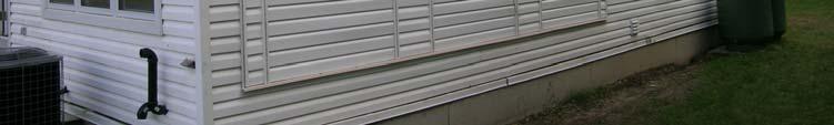


22 Rain Gauge
 9.2 10.0 RHT_1 (air) 7.")

23 LAYER 1 - Exterior Face of Vinyl Siding P_1 (High Pressure) RHT_1 (air) 7.0 T_20 (W2 only) LAYER 1 - Exterior Face of Vinyl Siding P_1 (High Pressure) RHT_1 (air) 7.0 T_20 (W2 only)
 10.0 4.0 DETEC_1 JW_1 RHT_3 13.0 15.0 DETEC_2 8.")

24 LAYER 2 - Exterior Face of Sheathing Membrane RHT_ P_2 (High Pressure) DETEC_1 JW_1 RHT_ DETEC_2 8.0 LAYER 3 - Exterior Face of OSB DETEC_ T_1 T_2 RHT_4 T_ DETEC_4 DETEC_ T_4 T_5 JW_2 RHT_ T_6 DETEC_6 6.0 DETEC_7 DETEC_8


25 LAYER 4 - Interior Face of OSB DETEC_9 T_7 RHT_6 T_ DETEC_10 DETEC_ MP_1 3.0 HF_1 (W2 only) T_9 RHT_7 JW_3 T_10 DETEC_12 DETEC Thermistor 2.0 DETEC_13 DETEC_14 LAYER 4 - Interior Face of OSB DETEC_9 T_7 RHT_6 T_ DETEC_10 DETEC_ MP_1 3.0 HF_1 (W2 only) T_9 RHT_7 JW_3 T_10 DETEC_12 DETEC Thermistor 2.0 DETEC_13 DETEC_14
 7.")

26 LAYER 5 - Stud Cavity 14.0 DETEC_15 DETEC_16 HF_2 (W2 only) 7.0 DETEC_17 MP_2 MP_3 LAYER 5 - Stud Cavity 14.0 DETEC_15 DETEC_16 HF_2 (W2 only) 7.0 DETEC_17 MP_2 MP_3

 10.0 15.")
")

27 LAYER 6 - Interior Face of Insulation & Stud Cavity (Exterior side of Vapour Barrier) T_11 RHT_8 T_ P_3 (Low Pressure) T_13 RHT_9 JW_4 T_14 HF_3 (W2 only) LAYER 6 - Interior Face of Insulation & Stud Cavity (Exterior side of Vapour Barrier) T_11 RHT_8 T_ P_3 (Low Pressure) T_13 RHT_9 JW_4 T_14 HF_3 (W2 only)
 Material Vinyl Siding Sheathing Membrane OSB Exterior Stud Cavity with Fiberglass Insulation Plastic Air/Vapour Barrier Drywall Interior Instrumentation -")
28 LAYER 7 - Interior Face of Drywall T_15 T_ T_17 RHT_10 (air) T_19 (W2 and W3 only) 7.0 T_ IRC Field Exposure of Wall Facility (FEWF) Material Vinyl Siding Sheathing Membrane OSB Exterior Stud Cavity with Fiberglass Insulation Plastic Air/Vapour Barrier Drywall Interior Instrumentation - Plan View RH and T sensors T sensors Air Pressure sensor Moisture Pins Jeld-Wen Wireless RH&T Sensors Heat Flux Transducer (for W2 only) DETEC


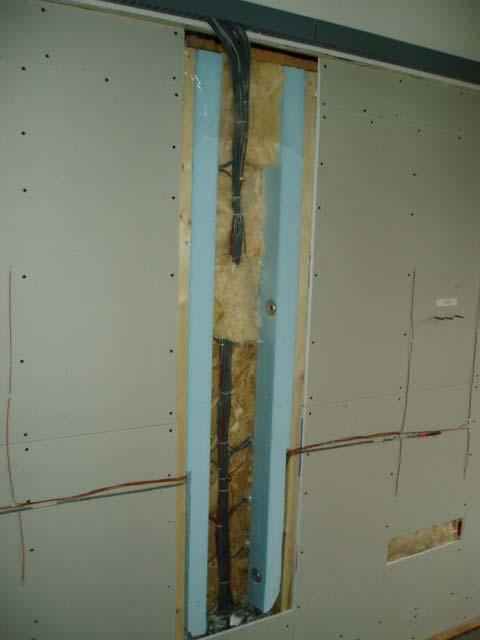
29 Around 17000ft of cable Ø View from interior of specimen. All dimensions in inches.

 9 x 8 zones inputs =")
30 RMU Board Layout -Rear Board Layout - Front 9 RMUs (Remote Monitoring Unit) 9 x 8 zones inputs = (72 zones)


31 9 Differential Pressure Transducers: 3 DP of 0.25 WC 6 DP of 2.5 WC


32 FEWF Instrumentation: Cable Wiring First Floor Basement Wall to Junction Boxes Trailer


33 10 RHT Sensors 3 DP Transducers 3 MP Sensors Junction Box Wall 2 3 HFT 1 RTD as Ref 20 Thermocouples FEWF Instrumentation: Cable Wiring First Floor Basement Wall to Junction Boxes Trailer
 through Fall, and part of the Winter under")

 Stage 2- Increase indoor RH to 45% and induce 10 Pa positive")
34 Experimental Approach The experiments will be in three phases: Phase 1: Commission the facility by monitoring three identical test specimens of traditional construction (2x6) through Fall, and part of the Winter under naturally occurring conditions. Phase 2: Challenging the wall during the Winter Stage 1- Create air leakage path and monitor under naturally occurring int. and ext. conditions on two of three specimens (1 week) Stage 2- Increase indoor RH to 45% and induce 10 Pa positive pressure while air leak path is present in two specimens, for 2 weeks (?) Phase 3: Return to naturally occurring conditions to monitor drying. Disassemble the indoor chamber

35 Experimental Approach The experiments will be in three phases: Phase 1: Commission the facility by monitoring three identical test specimens of traditional construction (2x6) through Fall, and part of the Winter under naturally occurring conditions. Phase 2: Challenging the wall during the Winter Stage 1- Create air leakage path and monitor under naturally occurring int. and ext. conditions on two of three specimens (1 week) Stage 2- Increase indoor RH to 45% and induce 10 Pa positive pressure while air leak path is present in two specimens, for 2 weeks (?) Phase 3: Return to naturally occurring conditions to monitor drying. Disassemble the indoor chamber
36 Experimental Approach The experiments will be in three phases: Phase 1: Commission the facility by monitoring three identical test specimens of traditional construction (2x6) through Fall, and part of the Winter under naturally occurring conditions. Phase 2: Challenging the wall during the Winter Stage 1- Create air leakage path and monitor under naturally occurring int. and ext. conditions on two of three specimens (1 week) Stage 2- Increase indoor RH to 45% and induce 10 Pa positive pressure while air leak path is present in two specimens, for 2 weeks (?) Phase 3: Return to naturally occurring conditions to monitor drying. Disassemble the indoor chamber Drywall


37 Air leakage path: a 6 mm crack in the polyethylene air barrier element as well as in the OSB panel


38 View from the outside OSB OSB OSB View from the outside

39 Air Leakage Path Experimental Approach The experiments will be in three phases: Phase 1: Commission the facility by monitoring three identical test specimens of traditional construction (2x6) through Fall, and part of the Winter under naturally occurring conditions. Phase 2: Challenging the wall during the Winter Stage 1- Create air leakage path and monitor under naturally occurring int. and ext. conditions on two of three specimens (1 week) Stage 2- Increase indoor RH to 45% and induce 10 Pa positive pressure while air leak path is present in two specimens, for 2 weeks (?) Phase 3: Return to naturally occurring conditions to monitor drying. Disassemble the indoor chamber

40 Drywall Conditioning Chamber on the Room Side

41 Wall specimen INT. EXT. Moisture-laden air exfiltration Conditioning chamber Experimental Approach The experiments will be in three phases: Phase 1: Commission the facility by monitoring three identical test specimens of traditional construction (2x6) through Fall, and part of the Winter under naturally occurring conditions. Phase 2: Challenging the wall during the Winter Stage 1- Create air leakage path and monitor under naturally occurring int. and ext. conditions on two of three specimens (1 week) Stage 2- Increase indoor RH to 45% and induce 10 Pa positive pressure while air leak path is present in two specimens, for 2 weeks (?) Phase 3: Return to naturally occurring conditions to monitor drying. Disassemble the indoor chamber
42 Outline Background Hygrothermal Performance of BES Modeling Field Experiments Laboratory experiments Concluding Remarks and Future Work Laboratory Experiments Why to do lab experiments? How to do experiment? Which physical phenomena to investigate,..? What do you expect from experiments?


43 Experiments Apparatus - EEEF Specimens and weighing apparatus are placed in EEEF EEEF maintains T and RH profile over course of experiment - 47 to 48 ± 1 ºC 10 to 100% RH ± 3% RH Environmental Exposure Envelope Facility Environmental Exposure Envelope Facility HOST COMPUTER 100 PSI - SHOP AIR AIR ACTUATED DIGITAL CONTROLLED SOLENOID VALVE Experiments Weighing System SERIAL LINK RS232 AIR OVER OIL CYLINDERS DOCO MICROCONTROLLER PNEUMATICS CONTROL MODULE HIGH SPEED SERIAL LINK PNEUMATIC CYLINDERS TENSION LOAD CELLS 2 HIGH RESOLUTION ACQUISITION MODULE 24 BIT A/D CONVERTER SIGNAL INPUT LC # 1 FILTERING INPUT LC # 2 TEST PANEL TO BE WEIGHED CONTROL & D/A SYSTEM SUPPORTING FRAME

44 Background Hygrothermal Performance of BES Modeling Field Experiments Laboratory experiments Concluding Remarks and Future Work Experiments Apparatus - EEEF
45 Concluding remarks FEWF is state-of-the-art field monitoring facility Field monitoring EEEF has demonstrated the capabilities of IRC s facilities to carry out a series of experimental works to mimic the exterior conditions effect on the moisture transport. Practice Review Numerical Modelling Lab Exp. Lab and/or Field Experiments help to benchmark models. Benchmarked models save time and money for doing parametric studies comparing to field and lab experiments Integrated Solutions for BE Industry Models, lab and field experiments complement each other Research House No. 3: Future Work HEATING AND VENTILATION FACILITY -IE FEWF- BES Field monitoring Practice Review Lab Exp. FY06/07 & 07/08 : Study & compare traditional & innovative HV strategies Numerical Modelling FY06/07 & 07/08: Study & compare traditional & innovative BE strategies
46 Research House No. 3: Future Work HEATING AND VENTILATION FACILITY FEWF Field monitoring Practice Review Lab Exp. FY06/07 & 07/08 : Study & compare traditional & innovative HV strategies IE B S Numerical Modelling FY06/07 & 07/08: Study & compare traditional & innovative BE strategies FY08/09: Cross- program project on interaction between BE and VIAQ Acknowledgments NRC for funding this cross program initiative between IRCs IE and BES programs IE/IAQ Group FEWF Team: William Lei Mike Nicholls Marianne Manning Roberts Berzins Stacey Nunes Khaled Abdulghani


47 Thank you Lab-EEEF Field-FEWF HAM Model-hygIRC 1D Dr. Wahid Maref Tel