Project Description. Projected build start date 03 May 2010 Projected date of occupation 06 Aug
|
|
|
- Amanda Small
- 5 years ago
- Views:
Transcription


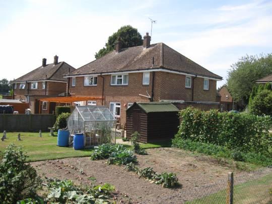
1 Project name Retrofit - Appledore, Ashford Project summary The key project approach is to develop a solution that uses complementary technologies and techniques, and primarily tackles the whole envelope through well insulating the walls, floors and roof, remedying air gaps and installing MVHR, thus reducing the initial heating load to 23 W/m2. A solar gain heat pump coupled with skirting board heating can then be installed to meet the vastly reduced heating and hot water. Finally, a PV system to offset the dwelling's electrical consumption will be installed. This should be done ideally with the residents remaining in situ. Figures in this database have been based on the no.13 property, heated by electric panels heaters and a log fire. Project Description Projected build start date 03 May 2010 Projected date of occupation 06 Aug 2010 Project stage Under construction Project location Appledore, Ashford, Kent, England Energy target Retrofit for the Future Build type Refurbishment Building sector Public Residential Page 1
2 Property type Semi-Detached Existing external wall construction Masonry Cavity Existing external wall additional information Cavity has been filled Existing party wall construction Uninsulated 250mm masonry cavity Floor area m² Floor area calculation method PHPP Project team Organisation Project lead Client Architect Mechanical & electrical consultant(s) Energy consultant(s) Structural engineer Quantity surveyor Other consultant Contractor Housing Services, Ashford Borough Council Giles Holloway Ashford Borough Council Housing Services B. Ball Contractors CEN Services Ltd B. Ball Contractors Design strategies Planned occupancy Space heating strategy Water heating strategy One property (A): Two elderly residents. To be compared to identical adjoining property (B) which houses a single parent family with four children. Application of a lightweight dual solar thermal and air source panel (solar gain heat pump system) with a low temperature flow skirting board heating system, will provide space heating and hot water to each of the dwellings. The technology will be backed up by an in-line immersion heater. Application of a lightweight dual solar thermal and air source panel (solar gain heat pump system) with a low temperature flow skirting board heating system, will provide space heating and hot water to each of the dwellings. The technology will be backed up by an in-line immersion heater. Fuel strategy Mains electricity. A will also require minimal columes of logs for their open fire. However, we would envisage that the frequency of use of the fire will be decreased greatly due to the increased comfort that the retrofit works will bring to their home. Page 2
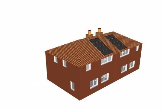
3 Renewable energy generation strategy Passive solar strategy Space cooling strategy Daylighting strategy Ventilation strategy A 1.2kWp PV photovoltaic panel array to be installed will be applied to each of the properties. All homes to have roof space of 15.36m2, within 45 degrees of south. Natural ventilation for most of the cooling season. Daytime use of MVHR with night purging during heat waves. Windows will be brought forward so that window reveals are not significantly increased. Mechanical ventilation with heat recovery (winter) Openable windows (summer) Airtightness strategy * Windows & doors replaced and sealed * Perimeter sealing of solid ground floor and upper floors Strategy for minimising thermal bridges * Continuous external wall insluation * Perimeter sealing of solid ground floor and upper floors * Replacement of window sills * Specialist installation of windows to prvent bridging Modelling strategy Insulation strategy Other relevant retrofit strategies Other information (constraints or opportunities influencing project design or outcomes) Whole house modelling was undertaken in PHPP, including each measure modelled seperately, as well as the final solution. * Application of external insulation to solid brick walls ( to achieve U-value of 0.14 W/m2K ); * Insulate solid floor ( to achieve U-value of 0.21 W/m2K) ; * Replacement of insulation in roof ( to achieve U-value of 0.10 W/m2K). We intend to carry out the major works within 5 days so that the tenants are only displaced for this amount of time and so that all works that may cause discomfort and inconvenience to the tenants are carried out while the property is empty. However, we have also demonstrated how this retrofit strategy can be undertaken with the residents in situ, insulating the floor on a room by room basis. The properties are located in an Area of Outstanding Natural Beauty. A brick coloured render system will therefore be applied to the external wall insulation. Alternatively, a brick clip affect could be applied to this solution. Energy use Fuel use by type (kwh/yr) Page 3
4 Fuel previous forecast measured Electri c Gas Oil 0 LPG Wood Primary energy requirement & CO2 emissions Annual CO2 emissions (kg CO2/m².yr) Primary energy requirement (kwh/m².yr) previous forecast measured Renewable energy (kwh/yr) Renewables technology forecast measured PV Energy consumed by generation Airtightness ( 50 Pascals ) Date of test Pre-development airtightness - Final airtightness - Space heat demand Test result Annual space heat demand ( kwh/m².yr ) Pre-development forecast measured Whole house energy calculation method Other energy calculation method Predicted heating load Other energy target(s) PHPP SAP modelling was also carried out 23 W/m² (demand) TOTAL PHPP Annual fuel costs: 338 TOTAL PHPP Annual CO2 emissions: 20kg/m2yr TOTAL PHPP Primary Energy: 100 kwh/m2yr Results for property no.14: Predicted Heating Load: 42 kwh/m² and yr Predicted Heating Load: 23 W/m² (demand) TOTAL PHPP Building services Occupancy Space heating Hot water Page 4
5 Ventilation Controls Cooking Lighting Appliances Renewables Strategy for minimising thermal bridges Building construction Storeys Volume Thermal fabric area Roof description Roof U-value Walls description Walls U-value Party walls description Party walls U-value Floor description Floor U-value Glazed doors description Glazed doors U-value Opaque doors description Opaque doors U-value Windows description Windows U-value Windows energy transmittance (G-value) Windows light transmittance Rooflights description Rooflights light transmittance Rooflights U-value Page 5

6 Project images Page 6
7 Page 7
8 Page 8