Feasibility Assessment Study
|
|
|
- Miranda Strickland
- 5 years ago
- Views:
Transcription


1 August 19, 2010 Feasibility Assessment Study Historic Sites Council Meeting

2 Today s Agenda Historic Overview Project Overview Barrier Issues Concrete Parapet Recommendations Steel Parapet Recommendations Deck Replacement Options Lighting Standard Questions
3 HISTORIC OVERVIEW


4 Historic Overview Listed on National Register of Historic Places Achieved ASCE Landmark Status The advisory Board to NJ Highway Commission approved a report on August 1923 that formed the general basis for the present Route 1&9 Corridor Exact locations and configurations of the Skyway were not finalized until 1929


5 Planning and Construction The Advisory Board outlined 5 points that defined the overall plan and construction approach: Use economical grades Elimination of drawbridges Elimination of curvature Additional Safety issues Elimination of grade crossings (street and railroad)

 Volume at the time was estimated at 5,500 vehicles")
6 Planning and Construction The proposed road was to be approximately 50 ft wide, sufficient to accommodate 5 traffic lanes (2 each direction, 1 10 ft for emergency use) Volume at the time was estimated at 5,500 vehicles per day


7 Planning and Construction Elimination of grade crossings forced the highway on structure Designers decided that the ramps should enter at the middle of the highway, which was widened and divided at these entry points The ramp system and its development is considered of historic significance, for it was one of the first attempts to create a coherent elevated highway network


8 Opening Day The Section of the Route 1 extension, called the Route 25 Connection Link, that comprises the majority of the current was officially opened on Thanksgiving Day, November 23, 1932


9 Historical Significance In 1932 the Route 1 Extension represented the single largest highway construction project undertaken in the US The Corridor was once described as the greatest highway project in the United States today It was also the first roadway project where public timesaving was used to justify dramatic capitol expenditures


10 Crash Rates Result in Changes Trucks were prohibited shortly after opening due to the high number of crashes Multi-car accidents were common due to lack of center barrier Within a year of opening, the newspapers and public christened the Skyway "Highway of Death

 Deck coated with silane surface treatment Concrete")
11 Changes After Opening Median barrier added in the 1950 s Based on 1978 Plans for Route US 1&9, Section 2AB & 5H: Existing deck resurfaced with latex modified concrete Aluminum safety shaped median added Safety improvements made Deck joints repaired Based on 1983 Plans for Route U.S. 1&9, Section 2AH & 5J: Encasement on steel members partially removed (Jersey City) Deck coated with silane surface treatment Concrete substructure repairs Structural steel repairs Bridge painted 2008 Deck Overlay Contract Deck repairs Sealing overlay applied Aluminum Safety Shaped Median

12 1998 Route 1 & 9 Corridor Preservation Plan Goals and Status Goal 1 Document Existing Corridor A. Photographically document existing structures according to HABS/HAER Standards - Haer Documentation completed for: 1. 12th St. Viaduct, and, 2. B. Review of Department files for suitable historic photographs and catalogue them Many of these have been transferred to the State Archives C. Catalogue original contract drawings - Since 9/11, Plans for current bridge structures cannot be made public Goal 2 Improve Physical Condition of Structures - What we are currently attempting A. Determine extent of improvements and potential impact on character defining features B. For actions in Preservation Plan, determine whether activity conforms to recommendations C. Where activity had significant impact on historic integrity, conduct alternatives analysis D. Where replacement or reconstruction required, minimize impact on historic integrity E. Implement improvements when funding becomes available to address structural deterioration

13 1998 Route 1 & 9 Corridor Preservation Plan Goals and Status Goal 3 Improve Traffic Safety Throughout the Corridor - What we are currently attempting A. Determine required safety improvements and potential impact on character defining features B. Where activity has significant impact on historic integrity, conduct alternatives analysis D. Where replacement or reconstruction required, minimize impact on historic integrity E. Implement improvements when funding becomes available to address safety upgrades Goal 5 Improve the Physical Appearance of the Corridor C. Provide lighting under Hoboken Ave Viaduct and on Skyway's through truss crossings of Rivers - Part of our current proposal and will use a lighting standard that simulates the original design

14 1998 Route 1 & 9 Corridor Preservation Plan Goals and Status Goal 6 Improve Public Awareness of the Corridor s Historic Significance A. Develop slide and or audio/visual program - We currently have a consultant under contract to develop a video script B. Develop traveling or permanent exhibition materials - NJDOT developed two exhibits that were on display commemorating the. - These were on display at the Newark and Jersey City Public Libraries last year. C. Prepare nomination documents for designation as an ASCE Landmark - The has been designated a Landmark by the American Society of Civil Engineers

15 1998 Route 1 & 9 Corridor Preservation Plan Contributing Historic Elements Profile and viaduct construction Center access ramps Railings and Parapets Concrete encasement

16 Preservation Options General Guidance Structural Systems Removing, changing, covering structural elements not recommended Proper maintenance essential Repairs by augmenting or upgrading individual parts/features Replace in kind recommended. Substitute materials must convey same form, design and overall appearance Safety Concerns Need for safe structure that meets code Investigate alternatives that minimize or reduce damage to character defining features Design exceptions may be warranted

17 Preservation Options General Guidance Modifications/Additions Goal of continued use will necessitate modifications/additions, including roadway widening, ramp modifications, etc. Ensure minimal loss/removal of character defining features (i.e. concrete Parapets) Same size/scale as existing features Do not duplicate exact form with reproductions, but maintain compatibility with historic structure Make clear visual distinction between old and new
 to match original concrete color Where partial removal")
18 Preservation Plan Specific Elements Concrete Encasement Rehabilitate encasement in stable condition to not impact load carrying ability Remove encasement where: Necessary to increase load carrying capacity Public safety at risk due to falling concrete Badly deteriorated or unstable concrete Where removed, apply protective coating (paint) to match original concrete color Where partial removal justified, remove all encasement to maintain consistent look

19 Parapets/Railings Rehab/reuse existing Parapets/railing that are not a safety issue Use supplemental interior railing/modify safetywalk to maintain external visual appearance Remove badly deteriorated railings/parapets if not economically feasible to rehab use form liners suggestive of original for concrete railings Where replacement necessary, use railings suggestive of original Concrete Deck Slabs Preservation Plan Specific Elements Deck slab not technologically significant Deck slab not character defining element Rehab structurally sound decks Reconstruct inadequate decks Consider lighter decks/composite action to allow reuse of supporting members


20 PROJECT OVERVIEW

21 Project Purpose and Need Bring the into a state of good repair and address the structural deficiencies, mitigate to the degree practical the functional deficiencies, and improve the overall condition and safety of the roadway. Project Goals: Maintain Skyway as a vital transportation linkage serving a large market base including trans-hudson trips Bring Skyway into State of Good Repair and address functional and operational issues to the degree practical Extend useful life of Skyway Improve safety for motorists on Skyway


22 Project Limits Newark Ramp Kearny Ramp Tonnele Ave Circle NEWARK KEARNY Broadway Ramp EB/WB Tonnele Ave Ramps JERSEY CITY Project Limits and Access Points to the Skyway

23 Skyway is 18,480 Feet Long 118 spans on structure ft. through truss main spans & 350 ft. flanking spans over Passaic & Hackensack Rivers 3 steel through trusses over railroad in Jersey City Superstructure constructed in 12 main construction sections deck was separate contract Original concrete deck slab still remains

24 Overall Condition: Poor Components: Deck: Superstructure: Substructure: Poor Poor Fair Structurally Deficient Poor ratings Structural steel defects Functionally Obsolete Poor geometrics Low vertical clearances Sufficiency Rating = 2 out of 100

25 Interim Repair Contracts Series of interim projects implemented No. 1 - Deck repairs Spans A0 to 44 Complete - $23M No. 2 - Deck repairs Spans 45 to overlay entire deck Completion pending resolution of construction issues - $23M No 3. - Priority repairs from inspection report Complete - $6M No 4. Drainage protection repairs Ongoing - $38M To date NJDOT has spend $90M in repairs to Skyway

26 Necessary Repairs Deck slab needs replacement Type depends on need for overnight construction Will use closed drainage system (prevents structural steel damage Railings /Parapets are substandard/untested Many steel components deteriorated Still evaluating existing gusset plates/rivets for capacity Safety concerns at interior ramp entrances Overall safety of roadway/width Substructure needs repairs
27 PARAPET ISSUES

28 Parapet Study Report Decision on railing needs to be made in conjunction with the following interconnected issues: Historical considerations Deck replacement Drainage and open curbs Safety walks/railings Historical/period light standards Structural complications/fascia girder Constructability/time constraints

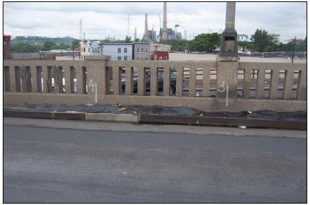
29 Existing Parapet Type Steel Steel Steel Solid Concrete Pipe Concrete Fence
 Discontinuity (due to open joints) Suspect crash worthiness (structural and functional adequacy) of the existing railing")
30 Deficiencies Vaulting potential Snagging features (bridge rail does not have smooth continuous traffic face and posts or pilasters extend more than 2 inches from the rail surface) Discontinuity (due to open joints) Suspect crash worthiness (structural and functional adequacy) of the existing railing systems

 Span")
31 Existing Parapet Condition Span 20 (South bridge guiderail) Span 42 NB


32 Existing Parapet Condition Span 104 south bridge railing near Pier 104 (Northbound Roadway) Span B South Railing (Newark Ramp)

33 Existing Steel Parapet MAINLINE

34 Existing Pipe Steel Railing Pipe Railing KEARNY RAMP
35 CONCRETE PARAPET RECOMMENDATIONS

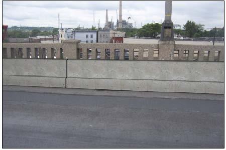
36 Existing Concrete Parapet Spans from the Northern terminus to Pier 44 Majority of the railing is an open or See-Through aesthetic concrete Parapet Approximately 2,800 feet long (per fascia)
37 Existing Concrete Parapet ELEVATION VIEW

38 Existing Concrete Parapet Repairs

39 Key Design Elements Comply with historic appearance of original parapet Meet TL-4 design criteria Conventional drainage system to be maintained
 Main Advantages Ease of construction Simple detailing Reduced impact")
40 Proposed Concrete Parapet IOWA BARRIER CONCRETE BLOCK RETROFIT Reconstruct original open or See- Through aesthetic concrete Parapet Provides a crash tested rigid concrete barrier inboard of aesthetic concrete Parapet Meets second preferred preservation option ( Use supplemental internal railing to maintain external appearance ) Main Advantages Ease of construction Simple detailing Reduced impact to historic appearance of the structure Disadvantage Loss of safetywalk
41 STEEL PARAPET RECOMMENDATIONS

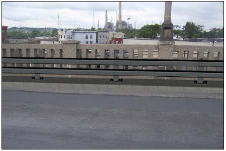
42 Existing Steel Parapet Spans from Pier 44 to the Southern terminus Heavy built-up steel railing Approximately 15,430 feet long (per fascia)
43 Existing Steel Parapet ELEVATION VIEW
 Parapet options impacted by type of MPT provided (overnight construction vs.")
44 Key Design Elements Comply with historic appearance of original Parapet Meet TL-4 design criteria Conventional drainage system to be provided (closed curb system with scuppers) Parapet options impacted by type of MPT provided (overnight construction vs. conventional construction) Parapet interconnected with fascia
 Main advantages Ease of construction Simple detailing Reduced impact to historic appearance of the")
45 Proposed Steel Parapet IOWA BARRIER CONCRETE BLOCK RETROFIT Retains original historical steel railing Provides a crash tested rigid concrete barrier inboard of the existing railing Meets second preferred preservation option ( Use supplemental internal railing to maintain external appearance ) Main advantages Ease of construction Simple detailing Reduced impact to historic appearance of the structure Disadvantage Loss of safetywalk

46 Sample of Iowa Block Rail IOWA BARRIER CONCRETE BLOCK RETROFIT

47 Proposed Barrier Alternatives

48 Proposed Barrier Alternatives

49 DECK REPLACEMENT OPTIONS

50 Maintenance and Protection of Traffic (MPT) during Deck Rehab Central MPT Issue: Maintain traffic lanes at all peak times or close lanes to speed construction Maintaining 4 lanes in peak periods increases construction duration and cost Requires overnight construction Requires precast deck systems for deck replacement Closing one side of bridge speeds construction & reduces costs Maintain one lane in each direction Conventional CIP decks can be used Contractor has free reign to work around the clock Results in added delays during peak periods Impacts of delays to the public need to be considered
 Provides long term benefit to the project to address safety")
51 Widening Potential Potential to widen up to 8 feet in non-thru truss areas Impacts Maintenance and Protection of Traffic (MPT) considerations Allows contractor to maintain all 4 traffic lanes during construction except in the first stage Provides increase in safety by providing 8 shoulder for breakdown lane (does not add a travel lane) Provides long term benefit to the project to address safety and operational issues Improves maintenance access
52 Potential Widening Options

53 Widening Options No Widening Widening

54 Deck Replacement Options Under Review Assessing traffic impacts of bound or lane closures Assessing construction and user costs
55 LIGHTING STANDARD

56 Original Light Fixture

57 Proposed Light Fixture Replicates Period Lighting Approved by SHPO


58 Next Steps Feasibility Assessment still underway Completion of steel strength testing Alternative selection Draft Feasibility Assessment report


59 Questions Address any questions to: David Mudge Phone: