Addendum # 2. T Title: JD Kline Water Supply Plant Roof Replacement
|
|
|
- Lee McCoy
- 5 years ago
- Views:
Transcription

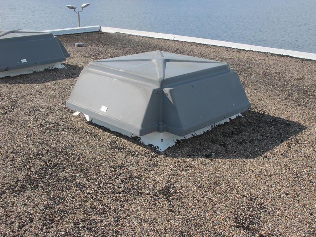
1 Date: May 16 th, 2017 Addendum # 2 T Title: JD Kline Water Supply Plant Roof Replacement To All Bidders of T : Please note: the following addendum applies to T and shall be taken into consideration when preparing bid documents. In Section Item 10.2 Project Documents, add attached sketch ASK-05 to the drawing list under the JD Kline Water Supply Plant Roof Replacement. In Section Item 2.2 Polyisocyanurate Insulation Add Tapered insulation at 1% slope is to be used on Roof A with a thickness of 2 at 2 feet from the drain. Add In order to reduce ponding on Roof B, along line T, tapered insulation at a slope of 2% is to be added to the 2 insulation already specified for a width of 12 feet and running from line 25 to line 33. On Reference Drawing A-1 Water Treatment Plant Roof Add Note 7 Install 4 ½ of additional blocking to the skylight curb to accommodate the tapered insulation. The following pictures from the JD Kline Water Supply Plant Pumping Station roof are provided as information to bidders. Brent Hickman, S.C.M.P., Procurement Officer Halifax Water Tel: (902) Fax: (902) procurement@halifaxwater.ca

2
3 A signed copy of each Addendum must also be included with the bid submission. Failure to include this Addendum may be cause for rejection. If you have any questions, please contact our office by at ALL OTHER SPECIFICATIONS, TERMS AND CONDITIONS REMAIN UNCHANGED. Acknowledgement by Bidder: Company Name: Print Name: Signed: Date: End of Addendum #2
4
5 Date: May 8 th, 2017 Addendum #1 T Title: JD Kline Water Supply Plant Roof Replacement To All Bidders of T : Please note: the following addendum applies to T and shall be taken into consideration when preparing bid documents. Response to questions received: Question 1: Will a streets and services permit be required for this project as per section , 3.9? Answer 1: A streets and services permit will not be required for this project. Question 2: Section , 12. Insurance references section for insurance requirements. Section is missing from the documents issued for tender. Please advise. Answer 2: Section Item 12 is referring to the section included in the 2017 Standard Specification for Municipal Services. All tenderers are encouraged to obtain a copy of the document via information outlined in section Overview. Question 3: Two copies of specification section PS were issued with the tender documents. This section is for the Pumphouse roof. Please advise if we are to use this specification for Roof Areas A, B & B1 as well. Answer 3: Replace one of the duplicate sections PS with the attached section (Pockwock Water Treatment Plant Roof Phase 1). The scope of work for this project includes the replacement of the pumping station roof and the phase outlined for the replacement on the treatment plant roof. A signed copy of each Addendum must also be included with the bid submission. Failure to include this Addendum may be cause for rejection. If you have any questions, please contact our office by at procurement@halifaxwater.ca. Brent Hickman, S.C.M.P., Procurement Officer Halifax Water Tel: (902) Fax: (902) procurement@halifaxwater.ca
6 ALL OTHER SPECIFICATIONS, TERMS AND CONDITIONS REMAIN UNCHANGED. Acknowledgement by Bidder: Company Name: Print Name: Signed: Date: End of Addendum #1
7 T Page 1 PART 1 - GENERAL 1.1 SCOPE OF THE WORK.1 The project has been divided into three phases:.1 PHASE 1:.1 Is made up of Roof Block A and B where the existing roofing is to be removed down to existing concrete and the surface power broomed with a machine fitted with steel brushes..2 The new roof is made up of a new torched mod bit vapour barrier, 2" polyisocyanurate insulation, insulation cover board with factory applied base sheet and torched mod bit cap sheet. All layers are adhered together with two part low rise adhesive in the edge width and field and mechanically secured in the corners..3 PHASE 1 is to be done in the summer of PHASES 2 and 3: Roof Block C, D, E and F will be done at some future date. 1.2 RELATED WORK PERFORMED BY OTHERS.1 The owner has awarded contracts to two mechanical contractors to remove two AHU=s, install one HRV, install one new fan and one new gooseneck vent, one new service box and replace one chimney..2 All mechanical modifications are to be completed before the roofer for this contract starts work. The two mechanical contractors have been issued ASK drawings which detail how they are to complete new curbs and remove and blank off old services. As information for the roofer of this contract the details for the modifications listed in are shown on drawing A RELATED WORK PERFORMED BY OWNER.1 The owner will have the have the communications antenna on Roof B-1 removed and reinstalled once the raised curb is completed..2 The owner will have the duct from the gooseneck vent on Roof B-1 extended. 1.4 REFERENCES.1 CSA B Tapping and Drive Screws (Slotted and Recessed Head, Thread)..2 CGSB 37-GP-56M-80 Membrane, Modified, Bituminous, Prefabricated, and Reinforced for Roofing..3 Canadian Roofing Contractors Association - CRCA Roofing Specifications Manual - latest edition..4 CAN/ULC-S704 Thermal Insulation, Polyisocyanurate Boards and Pipe Covering..5 CSA A , Dynamic Uplift Resistance Test.
8 T Page SHOP DRAWINGS.1 Provide product data for each component / material to be provided. 1.6 STORAGE AND HANDLING.1 Provide and maintain dry, off-ground weatherproof storage..2 Store rolls of membrane in upright position..3 Remove only in quantities required for same day use..4 Place plywood runways over work to enable movement of material and other traffic..5 Store caulking at +5ΕC minimum..6 Store insulation protected from weather and deleterious materials. 1.7 PROTECTION.1 Fire Extinguishers: maintain one stored pressure rechargeable type with hose and shut off nozzle, ULC labeled for A, B, and C class protection. One size 9 kg unit on the roof per torch applicator, within 6 m of the applicator..2 Maintain fire watch for 1 hour after each day=s roofing operations cease. 1.8 ENVIRONMENTAL REQUIREMENTS.1 Do not install roofing when wind chill temperature remains below -18 degrees C for torch application..2 Install roofing on dry deck, free of snow and ice, use only dry materials and apply only during weather that will not introduce moisture into roofing system. 1.9 WARRANTY.1 Contractor hereby warrants that modified bituminous roofing and membrane flashings as follows:.1 2 year CRCA materials and workmanship against leaks and blow off year material warranty that the membrane will perform as a roofing material..2 1 year CRCA warranty against defects of materials and workmanship for the sheet metal work COMPATIBILITY.1 Compatibility between components of roofing system is essential. Provide written declaration to Architect stating that materials and components, as assembled in system, meet this requirement.
9 T Page 3 PART 2 - PRODUCTS 2.1 VAPOUR BARRIER.1 Vapour Barrier: to CGSB 37-GP-56M, Styrene-Butadiene-Styrene (SBS) elastomeric polymer, prefabricated sheet, polyester reinforcement, weighing 180 g/m2..1 Type 2, fully adhered..2 Class C-plain surfaced..3 Grade 2 heavy duty service..4 Top and bottom surfaces:.1 Sanded / Polyethylene.5 Acceptable material:.1 Modiflex MP FS Base by IKO.2 Sopralene 180 SP by Soprema 2.2 POLYISOCYANURATE INSULATION.1 Polyisocyanurate insulation: to ULC-CAN-S701.2 Type 2, Class 3..3 Size 4' x 4' square edge..4 Sump insulation by 1" at drains..6 Acceptable material;.1 Sopra-ISO by Soprema.2 IKO Therm 2.3 TWO PART LOW RISE FOAM ADHESIVE.1 Two part low rise polyurethane adhesive for roofing insulation and overlay boards..1 Acceptable material:.1 IKO Millennium.2 Soprema Duotack 2.4 FASTENERS.1 #12 FM approved screws for wood blocking..2 #14 FM approved screws, purpose made, use in a concrete deck. Used for securing roof cover board in corner areas into pre drilled holes in concrete deck. 10 threads per inch. Acceptable material:.1 Heavy Duty Roofing Fastener by Olympic Fasteners Roofing Products. 2.5 INSULATION COVER BOARD WITH FACTORY APPLIED BASE SHEET.1 Support panel composed of 180 gram base sheet with therofusible surface laminated to ISO high density recovery board. Total thickness approximately 1/2"..2 Acceptable material:.1 Soprasmart - ISO HD 180 by Soprema.2 ShieldBase 180 by IKO
10 T Page CAP SHEET MEMBRANE.1 Cap sheet: to CGSB 37-GP-56M, Styrene-Butadiene-Styrene (SBS) elastomeric polymer prefabricated sheet, polyester reinforcement, weighing 250 g/m2..1 Type 1, fully adhered..2 Class A-granule surfaced..3 Grade 2 heavy duty service..4 Bottom surface polyethylene.5 Acceptable material:.1 PrevENT TP 250 Cap by IKO.2 Sopralene Flam 250 FR GR by Soprema 2.7 SEALERS AND PRIMER.1 Modified plastic cement: asphalt, to CAN/CGSB Sealing compound: to CAN/CGSB037.29, rubber asphalt type..3 Primer for modified roof membrane as recommended by the membrane manufacturer. 2.8 METAL FLASHING.1 22 gauge pre-painted steel - Colorite HMP finish..2 Color - to match existing. 2.9 ROOF DRAINS.1 Reuse existing 2.10 PLYWOOD AND WOOD.1 Wood for blocking to be No. 1 or better S-P-F NOT PRESSURE TREATED..2 Plywood to be softwood plywood - select PLUMBING VENT FLASHING.1 Thaler Stackjack Flashing SJ-37-7" high, insulated SPLIT FLASHINGS.1 Thaler SPJ-1 split flashings for duct work support legs EXPANSION JOINT.1 Situra FlamLINE CHEMLINK SEAL.1 ChemCurb / E Curb System consisting of:.1 Precast polyester shell.2 M-1 Structural Adhesive / sealant.3 1-Part self levelling pourable sealant
11 T Page 5 PART 3 - EXECUTION 3.1 WORKMANSHIP.1 Do roofing work in accordance with applicable, standard in Canadian Roofing Contractors Association (CRCA) Roofing Specifications Manual, latest edition, and the printed instructions from the membrane manufacturer. 3.2 REMOVALS PHASE 1.1 Remove expansion joint flashing and dispose of legally off site..2 Remove the existing roof system to the level of the existing two ply felt and asphalt vapour barrier. Remove all felt and asphalt vapour barrier which is not well adhered. Power broom the surface with a machine fitted with wire brushes to ensure that remaining membrane is well adhered. Use hand held grinders with cup wire brushes to remove material in areas where the power broom can not reach. Dispose of all debris legally off site..3 Remove the infill roofing done earlier by the roofers working for the mechanical contractors..4 Remove the existing skylight and save for re-installation 3.3 PROTECTION.1 Cover walls and adjacent work where materials are hoisted or used..2 Use warning signs and barriers. Maintain in good order until completion of work..3 Clean off drips and smears of bituminous material immediately..4 Ensure that all roof drains remain in operation from the start of the project until completion. Temporarily lower drains to the level of the new vapour barrier as strip off occurs and raise as re-roofing proceeds. Clamping rings are to be re-installed at the end of every day. Temporary drains must be secured with MJ coupling so a blocked drain line can not back up and drain into the building. Use unequal diameter MJ couplings where required to make these connections..5 Protect roof from traffic and damage. Comply with precautions deemed necessary by Architect..6 At end of each day's work or when stoppage occurs due to inclement weather, provide protection for completed work and materials out of storage. 3.4 EXAMINATION ROOF DECKS.1 Strip existing roofing off to bare concrete deck and dispose of all material legally off site. Existing vapour barrier which is well adhered can remain. Power broom the surface to ensure good adhesion of remaining felt and asphalt..2 Examine roof decks and immediately inform the Architect in writing of any defects.
12 T Page INSTALLATION OF VAPOUR BARRIER ON PERIMETER CURBS.1 To ensure that membrane is not torched direct to wood a dry 180 base sheet is to be installed over the wood at existing perimeter curbs and nailed at 4" c/c each way..2 Torch specified base sheet solid to the nailed base sheet at perimeter curbs with edge and end laps as specified by the manufacturer. 3.6 DECK PRIMING.1 Prime the deck with primer recommended by the roof membrane manufacturer and let primer dry completely. 3.7 INSTALLATION OF VAPOUR BARRIER ON CONCRETE DECK.1 Torch specified base sheet membrane to primed concrete deck with edge and end laps as specified by the membrane manufacture to provide a vapour barrier and temporary roof. Heat weld all laps at the end of every day..2 Carry vapour barrier up the concrete curb face and extend to the outside of the concrete curb. 3.8 INSTALLATION OF INSULATION IN FIELD AND EDGE WIDTH.1 Install insulation with 1/2" width ribbons of specified two part low rise adhesive. The 1/2" ribbon width is to be measured immediately upon exiting from the nozzle..2 Density of beads to be 12" c/c in the field and 6" c/c in the edge width and corner. Edge width is 12 feet. See drawing..4 Set the roof insulation immediately into the fresh adhesive before it has started to shin over..5 Immediately after setting the insulation in the adhesive weight down each block of insulation with four 5 gallon buckets of ballast until the adhesive has achieved a full set. 3.9 INSTALLATION OF INSULATION COVER BOARD IN FIELD AND EDGE WIDTH.1 Install insulation cover board with joints staggered from those in the insulation layer and all edges tightly butted using the same adhesive bead size and pattern as for insulation.2 Ballast down each board with sufficient buckets of temporary ballast to ensure good contact before adhesive sets up..3 Heat weld all end and side laps.
13 T Page INSTALLATION OF INSULATION AND INSULATION COVER BOARD IN CORNER.1 In corners mechanically secure the base sheet with screws and plates into pre drilled holes in the concrete. Fastener density to be as per CSA A 123.2:.1 IKO design PUB-DRU rows at 35" c/c and fasteners at 6" c/c..2 Soprema design PUB-DRC rows at 24" c/c and fastener spacing at 12" c/c as per SOP EXPOSED MEMBRANE APPLICATION.1 Base sheet flashing application:.1 Complete installation of flashing base sheet stripping prior to installing membrane cap sheet..2 Torch base and cap sheet onto substrate in 1 meter wide strips..3 Lap flashing base sheet to membrane base sheet minimum 150 mm and seal by torch welding..4 Lap flashing cap sheet to membrane cap sheet 250 mm minimum and torch weld..5 Provide 75 mm minimum side lap and seal..6 Properly secure flashings to their support, without sags, blisters, fish mouths or wrinkles..7 Do work in accordance with manufacturer's recommendations..2 Cap sheet application:.1 Starting at low point on roof, perpendicular to slope, unroll cap sheet, align and re-roll from both ends..2 Unroll and torch cap sheet onto base sheet taking care not to burn membrane or its reinforcement..3 Lap sheets 75 mm minimum for side laps and 150 mm minimum for end laps. Offset joints in cap sheet 300 mm minimum from those in base sheet..4 Application to be free of blisters, fishmouths and wrinkles..5 Do membrane application in accordance with manufacturer's recommendations..3 Self-adhesive membrane flashing application:.1 Prime the exterior wood surface of the roof edge blocking and install self-adhesive membrane over the full surface. Lap modified bituminous flashing membrane down over the self-adhesive membrane without torching and nail with roofing nails at 6" c/c along the edge of the membrane CHEMLINK SEAL INSTALLATION.1 Install the ChemCurb / E Curb System as per the printed instructions of the manufacturer..2 Remove all previous caulk, mastic cement, asphalt and other contaminants from the cables with a wire brush to ensure proper bonding..3 Ensure that there is a minimum of 1" spacing between each of the cables and a 1' space from cables to the edge of the shell.
14 T Page METAL FLASHING.1 Install as detailed using CRCA approved metal fabrication methods CLEANING.1 Remove bituminous markings from finished surfaces..2 In areas where finished surfaces are soiled by work of this section. Consult manufacturer of surfaces for cleaning advice and comply with their documented instructions..3 Repair or replace defaced or disfigured finishes caused by work of this section FIELD QUALITY CONTROL.1 Periodic site review of roofing application will be carried out by the Architect. END OF SECTION