GEOTECHNICAL ENGINEERING CHALLENGES ON SOFT GROUND. For Myanmar Engineering Society 2012 CONTENTS
|
|
|
- Luke Nichols
- 5 years ago
- Views:
Transcription
 CONTENTS 1. Introduction 2. Identity of Soft Ground 3. Soft Ground in South East Asia 4. Embankment Failures 5. Failure of Bridges Approaches 6. Settlement of Culvert and Bridge Approaches 7.")
1 GEOTECHNICAL ENGINEERING CHALLENGES ON SOFT GROUND For Myanmar Engineering Society 2012 G&P Professional Sdn Bhd ( By Engr. Dr. Gue See Sew (P.Eng) Engr. Dr. Wong Shiao Yun (G.Eng) CONTENTS 1. Introduction 2. Identity of Soft Ground 3. Soft Ground in South East Asia 4. Embankment Failures 5. Failure of Bridges Approaches 6. Settlement of Culvert and Bridge Approaches 7. Building Failures 8. Excavation Failures 9. Some Solutions to the Problems on Settlements Bridge Approaches Culvert Approachs 10. Guidance Notes on Subsoil Investigation 11. Conclusions 1


2 CHALLENGES FOR GEOTECHNICAL ENGINEERS ON SOFT GROUND Consolidation Settlement Bearing Capacity and Consolidation Settlement FAILURE SABAH 2

3 FAILURE SIBU FAILURE 3


4 FAILURE FAILURE EVENT IN SINGAPORE 4
5 FAILURE EVENT IN OKLAHOMA, USA FAILURE EVENT IN CHINA 13 Storey Apartment Collapsed in China 5

6 IDENTITY OF SOFT GROUND VEGETATION 6

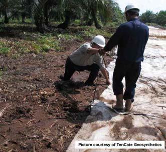
7 VEGETATION IDENTITY OF SOFT GROUND 7


8 IDENTITY OF SOFT GROUND S u > 10kPa S u < 10kPa IDENTITY OF SOFT GROUND 8

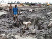
9 SOFT CLAY / PADDY FIELD MIX-DEVELOPMENT 9


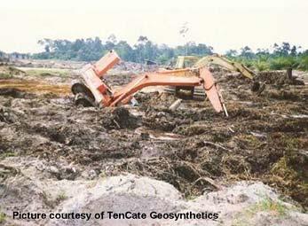
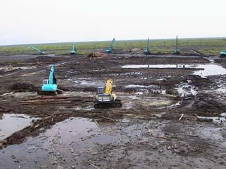
10 How Soft? Click to play How Soft? 10


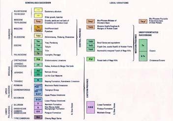
11 Soft Ground in South East Asian Alluvial Deposits Yangon Alluvium 11
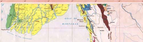
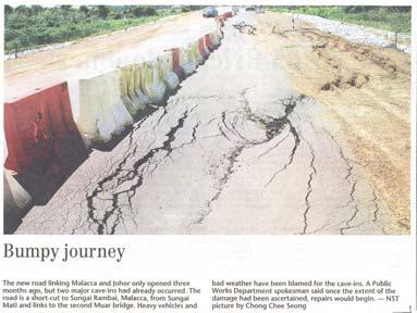
12 Yangon EMBANKMENT FAILURES 12
13 Embankment Treated with Vacuum Preloading with Vertical Drains Embankment Fill (Without Vacuum Preloading) Embankment Fill (Failed Area) (Vacuum Preloading with Vertical Drains) Liner and Sand Layer for Vacuum System Very Soft Silty CLAY Vertical Drains Soft Sandy CLAY Very Loose Clayey SAND Medium to Stiff Silty CLAY and Clayey SILT Scale (m) (After Gue et al. 2001) Embankment Failure Embankment failed = Fill height of 5.5m After Failure of Vacuum Preloading Remedial with Stone Columns. Embankment Failed Again at 3.2m Heave Up Sheer Drop and Cracks 13
14 Undrained Shear Strength Profile Undrained Shear Strength, Su (kpa) Sensitivity, St Su = 10 kpa 2 Su = 8 kpa Depth (m) Su = 13 kpa Su = 17 kpa Su = 19 kpa Su-Undisturbed from VS-A Su-Remolded from VS-A Su-Undisturbed from VS-B Su-Remolded from VS-B In-Situ Vane Shear Test VS-A VS-B Monitored Pore Water Pressures Fill Height (m ) Stage E Stage D Stage C Stage B Stage F Fist Crack Observed on Day Days Piezometer Head (m) Designed Water Head is 8m at PZ-A3 Designed Water Head is 6m at PZ-A2. Designed Water Head is 3m at PZ-A1 Excess Pore Water Pressure generated at PZ-A3, Δ U = + ve Excess Pore Water Pressure generated at PZ-A2, Δ U = + ve Piezometers at Location A at 3.0m depth at 6.0m depth at 8.0m depth 14

 15")
15 Failure of Embankment treated with Stone Columns Only Priebe s Method was used Bulging & General Shear Failures not checked Independent review shows inadequate General Shear Capacity Methods of Estimating Ultimate Bearing Capacity Large range of possible Ultimate Bearing Capacity Attention when using stone columns in very soft ground (e.g. su < 15kPa) 15
16 Lessons Learned Vacuum Preloading Method shall be closely monitored Remedial design for failed embankment shall used disturbed soil strength Stone columns design shall check for all modes of failure + Observational Method (recommended) Understand the Limitation of Software used It may not check all the required modes of failures Stone Column 16
17 Stone Column The Principle Stone Columns = Granular Pile = Vibro Replacement Involves partial replacement of unsuitable subsoil with compacted column of stones or aggregates Sand platform Soft clay Stone column Firm strata D Usually completely penetrates the weak strata FAILURE OF BRIDGE FOUNDATIONS AND APPROACH EMBANKMENT 17

18 Overview Abutment I Abutment II Pier I Pier II Overview Abutment I Abutment II Pier I Pier II 18

19 Subsoil Condition 20m coastal & alluvium CLAY Sheer Drop Sheer Drop Pilecaps 19


20 Slip Failure Tilted Abutment & Gap between Bridge Decks Tilt from Vertical Opening between bridge 20

21 Pier II Tilted Pilecap Slip Failure of Embankment At 25m behind Abutment II Abutment II : - Tilted 550mm on top - Angular distortion of 1/6 300mm gap between bridge decks 21
22 Geotechnical Investigation H 3m H 5.5m NOT SAFE HOW TO CHECK? What Is The Critical Height? H failure = (N( c x Su) / γ fill N c 5 H failure = (5 x Su) / γ fill e.g. : When Su = 10 kpa ; γ fill = 18 kn/m 3 H failure = (5 x 10)/ 18 = 2.8 m 22
23 Lessons Learned Failures (temporary works) - Inadequate geotechnical design - Subsoil Condition (Lack of understanding) - Lack of construction control & supervision Preventive Measures Proper design and review Stability check of embankment & abutment Most critical :- During construction (must check temporary works) Proper full-time supervision (with relevant experience & understand design assumptions) 23

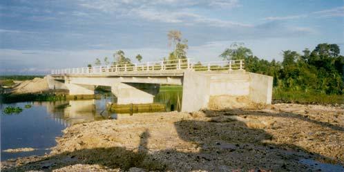
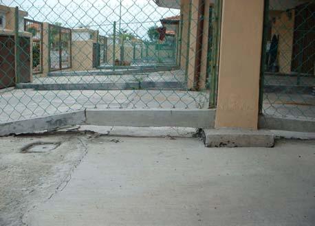
24 SETTLEMENT OF APPROACHES TO CULVERTS 24
25 Final Profile O.G.L. Long Term Profile Pile PILED CULVERT SETTLEMENT OF APPROACHES TO BRIDGES 25


26 Undulating Mushroom and undulating surface Differential Settlement 26

27 Typical Cross-Section Final Profile Abutment O.G.L. Long Term Profile Pile 27


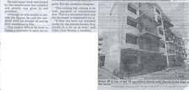
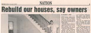
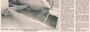
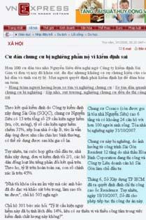
28 BUILDING FAILURES Newspaper clippings 28
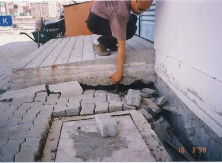
29 Settlement Settlement 29
30 Conventional Foundation for Low Rise Buildings Conventional Foundation for Low Rise Buildings (Soil Settlement) 30


31 Settlement Exposed Pile Comparison Building on Piles Building on Piled Strips Fill 25-30m Soft Clay Strip System Stiff Stratum Hard Layer 31


32 Comparison (after settlement) Building on Piles Building on Piled Strips Fill 25-30m Soft Clay Strip System Stiff Stratum Hard Layer Ho Chi Minh City 32


33 Leaning Tower of Italy Consolidation settlement for > 800 years PISA TOWER J. B. Burland (1998) 33
34 Settlement (m) Inclination ( ) Date Relationship between time, inclination and settlement simulation of the history of the Pisa Tower (Extracted from The Enigma of The Leaning Tower of PISA by John B. Burland 1998) EXCAVATION FAILURES 34
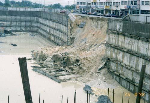
35 35
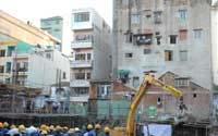
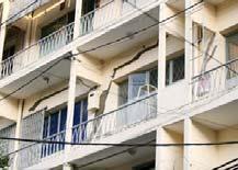
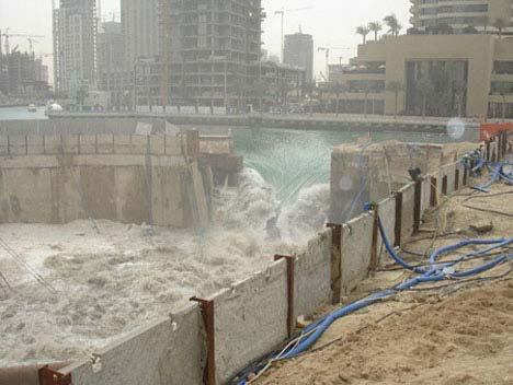
36 EXCAVATION FAILURES FAILURE EVENT IN VIETNAM 36


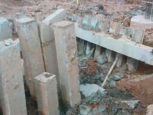
37 13 Storey Apartment Collapsed in China 13 Storey Apartment Collapsed in China First, the apartment building was constructed Then the plan called for an underground garage to be dug out. The excavated soil was piled up on the other side of the building. 37


38 13 Storey Apartment Collapsed in China Heavy rains resulted in water seeping into the ground The building began to tilt Then it began to shift and the "hollow" concrete pilings were snapped due to the uneven lateral pressures. 13 Storey Apartment Collapsed in China 38
39 SOME SOLUTIONS ON SETTLEMENT SURCHARGING WITH OR WITHOUT PVD 39
40 Surcharging Temporarily compress the subsoil with higher pressure than permanent load Achieve higher initial rate of settlement + reduce long term settlement Larger portion of fill left behind If fill material is available Surcharging Finished Level Surcharge Embankment Soft Soil 40
41 Surcharging Fill Thickness Filling Rest Period With Surcharge Without Surcharge Time t 2 t 1 Time FASTER Settlement Without Surcharge With Surcharge Construction Surcharge Duration Service Life of Embankment Vertical Pressure from Embankment Loading Service Life of embankment Permanent Loading Log Time Log Time Settlement Primary Consolidation Permanent Loading Only Secondary Consolidation Permanent & Surcharge Loading Service Life Settlement without Surcharge 41

42 Temporary Surcharge Earthwork Surcharge in Progress VERTICAL DRAINS 42

43 Functions Provide shorter drainage path Accelerate dissipation of excess pore water pressure 43

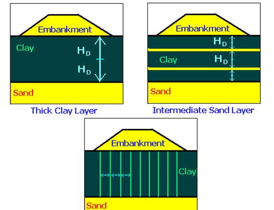
44 Drainage Path for Consolidation H D 44
45 Consolidation Theory c v = T v H 2 D / t Where c v = coefficient of consolidation in vertical direction (m 2 /year) T v = Time factor (dimensionless) H D = Drainage path length (m) t = Time application of loading (year) Rearrange t = T v H 2 D / c v Therefore 2 t H D H D 1m 10m t times faster! 45

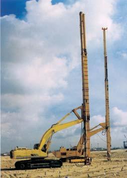
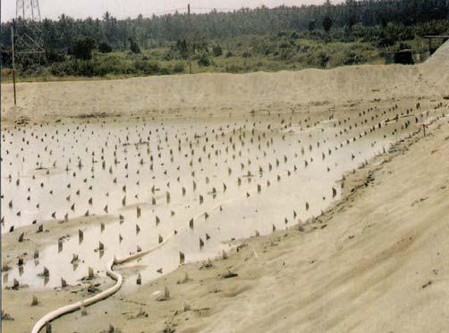
46 INSTALLED PVD 46

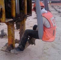
47 Cutting PVD PVD INSTALLATION VIDEO 47
48 SOME SOLUTIONS TO CULVERTS Final Profile O.G.L. Long Term Profile Silt ENLARGED CULVERT 48
49 Final Profile Long Term Profile Transition Embankment Piles Pile TRANSITION PILES Transition Embankment Piles x SOME SOLUTIONS TO BRIDGE APPROACHES 49

 http://www.nhi.fhwa.")

50 Final Profile Abutment Long Term Profile O.G.L. Pile Expanded Polystyrene (EPS) USE OF LIGHT WEIGHT MATERIAL E.P.S. Photo(1) 50
")
 51")
51 E.P.S Photo (2) E.P.S. Photo (3) 51

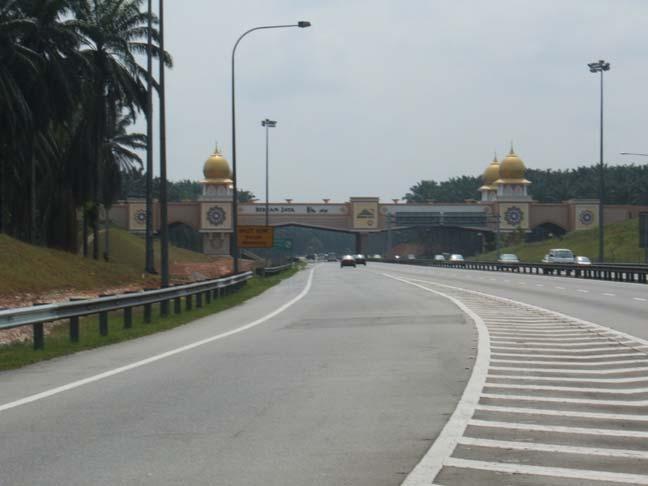
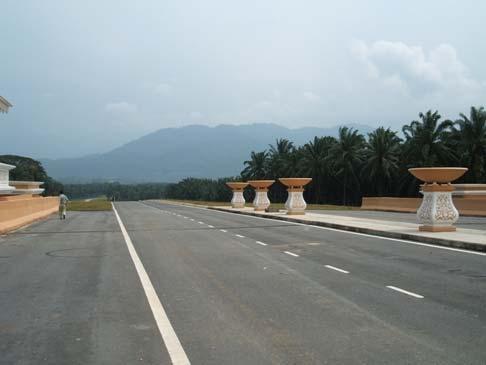
52 Final Profile Abutment Long Term Profile O.G.L. Pile Approach Slab Transition Embankment Piles USE OF TRANSITION EMBANKMENT PILES EXAMPLE (BERNAM JAYA) Transition Piles + Surcharging = Fewer Piles + Cost Saving 52
53 53
54 GUIDANCE NOTES ON SUBSOIL INVESTIGATION Guidance Notes on Subsoil Investigation Collect UD from BH Laboratory Test: UCT & 1-D Consolidation Test Piezocone: To detect presence of sand lenses Especially for surcharge design with or without PVD 54
55 LOCALISED WEAK ZONE Localised Weak Zone Generalised moderately conservative design line (MCL) 55
56 Localised Weak Zone If not identifies, likely to cause failure Surcharge + PVD Piled Embankment Further verify by Vane Shear Tests, Piezocones & MPs CONCLUSIONS 56
57 Important: Bearing Capacity assessment by CRUDE check Carry out DETAILED Analysis SYSTEMATIC check & review process (review by experienced engineers) STRUCTURED training programmes (enhance technical knowledge & share lessons learned) Full-time SUPERVISION with team of suitable experience Extra Care on TEMPORARY WORKS Plan proper SITE INVESTIGATION & FULL TIME SITE SUPERVISION Interpretation MONITOR RESULTS and Analyses DO NOT Abuse geotechnical design, detailed analysis Overlook localised weak zones Overlook structural detailing 57

58 Conclusion APPLICATIONS Conventional Surcharge Vertical Drain Vacuum Pre-loading Non-conventional Work with nature let it settles Floating settles together EPS foam reduces weight 58

59 Softwares (Computer Programmes) are TOOLS and not ENGINEERS SOFT GROUND CONSTRUCTION G&P Geotechnics Sdn Bhd ( 59