29 September Dan Hitchell, Vice President of Finance & Operations Trinity College 300 Summit Street Hartford, CT 06106
|
|
|
- Jared Walker
- 5 years ago
- Views:
Transcription

1 29 September 2016 Dan Hitchell, Vice President of Finance & Operations Trinity College 300 Summit Street Hartford, CT Reference: Broad Street - Dear Mr. Hitchell: The following report presents our findings from the structural investigation of the collapse of the rear decks at Broad Street in Hartford, Connecticut on September 10, For the purposes of this report, Broad Street runs in the north-south direction, and the decks are located on the west elevation of Broad Street. Executive Summary Based on site investigation and analysis, and with a reasonable degree of engineering certainty, we conclude that the failure of the rear elevated decks at Broad Street was primarily caused by construction flaws in some of the deck framing connections that resulted in a deficiency in capacity relative to building code requirements, engineering principles and general best practice. The under-strength connections gradually corroded over time, due to exposure to the elements, offering less and less support for the deck until the point when the occupancy loading exceeded the capacity of the south-east connection of the second floor deck triggering collapse on September 10, These conclusions are based on visual examinations made after the incident occurred. We reserve the right to supplement or amend these findings should new information become available. Background On the night of 10/September/2016 during a student party for which the decks were being used as social gathering space, the second and third floor elevated decks collapsed. Police interviews, as verbally described by detectives on site during our investigation, determined that there were approximately 4 people on the third floor deck and 7 to 10 people on the second floor deck at the time of collapse. Reports described sounds of cracking made prior to the full collapse. Unofficial news reports describe the third floor as falling first then the second collapsing right after as well as decks tipping to one side as they fell.
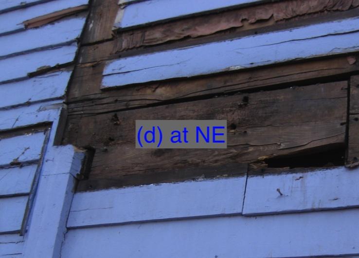
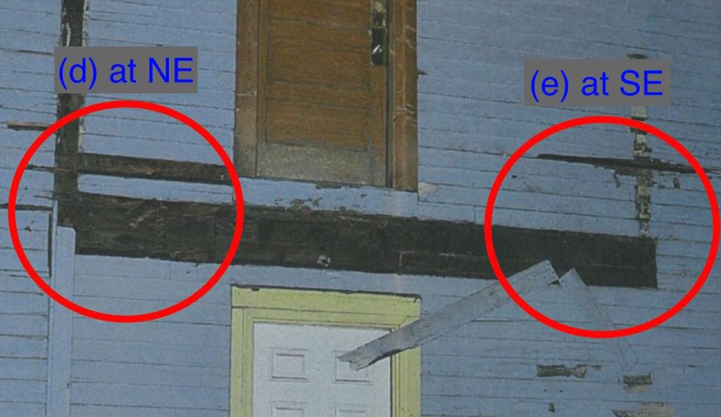
2 Approach Cirrus Structural Engineering was engaged to perform a structural investigation to identify failure modes in the framing and determine probable cause. An examination of the framing was conducted on site by the undersigned as well as Sergio Guindon from Cirrus Structural Engineering on 14/September/2016. A visual examination of fallen deck members was made from the ground as well as from a ladder. Framing and fastener sizes, spacing and condition as well as failure patterns were observed in the field. Photographs were taken to document the examination. Building Description Broad Street is a 3-story balloon-framed residential structure with a front-facing gable roof constructed circa The front of the building faces east, while the back faces west. The decks of interest are located on the rear elevation. The rear decks under study are stacked into three stories, with a deck serving each of the house levels. The second and third floor decks are elevated while the first floor sits slightly above grade. For the purposes of this report, the first, second and third story decks will be called Deck 1, Deck 2 and Deck 3 respectively. Deck 1 is approximately 8-3 x 12 in plan dimension, Deck 2 roughly 5 x 12 and Deck 3 is roughly 5 x 13. The decks under investigation were largely rebuilt at some point in the last 30 years using pressure preservative treated lumber with a few remnants of the original structure included in the reconstruction. Although the exact date of reconstruction is unknown, we suspect that the decks were rebuilt between 1990 and We found clearly legible lumber stickers on the unfinished edges of handrails and joists. The tags indicate a CCA pressure preservative treatment whose use was replaced by ACQ in Based on the construction methods, it is our opinion that the deck framing was not engineered but rather designed on-site by a contractor whose design would have been bound by Connecticut Building Code. The framing for each deck is described below including an itemized list of each of the framing members, roughly tracing the load path from point of origin down to the vertical support for the deck. Each member is identified by a letter, which is keyed into the images in the appendices to visually describe the framing. Original indicates probable original 1925 deck members; replacement indicates reconstructed members. Deck 1 The deck framing for Deck 1 did not appear to be affected or lend information to the investigation, so we will not describe it here for brevity. Deck 2 The deck framing for Deck 2 appears to have been completely rebuilt with the exception of the original 1925 ledger along the wall of the house onto which a new ledger was mounted. We observed abandoned original 4x4 outrigger beams cut-off at the main wall of the house. Deck 2 framing members include: (a) Decking on second floor joists, 2 nominal decking on 2x6 joists at 16 o.c., north-south spanning, replacement. (b) Second floor flush framed beams, (1) 2x6, supporting joists on north and south ends of deck, east-west spanning, flush-framed with joists, replacement. (c) Second floor ledger along the house wall, replacement 2x6 mounted to original 2x6 with 2 rows of 4 nails with penetration limited to thickness of original ledger; original 2x6 mounted to main wall studs through the sheathing with (2) original nails per stud. (d) Second floor north-east (NE) vertical support, replacement 2x4 bracket post, original cut-off 4x4 outrigger beam visible and sandwiched in between ledger / beam connection and replacement 2x4 bracket post below. 2.
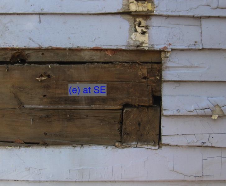
3 (e) Second floor south-east (SE) corner, 2x6 beam nailed into end grain of original ledger with (2) nails, inclusion of vertical load resisting member or bearing not present as other corners, load transfer in this corner relies on indirect load transfer through nails from beam to ledger, then nailing from original ledger back to stud walls of the house. (f) Second floor north-west (NW) and south-west (SW) vertical outer post supports, 4x6, replacement. Deck 3 The joist framing for Deck 3 appears to have been rebuilt on the original x4 beam frame. Deck 3 framing members include: (g) Decking on third floor joists, 2 nominal decking on 16 o.c joists, north-south spanning, top-framed onto original 4x4 beam frame, replacement. (h) Third floor outrigger beams, 4x4, load-bearing part of original beam frame, supporting joists on north and south ends of deck, east-west spanning, joists top-framed, original. (i) Third floor tying beam, 4x4, located along the west edge of the deck and served to tie the two outside posts together, original. (j) Third floor north-east (NE) vertical support, 2x4 bracket post, installed below beam connection, replacement. (k) Third floor south-east (SE) vertical support, 4x4 bearing bearing on 1 main house wood wall sheathing, original. (l) Third floor north-west (NW) and south-west (SW) vertical outer post supports, 4x6, replacement. Building Code Requirements We estimate that these residential decks were reconstructed sometime between 1990 and During that time the governing building code would have been the Connecticut State Building Code dated 1989, 1994 or All three codes reference CABO One and Two Family Dwelling Code dated 1986, 1989 and 1995 respectively. The CABO One and Two Family Dwelling Code is the precursor to the International Residential Code (IRC), which was first published in 2003 and first introduced in the 2004 Amendment to the 1999 State Building Code in Connecticut. The general design stipulations in both the CABO and IRC begin with an article describing the general performance requirements for buildings and structures. While each version is worded slightly differently, the meaning and intent of the article remain unchanged today since first published in CABO. The clause of interest, an excerpt from IRC 2009, describing the general performance requirements follows. R301.1 Application. Buildings and structures, and all parts thereof, shall be constructed to safely support all loads, including dead loads, live loads, roof loads, flood loads, snow loads, wind loads and seismic loads as prescribed by this code. The construction of buildings and structures in accordance with the provisions of this code shall result in a system that provides a complete load path that meets all requirements for the transfer of all loads from their point of origin through the load resisting elements to the foundation. Live loads are defined as the loads produced by use and occupancy of a structure. Both CABO and IRC define the minimum uniformly distributed live load capacity for decks during the period of probable construction to be 40 pounds per square foot (psf) of structure area. 3.
4 Observations Our investigation revealed the following observations and conditions. Photographs illustrating the points made in this section follow in the Appendices. 1. LIVE LOAD COMPARISON. Based on reported occupancies we calculated an equivalent uniformly distributed live load (see Building Code Requirements section above for definition) by multiplying the number of occupants by an assumed average weight of 200 lb per person to get a total estimated weight of the occupants, which we then divided by the square footage of the deck. The resulting equivalent uniformly distributed live load is approximately 33 psf at Deck 2, and 13 psf at Deck 3 assuming that occupants were uniformly distributed. As noted above, the code-prescribed uniformly distributed minimum live load capacity is 40 psf. Based on our estimated equivalent live loads, it does not appear that occupancy on either deck at the time of the failure on September 10, 2016 exceeded code-prescribed minimums for design. 2. DETERIORATION OF ORIGINAL 1925 LEDGER AND NAILS AT DECK 2. A ledger is defined as the structural member in the plane of the deck framing located directly against and fastened to the main wall of the house onto which the deck is attached. At Deck 2 the original 1925 ledger was retained against the house onto which a new ledger was mounted. The original ledger was fastened to the main house studs with 2 nails per stud at 16 on center. The new ledger was mounted to the original ledger with 2 rows of 4 nails; the new nails did not penetrate through the original ledger to the studs; thus the replacement deck relied on the original 1925 ledger nails to transfer ledger loads back to the main house wall. The reconstructed deck did not include flashing over the ledger, a general best practice, to protect the ledger and fasteners from precipitation draining off the deck. As a result, the original 1925 ledger and its fasteners deteriorated and corroded over time, to the point of significant section loss and reduction of capacity. 3. LACK OF DIRECT SUPPORT FOR EAST END OF DECK 2 SOUTH BEAM. Unlike the east end of the deck 2 north beam supported on the house wall by the 2x4 bracket post (d), or the deck 3 south beams supported by bearing into a pocket (k) in the house wall, the east end of the south beam was not directly supported by other structure. Rather, 2 nails were used to transfer loads from the beam into the end of the original 1925 ledger. As described in Item #2 above, the original ledger was supported by 2 nails into each stud. The nearest nailed ledger connection into the stud was approximately 12 north of the south-east corner. The size and quantity of nails was not adequate to support the loads from the beam end, especially with the 12 offset between the beam end and stud. In addition, severe corrosion on the ledger and nails undermined its capacity to support any load. Absence of a direct support for the east end of the beam is in direct violation of the code requirement for a continuous load path as described above. 4. DECK 3 BEAM DETERIORATION. Deterioration of the Deck 3 beam frame was observed, primarily in the south beam. The first photograph in the appendix shows the deck intact prior to collapse and does not indicate any major section loss of these members. Compression of wood on the top surface of these members, however, and subsequent settling in the deck above would have been likely. Loss of deteriorated wood would have most likely occurred during the impact from the deck collapse. 5. MINIMAL BEARING AT DECK 3 SOUTH OUTRIGGER BEAM. The deck 3 south outrigger was intended to bear on lumber blocking spanning between two main wall studs; however, hole in the sheathing for the outrigger did not quite align with the blocking; therefore, the bearing was supported entirely on the 1 nominal exterior sheathing of the main house. The bearing connection was not adequate to support minimum code-prescribed uniformly distributed live loads, and did not have the capacity to restrain the deck against lateral movements. 4.
5 6. BEST PRACTICE CONSTRUCTION METHODS NOT FOLLOWED. Since 2003, the IRC has become increasingly responsive to common deck construction weaknesses susceptible to failure, and has developed a number of best practice construction methods to improve performance as published in a sister document to the IRC titled Prescriptive Residential Wood Construction Guide (DCA6) by the American Wood Council. The reconstructed decks at Broad Street most likely predate the formal publication of best practices; however, the list is a useful tool in identifying overall vulnerabilities and explaining areas of weakness found on site. Best practice details for decks include knee bracing of outboard posts, use of joist hangers to support joist ends in lieu of end grain nailing, flashing above the ledger to protect the fasteners from water and corrosion, post base and cap hardware to tie beams into the posts in lieu of toenails, lag screws fastening ledgers to the main wall of the house in lieu of nails, and tension ties at main house wall to restrain the deck laterally. The reconstructed decks did not incorporate any of these best practice details. Conclusions It is our opinion that the deck failure was initiated at the south-east corner of the second floor deck where the edge beam was not directly bearing on the main wall of the house or a supplemental post as at other corners. Instead, sub-capacity nailing between the beam and ledger, and ledger and main wall studs, were supporting the beam end. The sub-capacity nailing was able to support the south-east corner of the second floor deck for many years by bolstering additional support from the vertical rail attachment above the beam and nailed directly into the main wall of the house. A chain reaction started by the contractor s failure to replace the original 1925 second floor deck ledger and its fasteners, and subsequent corrosion due to the absence of protective flashing above, caused the nails to become so severely corroded that their capacity was overwhelmed by the occupants of the deck on September 10, Downward movements in the south-east corner of the second floor deck most likely caused upward and/or lateral movements in the north-west corner which were transferred to the third floor deck. The third floor deck, having limited bearing of the beam at its south-east corner, was most likely the first to fully collapse causing the subsequent collapse of the second floor deck. Respectfully Yours, Cirrus Structural Engineering, LLC Elizabeth Acly, PE Principal 5.
6 Appendices: Images Corresponding to General Description Section pages 7 to 12 Images Corresponding to Observations Section pages 13 to 15 Key to Member Designations: (as repeated from Building Description section of main report) Deck 2 Deck 3 (a) Decking on second floor joists, 2 nominal decking on 2x6 joists at 16 o.c., northsouth spanning, replacement. (b) Second floor flush framed beams, (1) 2x6, supporting joists on north and south ends of deck, east-west spanning, flush-framed with joists, replacement. (c) Second floor ledger along the house wall, replacement 2x6 mounted to original 2x6 with 2 rows of 4 nails with penetration limited to thickness of original ledger; original 2x6 mounted to main wall studs through the sheathing with (2) original nails per stud. (d) Second floor north-east (NE) vertical support, replacement 2x4 bracket post, original cut-off 4x4 outrigger beam visible and sandwiched in between ledger / beam connection and replacement 2x4 bracket post below. (e) Second floor south-east (SE) corner, 2x6 beam nailed into end grain of original ledger with (2) nails, inclusion of vertical load resisting member or bearing not present as other corners, load transfer in this corner relies on indirect load transfer of nails from beam to ledger, then nailing from original ledger back to stud walls of the house. (f) Second floor north-west (NW) and south-west (SW) vertical outer post supports, 4x6, replacement. (g) Decking on third floor joists, 2 nominal decking on 16 o.c joists, north-south spanning, top-framed onto original 4x4 beam frame, replacement. (h) Third floor outrigger beams, 4x4, load-bearing part of original beam frame, supporting joists on north and south ends of deck, east-west spanning, joists topframed, original. (i) Third floor tying beam, 4x4, located along the west edge of the deck and served to tie the two outside posts together, original. (j) Third floor north-east (NE) vertical support, 2x4 bracket post, installed below beam connection, replacement. (k) Third floor south-east (SE) vertical support, 4x4 bearing bearing on 1 main house wood wall sheathing, original. (l) Third floor north-west (NW) and south-west (SW) vertical outer post supports, 4x6, replacement. 6.

7 Decks Intact Prior to Failure 7.
8 Broad Street 28 September 2016 c a b e d f f NE SE NW SW Second Floor Deck Exploded Framing Sketch (DECK 2) 8.

9 Underside of Second Floor Deck Framing (DECK 2) 9.
10 Connection of Second Floor Deck to Main House (DECK 2) 10.
11 Broad Street 28 September 2016 g g i k h h j l l NE SE NW SW Third Floor Deck Exploded Framing Sketch (DECK 3) 11.
 12.")
12 Underside of Third Floor Deck Framing (DECK 3) 12.


13 Broad Street 29 September 2016 #2. Deteriorated Deck 2 original 1925 ledger and nails #2. Corroded Deck 2 nails 13.


14 #3. Deck 2 South-East Beam End Connected to Ledger with only 2 nails; SE beam end not extended to bear onto main house wall #4. Deck 3 Deterioration at West End of South Beam 14.

15 #5. Deck 3, Wall Bearing Support at East End of South Beam 15.