Residential Decks 1 & 2 Family Dwellings and Townhouses
|
|
|
- Merilyn Wheeler
- 5 years ago
- Views:
Transcription


1 Municipality of Bethel Park Residential Decks 1 & 2 Family Dwellings and Townhouses Responsibility for compliance with applicable codes and ordinances falls on the owner or contractor. For specific questions regarding code requirements, refer to the applicable codes or contact your local Building Department. Building Permits Requirements: Building permits are required for the construction of all attached or freestanding decks that are elevated 30 or more above grade. Deck construction shall meet the requirements of the 2015 International Residential Code. 30 or more above grade Zoning Requirements: Any deck construction requires a property survey and will need to meet the land use and setback requirements of the Municipal zoning code. (See example) Plan Review & Inspections: The plan is reviewed by the plans examiner in order to identify potential problems that may arise prior to construction. Construction inspections will be done during the project to ensure code compliance and that the materials used are installed correctly. 1 12/18
2 Builders and homeowners are required to obtain a permit prior to constructing, altering or replacing a deck. The following are examples of information that should be included on plans submitted for building permits for residential decks. They are examples only and should not be construed as being code compliant for every application. It is the responsibility of the homeowner or person preparing the plans to show in detail how they will build their deck. Some designs may require more detail than others. Your deck plans should replicate exactly how you will build your deck. We will review your plans before we issue the building permit to verify code compliance before you start work. The more detailed your plans, the more likely you will avoid mistakes during construction. Once your plans are approved, you should not change your design without approval by Bethel Park Building Inspection Division. You should read through the approved plans to determine if the plan reviewer noted any corrections to your plan. If you have any questions regarding any of the corrections you should contact us before proceeding. Permit applicant is responsible for scheduling all inspections. Plans created at home centers are seldom acceptable for plan review. These computer designs do not allow homeowners to duplicate actual conditions at their home. Some of these plans may be modified to include all necessary information prior to submittal. Applications submitted with these types of plans without additional modifications will be returned to the applicant. THINK YOU MIGHT ENCLOSE YOUR DECK IN THE FUTURE? Deck plans are approved on the assumption that the deck will be used only as a deck for the life of the structure. Because footing sizes, setbacks, structural supports and a host of other deck components are different for enclosed porches than for decks. It is important that you indicate on you plans the desire to convert the deck at a future date. You should then design your deck to carry future loads and meet setbacks and other rules. 12/18 2
3 Flashing extended from behind siding & housewrap over ledger board TYPICAL DECK CROSS SECTION Min. 5/4 wood decking material Note: All flashing, fasteners and connectors must be compatible with materials used. Guardrail shall be a min. of 36 high & spacing between in-fill shall be less than 4 apart. Joists shall be positively connected to beam. See pg 6 24 max. cantilever Joist hanger approved for treated wood & Joist size 2 1/2 bolts dia. min. 12 o.c. or 6 o.c. staggered (on center) Note: emergency escape windows are allowed to be installed under decks and porches provided the locations of the deck allows the emergency escape window to be fully opened and provides a path not less than 36 in height to a yard or court. 6 8 required for walk out basements or patios. 6 8 Treated joists, 16 o.c. Finished grade 2 - ½ thru bolts Connector column to pier Type A Grade Treated beam 6X6 treated Column Type B Gravel, dirt, crushed rock or pea rock Type C FOOTINGS BeFore you Dig Call 811 for utility locations at least two working days before you dig 36 MINIMUM FROM FINISHED GRADE TO BASE OF FOOTING 8 MIN. CONRETE BASE Earth 24 Min WIDTH OF FOOTING AT BASE To accurately size footings, beams and joist refer to tables on pgs 16. Beam and Footing Sizes Maximum Joist Span WARNING: THIS IS AN ILLUSTRATION ONLY. IT IS INTENDED TO SHOW SOME OF THE INFORMATION THAT SHOULD BE INCLUDED ON YOUR DECK PLANS. IT IS NOT INTENDED TO SHOW COMPLIANCE WITH ANY CODES THAT MAY APPLY. CHANGES IN THE HEIGHT AND SIZE OF A DECK WILL CAUSE VARIATIONS IN CODE REQUIREMENTS. 12/18 3


4 DECK FRAMING Ledger Board Connection The ledger board attaches to the house frame or foundation. Make sure the ledger is securely attached to the dwelling. Install metal flashing at top, and caulk sides and bottom. General Attachment of Ledger Board to House Band Joist/Rim Board Tuck flashing under siding & housewrap 7 ¾ max. Step down between finished interior floor and deck platform Flashing 1/2 or Optional CONCEALED FLANGE HANGER No Attachment to or Through Exterior Veneers (Brick, Masonry, Stone) 12/18 Bolts with washers shall penetrate thru solid backing CONVENTIONAL HANGER Metal Plate Connected (MPC) Wood Floor Trusses with a 2x4 Lumber Ribbon at the Ends of the Trusses No Attachment to Over Hangs 4

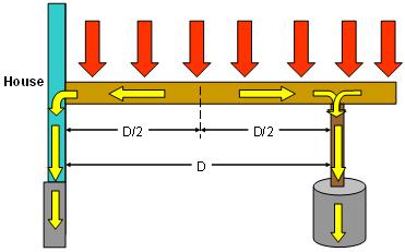
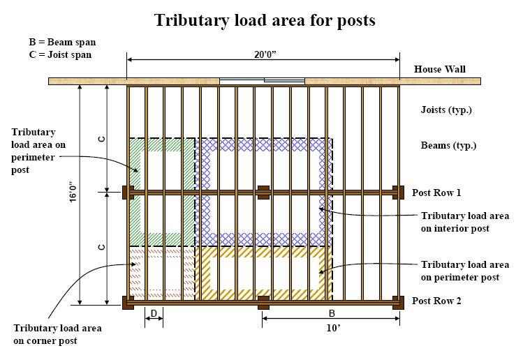

5 Understanding Load Paths Tributary is half the distance: of the joist or to the post. 12/18 5


6 Type A Attaching: Beam to Post Illustrations METHODS OF ATTACHING BEAM TO COLUMN BEAM SECURED WITH POST CAP BEAM SECURED WITH BOLTS TO NOTCHED POST Type B BEAM SPLICES OK Type C Construct the beam using two or more 2 inch nominal pieces of lumber. Nail the beam together using 10d - 16d nails at 16 inches o.c. along each edge of the beam. A spacer may be used to fir the beam to a 3½ -inch width. Beams should be installed with any arch or crown facing up. JOIST-TO-BEAM CONNECTION Each joist shall be attached to the beam as shown. Use Option 1 or Option 2 when joists bear on or overhang past the beam. Use Option 3 when joists attach to the side of the beam. 12/18 6


7 Cantilever Options All thru bolts and lag screws shall be installed with washers. Lag screws or bolts shall be placed two inches from the bottom and top of deck ledgers and between two to five inches from the ends. Lag screws or bolts shall be staggered from the top to the bottom along the horizontal run of the deck ledger. Cantilever Warning: Do not exceed capacity of connectors when supporting ends of beams. 2 Min to 5 max from end of ledger 2 Min from top and bottom of ledger Alternate design: Cut beam into house framing with solid blocking to wall plates. Additional support posts may be required depending on span of cantilever & size of deck. WARNING: CAPACITY OF LAG OR CARRIAGE BOLTS SHALL NOT EXCEED 400 LB S PER BOLT UNLESS AN ENGINEERED DESIGN IS PROVIDED. 7


8 Guards on deck platform 36 minimum in height. Guard height at stairs is minimum 34 vertical from stair tread 36 Min. A TYPICAL STAIR FRAMING DETAIL 4 3/8 Diameter sphere may not pass through Handrail height is min. 34 to 38 max Handrail for stairways shall be continuous for the full length of the flight and returned at the top and bottom newel post. Handrail required with 4 or more risers Height of the deck is measured from the top of the platform to finish grade. 4 Diameter sphere may not pass through Proper strap required to secure stringers to header. 8 1/4 Max rise 3 2 x 12 stair stringers #2 SYP treaded. 9 Min run 4 diameter sphere may not pass through risers over 30 above grade. Min. Stair Width 36 All field cuts shall be treated Stairway illumination. All interior and exterior stairways shall be provided with a means to illuminate the stairs, including the landings and treads. The illumination of exterior stairways shall be controlled from inside the dwelling unit. Lights that are continuously illuminated or automatically controlled can be used. Solar lighting is NOT approved. Reinforced Post Connections (Three dimensional view) lags bolts The leverage from a deck railing post will twist the rim joist unless the rim joist is securely fastened to the joist end or perpendicular blocking. ½ carriage bolts are required for resisting code design loads. 12 8

9 Electrical service lines over or within 3' horizontally of the deck or stairs must have a minimum 10' vertical clearance. GENERAL INFORMATION: RAILINGS Guardrails are required for portions of decks 30 or more above grade. The height of the rail must be a minimum of 36. Open guardrails must have intermediate rails or an ornamental pattern that a 4 sphere cannot pass through. Guardrails must continue down stairs where the stair is more than 30 inches above grade. STAIRS Stairs must have a maximum rise of 8 1/4 inches and a minimum run of 9 inches. The run is measured from the nosing of one tread to the nosing of the next. The greatest riser height within any flight of stairs shall not exceed the smallest by more than ⅜ inch. The greatest tread depth within any flight of stairs shall not exceed the smallest by more than ⅜ inch. Maximum step down is 7 3/4 from interior finished floor to top of the deck platform at the patio door. Open risers are permitted provided that a 4 diameter sphere will not pass thru the opening between the treads. SAFTEY GLAZING All glass (windows) shall be reviewed for tempered glazing requirements. Be sure to show location of all windows in relation to deck stairs, landings, top and bottom treads, and walking surfaces. WOOD TREATMENT Wood used above ground, in contact with the ground, or below ground requires different degrees of treatment. Check the labels of the material you are buying to determine where it can be used. Because the new preservative treatments are very corrosive, make sure that any metal connectors used in the construction of your deck are approved by the manufacturer for use with treated wood. DECKING Caution some manufactured deck products are approved for decking but not for stair treads. In some cases where manufactured decking is approved for stairs, the spacing of supports may be significantly reduced compared to use on the deck itself. Read the research report for further information. 9
10 INSPECTIONS The Building Department will typically make at least three (3) inspections of your deck. It is your responsibility to call for an inspection 24 hours in advance of the time you need an inspection. When you call for an inspection, you will be asked for your address, the type of inspection you desire (footing, framing, final), the permit number (which is found on your building permit), and the time you want the inspection. We will make every effort to accommodate requests for inspections at specific times. Applicant is responsible for scheduling all inspections. The first inspection will be of the post footings. At the time of the inspection, property pins shall be exposed, the holes should be dug and all loose material should be removed but no concrete should be poured. The inspector will check the depth of the footing and it s width at the base. They shall also check the location of the footings for compliance with the zoning ordinance. If you are having problems with water seeping into the hole, you may wish to insert a large plastic garbage bag into the hole and pour the concrete into the bag to displace water without compromising the concrete. The next inspection is the framing inspection. The inspector will check the size and spacing of joists, beams and columns, the attachment to the dwelling including flashing, the type of fasteners and lumber being used, type of decking used, railings, stairs, and landings. The last inspection to be scheduled is the Final. Once the project is entirely complete, the inspector will confirm that the project in whole complies with code. If a violation is detected a notice will be prominently placed on the digital record with the correction that must be made and time limit allowed for corrections. The notice will also indicate if a reinspection will be necessary. If a re-inspection is necessary you must call for the inspection and have the correction approved before proceeding unless directed otherwise by the inspector. If at any time during the construction of your deck you have a question, please do not hesitate to call the Building Department at (412)
11 CHECKLIST FOR DECK PLANS (This information is to be provided on your plan.) Please Verify! Site Plan Street address and/or legal description shown Size/location of existing buildings, easements and buffers All lot dimensions and pin locations shown Location and size of proposed deck shown Distance from all lot lines to proposed deck Locations of existing windows/doors (glass) and window wells if applicable [Tempered glass may be required at landings, walking surfaces, top or bottom tread and next to stairs.] Construction Plans Elevation A complete set of plans submitted All measurements, distances, sizes and lumber dimensions have been noted on plan Plan neat and legible Is deck connected to a cantilever? If so indicate what type of floor system the cantilever is framed with. Show side and/or front view of deck in relation to grade and dwelling Include railing height and design Framing Plan Floor joist size and spacing including species and grade Orientation of floor joists Cantilever of joists beyond beam (max. 2 feet) Bearing points for all joists Size and location of all beams including species and grade Cantilever of beams beyond post Size and location of ledger board including species and grade Size and location of all columns/post Location of stairs Changes in elevation of deck floors or landings Unusual framing issues such as cantilevers of the dwelling floor Section(s) Cross section or top view(s) from bottom of footing to top of guard to show railing details; floor framing orientation; joist/beam orientation and bearing; column locations; connections; footing design, size, and depth; and height of deck floor above grade. Details Guards Flashing at the ledger Joist bearing/hangers Ledger connection (Caution for dwelling floor cantilevers) Column/beam connection Column/footing connection Type of decking and orientation (Caution for 5/4 or composite decking for spans more than 16 o.c. or installed diagonally Provide stair stringer connection detail See examples Lateral bracing is required when the deck platform is 12 feet and greater measured from finished grade (see page 8) Width of stairs (36 minimum width) Rise/run w/tolerance shown Number and size of stringers (see page 8) Open riser design (less than 30 above grade) Type and size of tread consistent with stringer spacing (Caution for decking use) Circle handrail detail that will be used Handrail height shown on plan (see page 8) Landing at bottom of stair (grade is acceptable when within rise tolerance) Guard height and opening dimensions Guard design/materials Guard attachment Footings Footing depth and design Footing width at base consistent with load for each footing location. 11
12 CHARTS DECK LEDGER CONNECTION TO BAND JOIST, b (Deck live load = 40 psf, deck dead load = 10 psf, snow load :5 40 psf) JOIST SPAN CONNECTION DETAILS G'andless to to 10' 10'1" to 12' to 14' 14'1" to 16' 16'1" to 18' On-center spacing of fasteners 1 /2 -inch diameter lag screw with 1 / 2 -inch maximum sheathing d /2 -inch diameter bolt with 1 / 2 -inch maximum sheathing d /2 -inch diameter bolt with 1-inch maximum sheathing For SI: 1 inch = 25.4 mm, 1 foot= mm, 1 pound per square foot= kpa. a. Ledgers shall be flashed in accordance with Section R703.8 to prevent water from contacting the house band joist. b. Snow load shall not be assumed to act concurrently with live load. c. The tip of the lag screw shall fully extend beyond the inside face of the band joist. d. Sheathing shall be wood structural panel or solid sawn lumber. e. Sheathing shall be permitted to be wood structural panel, gypsum board, fiberboard, lumber or foam sheathing. Up to 1 / 2 -inch thickness of stacked washers shall be permitted to substitute for up to 1 / 2 inch of allowable sheathing thickness where combined with wood structural panel or lumber sheathing. PLACEMENT OF LAG SCREWS AND BOLTS IN DECK LEDGERS AND BAND JOISTS MINIMUM END AND EDGE DISTANCES AND SPACING BETWEEN ROWS TOP EDGE BOTTOM EDGE ENDS ROW SPACING Ledger" 2 inches d 3 / 4 inch 2 inches b I 5 I 8 inches Band Joist 0 3 / 4 inch 2 inches 2 inches b 1 5 / g irtches b For SI: l inch= 25.4 mm. a. Lag screws or bolts shall be staggered from the top to the bottom along the horizontal run of the deck ledger in accordance with Figure R507.2.l(l). b. Maximum 5 inches. c. For engineered rim joists, the manufacturer's recommendations shall govern. d. The minimum distance from bottom row of lag screws or bolts to the top edge of the ledger shall be in accordance with Figure R507.2.l(l). MAXIMUM JOIST SPACING MAXIMUM ON-CENTER JOIST SPACING MATERIAL TYPE AND NOMINAL SIZE Perpendicular to joist Diagonal to joist' 1 1 / 4 -inch-thick wood 16 inches 12 inches 2-inch-thick wood 24 inches 16 inches Plastic composite In accordance with Section R507.3 In accordance with Section R507.3 For SI: l inch= 25.4 mm, 1 foot= mm, I degree = rad. a. Maximum angle of 45 degrees from perpendicular for wood deck boards DECK POST SIZE MAXIMUM HEIGHT 8 4X4 8' 4X6 8' 6X6 14' For SI: 1 foot= mm. a. Measured to the underside of the beam. 12

. 0.. o 0- a. a -_.o o C::::, O EXISTING..., o. c;,,-.: o. o 0 FOUNDATION WALL o._. 6 JOIST HANGER For SI: 1 inch = 25.4 mm.")
13 DETAILS "MAX 2"MIN. LEDGER / z = STAGGER FASTENERS N ::!: IN2 ROWS LAG SCREW OR BOLT 5.5" MIN. FOR 2 X 8* 6.5" MIN. FOR 2 X " MIN. FOR 2 X t-- 3/4" MIN. *DISTANCE SHALL BE PERMITTED TO BE REDUCED TO 4.5" IF LAG SCREWS ARE USED OR BOLT SPACING IS REDUCED TO THAT OF LAG SCREWS TO ATTACH 2 X 8 LEDGERS TO 2 X 8 BAND JOISTS. For SI: 1 inch= 25.4 mm. PLACEMENT OF LAG SCREWS AND BOLTS IN LEDGERS EXISTING STUD WALL----, EXISTING 2x BAND JOIST OR ENGINEERED RIM BOARD DECK JOIST FLOOR FRAMING o-.. o- 6 o = - 0 <;;). 0.. o 0- a. a -_.o o C::::, O EXISTING..., o. c;,,-.: o. o 0 FOUNDATION WALL o._. 6 JOIST HANGER For SI: 1 inch = 25.4 mm. PLACEMENT OF LAG SCREWS AND BOLTS IN BAND JOISTS 13


14 DETAILS CONT'D FLOOR SHEATHING NAILING AT 6" MAXIMUM ON CENTER TO JOIST WITH HOLD-DOWN l -- HOLD-DOWN OR SIMILAR TENSION DEVICE J FLOOR JOIST DECK JOIST DECK ATTACHMENT FOR LATERAL LOADS NOTE: THIS DETAIL IS APPLICABLE WHERE FLOOR JOISTS ARE PARALLEL TO DECK JOISTS. SHEATHING SIDING FLASHING FOR WATER TIGHTNESS FLOOR JOISTS._.. APPROVED JOIST HANGERS 2x LEDGER WITH FASTENERS IN ACCORDANCE WITH TABLE R507.2 HOLD-DOWN DEVICE MIN 750 LB. CAPACITY AT 4 LOCATIONS, EVENLY DISTRIBUTED ALONG DECK AND ONE WITHIN 2" OF EACH END OF THE LEDGER. HOLD-DOWN DEVICES SHALL FULLY ENGAGE DECK JOIST PER. HOLD-DOWN MANUFACTURER. -, A FULLY THREADED 3/a'' DIAMETER LAG SCREW PREDRILLED W/ MIN. 3" PENETRATION TO CENTER OF TOP PLATE, STUDS, OR HEADER. DECK ATTACHMENT FOR LATERAL LOADS 14
15 SPECIES Southern pine DECK BEAM SPAN LENGTtts, b (ft. - in.) SIZE DECK JOIST SPAN LESS THAN OR EQUAL TO: (feet) X X X X X X X X x 6or2-2x6 3x8or2-2x x 10or2-2 x x 12or2-2 x X Douglas fir-larch, hem-fir, spruce-pine-fir, 4X redwoo d, we stern cedars, 4 X ponderosa pine\ 4 X red pine r 3-2 X X X X For SI: 1 inch= 25.4 mm, 1 foot= mm, 1 pound per square foot= kpa, 1 pound= kg. a. Ground snow load, live load= 40 psf, dead load= 10 psf, L/6 = 360 at main span, L/6 = 180 at cantilever with a 220-pound point load applied at the end. b. Beams supporting deck joists from one side only. c. No. 2 grade, wet service factor. d. Beam depth shall be greater than or equal to depth of joists with a flush beam condition. e. Includes incising factor. f. Northern species. Incising factor not included. DECK JOIST SPANS FOR COMMON LUMBER SPECIES' (ft. - in.) SPECIES Southern pine SIZE SPACING OF DECK JOISTS WITH NO CANTILEVER (inches) SPACING OF DECK JOISTS WITH CANTILEVERS (inches) x X X X X Douglas fir-larch d, 2X hem-fu<i spruce-pine-fit 2 X X X Redwood, western cedars, 2x ponderosa pine, 2 X red pine 2 X For SI: 1 inch= 25.4 mm, 1 foot= mm, I pound per square foot= kpa, 1 pound= kg. a. No. 2 grade with wet service factor. b. Ground snow load, live load= 40 psf, dead load= 10 psf, lj.i = 360. c. Ground snow load, live load= 40 psf, dead load= 10 psf, lj.i = 360 at main span, U.i = 180 at cantilever with a 220-pound point load applied to end. d. Includes incising factor. e. Northern species with no incising factor f. Cantilevered spans not exceeding the nominal depth of the joist are permitted
16 16