Project Address: Owner Name: PHONE: Your Deck Plan and Section must include all of the following:
|
|
|
- Prudence Armstrong
- 5 years ago
- Views:
Transcription
 2. Site Plan * (example enclosed) 3. Deck Plan * (form enclosed) 4. Deck Section * (form enclosed) 5. Standard Details * (form enclosed) 6.")
1 Bemidji City Hall th Street NW Bemidji, Minnesota Project Address: Owner Name: PHONE: To obtain a permit, you will need the following: 1. Deck Construction Checklist * (this form) 2. Site Plan * (example enclosed) 3. Deck Plan * (form enclosed) 4. Deck Section * (form enclosed) 5. Standard Details * (form enclosed) 6. Building Permit Application * Incomplete plans will not be reviewed. Your Deck Plan and Section must include all of the following: Deck dimensions Length: Width: Decking material: Beam(s) size: Post size: Joist size, species and grade per Joist Span Table 1 Post spacing: Corner footing bottom diameter: Joist spacing: Intermediate footing bottom diameter: Joist cantilever: (pier bottom dia. per Beam and Footing Table 2) (see Beam and Footing Table 2, footnote 2) Deck surface height above grade: Ledger connection: (decks 6 feet above grade require diag. bracing) (see ledger connection requirements Table 3) Office Use Only: Received By: Notes: Date Received: Parcel #80.0

, including septic system area and wells if applicable. ELEVATION 1. Height of structure surface from grade. 2.")

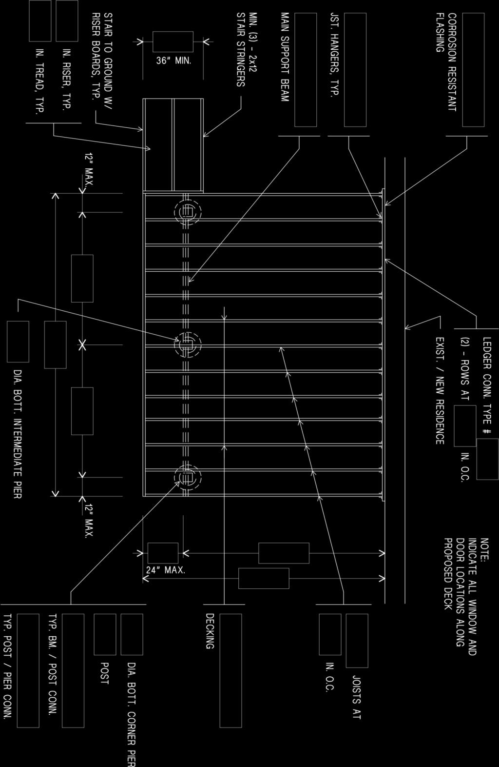
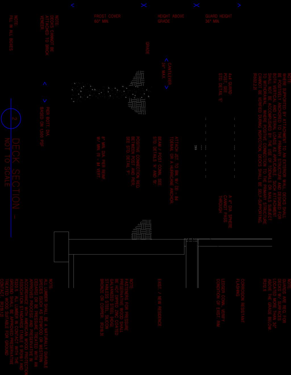
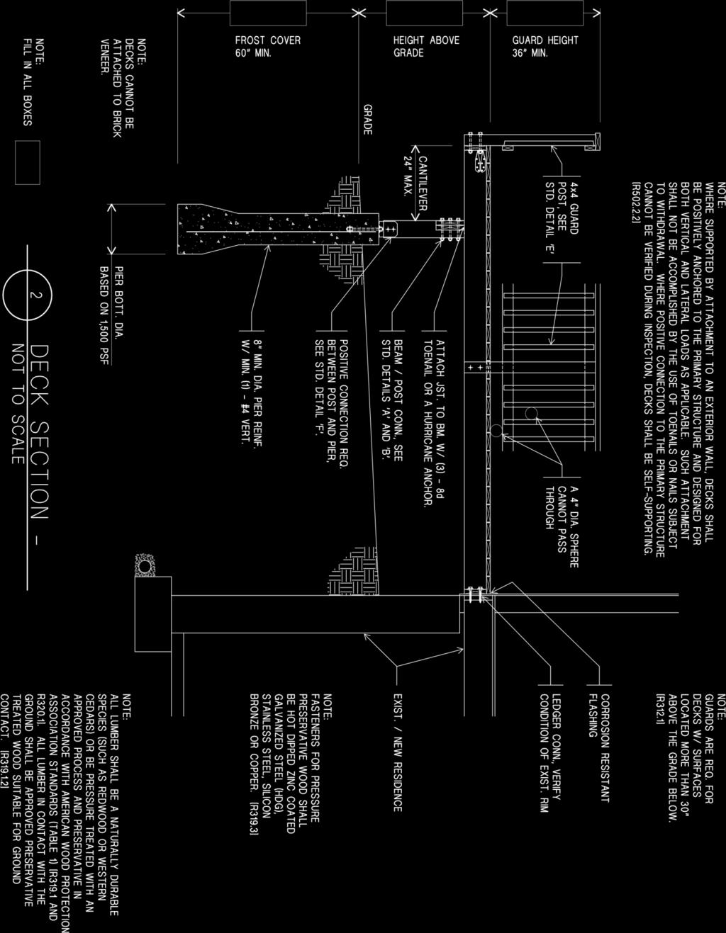
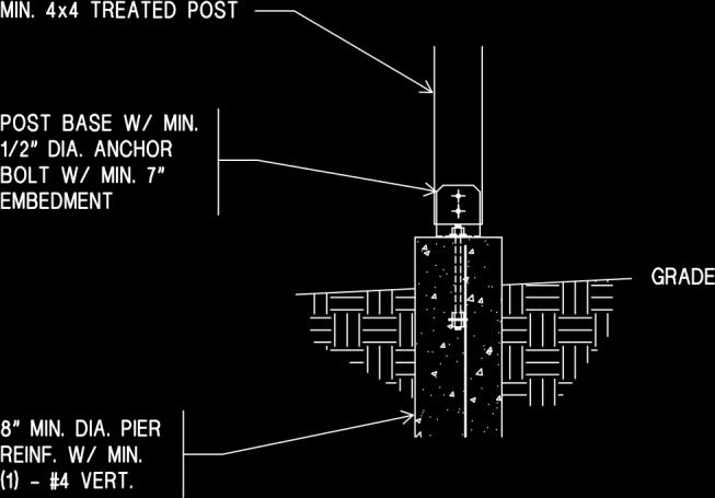
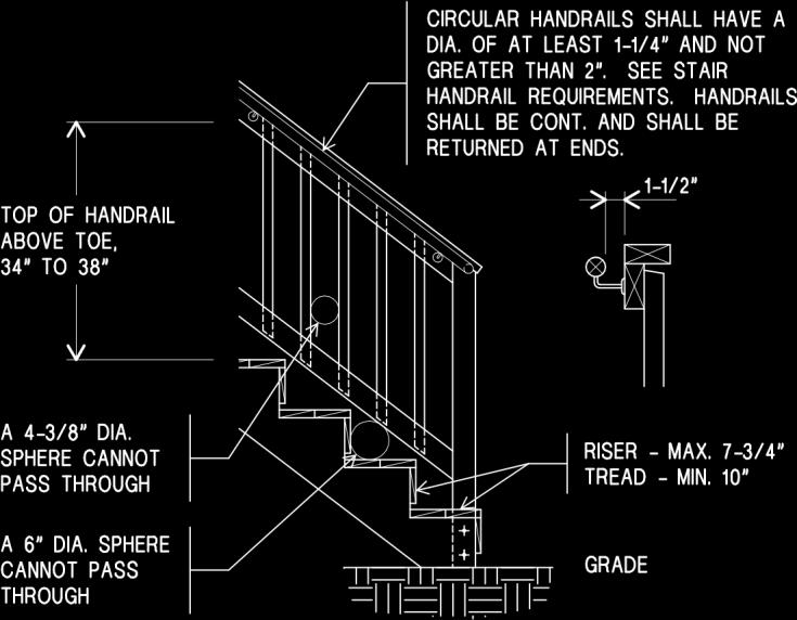
2 PLANS: SITE, DECK FRAMING, and ELEVATION The following text and sample drawings show the minimum detail expected so the permit process can proceed smoothly. TWO sets of each plan are required. Plans do not need to be professionally drawn. However, plans should include all of the information requested. The application for permit can be filled out at the time you drop off your plans. Certificate of Survey or Site Plan drawn to scale indicating the lot dimensions, the location and size of the existing structure(s), and the location and a size of the proposed structure. Indicate the setbacks from property lines of the existing and proposed structure(s), including septic system area and wells if applicable. ELEVATION 1. Height of structure surface from grade. 2. Size and depth of footings. 3. Guard height and spacing (if any). 4. Stairway rise/run and handrail height (if any). 5. Clearance of over-head wires (if applicable). 6. Gas meters cannot be located above or below a new deck. DECK FRAMING PLAN 1. Proposed deck size. 2. Size and spacing of deck joists. 3. Size and type of decking material. 4. Size, type, location, and spacing of posts. 5. Size and type of beams. 6. Size of pier bottom diameter. 7. Ledger connection.
3 Project Address: SITE PLAN Owner Name: This site plan is an accurate and complete representation of the footprint(s) of all existing and proposed structure(s) and their location(s) on the subject property. Permit # North Arrow Required! Scale: 1 box = feet N
4
5
6
7 Table 3: Ledger Connection Requirements Fastner Spacing For a Southern Pine or Hem-Fir Deck Ledger and a 2 inch Nominal Solid Sawn Spruce Pine Fir Band Joist c,f (Deck Live Load = 40 psf, Deck Dead Load = 10 psf) Joist Span 6' and less 6'-1" to 8' 8'-1" to 10' 10'-1" to 12' 12'-1" to 14' 14'-1" to 16' Connection Details (2) - Rows of On-Center Spacing of Fasteners d,e 1/2 inch diameter lag screw with 15/32 inch maximum sheathing a /2 inch diameter bolt with 15/32 inch maximum sheathing /2 inch diameter bolt with 15/32 inch maximum sheathing and 1/2 inch stacked washers b,g a. The tip of the lag screw shall fully extend beyond the inside face of the band/rim joist. b. The maximum gap between the face of the ledger board and face of the wall sheathing shall be 1/2 inch. c. Ledgers shall be flashed to prevent water from contacting the house band/rim joist. d. Lag screws and bolts shall be staggered. e. Deck ledger shall be minimum 2x8 pressure preservative treated No. 2 grade lumber, or other approved materials as established by standard engineering practice. f. When solid sawn pressure preservative treated deck ledgers are attached to a minimum 1 inch thick engineered wood product (structural composite lumber, laminated veneer lumber or wood structural panel band/rim joist), the ledger attachment shall be designed in accordance with accepted engineering practice. Wood structural panel sheathing, gypsum board sheathing or foam sheathing not exceeding 1 inch nominal in thickness shall be permitted. The maximum distance between the face of the ledger board and the face of the band/rim joist shall be Lag Screws: Lag screws shall have a minimum diameter of 1/2 inch. Lag screws may be used only when the field conditions conform to those shown above. All lag screws shall be with washers. Thru-Bolts: Thru-bolts shall have a diameter of 1/2 inch. Pilot holes for thru-bolts shall be 17/32 inch to 9/16 inch in diameter. Thru-bolts require washers at the bolt head and nut.