Tip-Grouted Drilled Shaft Foundations for the Audubon Bridge. Acknowledgements
|
|
|
- Arron Robinson
- 5 years ago
- Views:
Transcription
1 Tip-Grouted Drilled Shaft Foundations for the Audubon Bridge Steven Dapp, Ph.D., P.E. Dan Brown, Ph.D., P.E. Acknowledgements Tip grouting used worldwide for more than 3 decades. Six years of research at USF, funded by the FDOT, has produced a rational design procedure. Gaining wide acceptance within the US. 1
2 Outline The Tip Grouting Process The Benefits of Tip Grouting Experiences: U.S. and Abroad John James Audubon Bridge (1) As constructed, un-stressed. The Tip Grouting Process (2) Grout pressure applied, negative side shear reaction. (3) Some Relaxation occurs. (4) Structural load applied. 2


3 Tip Grouting Process Grouting Injection Mechanisms Stem or Orifice (Not Shown): Consider as a Remediation Option Only. 3


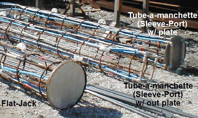
4 Not Grouted Flat-Jack Tube-a-Manchette Benefits of Tip Grouting Increases the ultimate tip capacity. Tip component able to contribute to the useful capacity (i.e., within tolerable displacements). Provides a proof load of capacity for every grouted shafts on the site. 4

5 Benefit with Soil Type Cohesionless Soils: Significant improvement as well as proof s the load. Most improvement seen in loose to medium dense sands. Cohesive Soils: Little improvement, but proofs the load. Differential Settlement in Soils Associated with End Bearing Rock Socket: May be used to remediate soft toes in deep excavations (long construction times) where thorough clean-out can not be achieved/assured. Grouting Procedures / Criteria Sustained Grout Pressure: Develops and proves the increase in useful tip resistance. Excessive Grout Volume (without achieving grout pressure): Stop, flush lines, and try staged grouting technique later. Shaft Uplift (without achieving grout pressure): Side shear is not as great as anticipated, and is inadequate to provide reaction for grout pressure. 5
6 When to Consider Tip Grouting Sandy bearing stratum Shaft tip cleanliness is difficult to achieve and/or maintain. Increase reliability by proof loading every shaft. Reese & O Neil (1988, 2000) Mullins, A.G., Winters, D., and Dapp, S.D., (2006) Predicting End Bearing Capacity of Post-Grouted Drilled Shaft in Cohesionless Soils J. Geotech. and Geoenvir. Engrg., Volume 132, Issue 4, pp TCM = ( GPI ) (% D) (% D) (% D) TCM = 0.4 (% D) (% D)


 Taiwan,")
7 2006 My-Thuan Bridge Vietnam (1998) 2006 Taipei Financial Center (a.k.a. 101 ) Taiwan,


8 Experience with Tip Grouting in the U.S. 10 projects since were DOT bridges (Florida, Mississippi, Texas and South Carolina. 4 were commercial High Rise (Florida). Nearly 600 tip grouted drilled shafts, with 17 full scale load tests. Dapp, S.D., Muchard, M., Brown, D.A., Experiences with Base Grouted Drilled Shafts in the Southeastern United States. DFI 10th International Conference on Piling Foundations, Ghent, Belgium. John James Audubon Bridge SR10 over the Mississippi River 1,583 ft Cable Stayed Span, Longest in North America $347 million, Design-Build Project 8
9 SPT "N" (blows/ft) Silty Sands 0-50 Elevation (ft) Sand Sand with Layers of Sandy G l Shaft Tip Elevation Clay Soils Undrained Shear Strength (tsf) -300 Shaft Tip Elevation (feet) Scour (Global) Grouted Tip Elevation Steel Casing Tip Reaction for Grout Pressure (Side Shear / W'shaft) Ultimate Side Shear (Sands / Gravels) Ultimate Side Shear (Clay Soils) Grout Pressure Limited to 750 psi Transition to Clay Cased Shaft Diameter = 8 ft Un-Cased Nom. Diam. = 7.5 ft ,000 1,500 2,000 2,500 3,000 3,500 4,000 4,500 5,000 5,500 Side Shear Resistance (tons) 9
10 Shaft Tip Elevation (feet) Steel Casing Tip Grouted Tip Elevation Transition to Clay Ungrouted Grouted End Bearing Resistance at a Displacement of 3% Diam. (2.7-inch) Cased Shaft Diameter = 8 ft Un-Cased Nom. Diam. = 7.5 ft ,000 1,500 2,000 2,500 3,000 3,500 4,000 4,500 5,000 End Bearing Resistance (tons) Shaft Tip Elevation (feet) Steel Casing Tip Grouted Tip Elevation Transition to Clay Ungrouted Tip Elevation Grouted Ungrouted 75 feet Ultimate Load Demands 0 1,000 2,000 3,000 4,000 5,000 6,000 7,000 8,000 9,000 Total Resistance (tons) ASD Service I ASD Service IIB ASD Service IIA 10

11 Summary Increase the Useful End Bearing Resistance Greater Ultimate Resistance End Bearing Develops within service limit displacement Reduce Differential Settlement in Some Cases. Allows for Greater Reliability Providing a Proof Load of Every Production Shaft can use lower SF s for ASD, or greater Ф factors for LRFD? Identify Unforeseen Construction and/or Soil Problems, and Provide the Means of Remediation. Questions & Comments 11