C H A N G E Y O U R V I E W
|
|
|
- Ernest Perkins
- 5 years ago
- Views:
Transcription


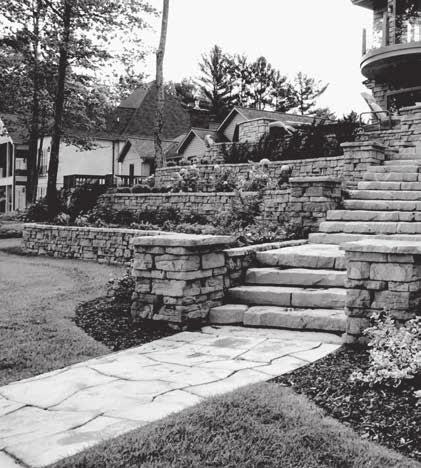
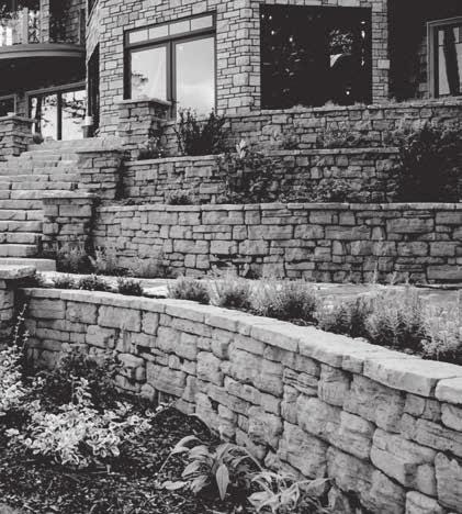
1 C H A N G E Y O U R V I E W


2 Thank you for your interest in Rosetta's premium line hardscape products. You will find that no other engineered system offers the natural beauty, the design flexibility, and the structural stability of the Rosetta system. Rosetta has totally reinvented how natural a concrete hardscape product can look! By accurately capturing the beauty of natural stone, and combining it with the strength and functionality of concrete, Rosetta has truly created an entirely new category of hardscape materials. Rosetta offers a complete line of complementary products that are the most beautiful hardscape materials on the market today. Stone-like seat walls, rustic pillars, beautiful stair risers, strong-yet-naturally inspired retaining walls and more are possible with this amazing collection. 2

3 Table of Contents RETAINING WALL COLLECTION Outcropping...4 Belvedere...6 Dimensional Wall...8 PAVING COLLECTION Grand Flagstone...9 Dimensional Flagstone...10 Rockton...11 STEP & CURB COLLECTION Random Steps...12 Dimensional Steps...12 Stone Edge Curb...12 COPING & CAPS Coping...13 Column Caps...13 Fire Pit...14 RETAINING WALL INSTALLATION GUIDE Installation Instructions...16 Outcropping...20 Belvedere...24 This installation brochure will give you the fundamental knowledge needed to construct stunning, quality retaining walls and landscape step systems that will last for generations. PAVER INSTALLATION GUIDE Installation Instructions...28 Grand Flagstone...29 Dimensional Flagstone...31 Rockton...32 STEP INSTALLATION GUIDE Installation Instructions

4 OUTCROPPING Collection BLOCK DETAILS Stone & Bundling Unit Dimensions L"x H" Units/ Bundle Weight/ Stone lbs. 42" x 12" ± 48" x 12" ± OUTCROPPING PALLET A Pallet weight = ± 4000 lbs. Coverage = 18 ft.² OUTCROPPING PALLET B Pallet weight = ± 4000 lbs. Coverage = 18 ft.² OUTCROPPING PALLET C Pallet weight = ± 4000 lbs. Coverage = 18 ft.² Galvanized Steel hooks are available and required for reinforced walls. Actual weight and colour may vary. 4
5 OUTCROPPING Collection CORNER BLOCK DETAILS Stone & Bundling Unit Dimensions L"x H" Units/ Bundle Weight/ Stone lbs. A CORNER PALLET Pallet weight = ± 4000 lbs. Coverage = 18 ft.² FREESTANDING PALLETS Stone & Bundling Unit Dimensions L"x W"x H" Units/ Bundle Weight/ Stone lbs. Pallet G Pallet G Pallet G OUTCROPPING PALLET G Pallet weight solid = ± 3450 lbs. Coverage = 10.5 ft.² Stone & Bundling Unit Dimensions L"x W"x H" Units/ Bundle Weight/ Stone lbs. Pallet H Pallet H Pallet H OUTCROPPING PALLET H Pallet weight solid = ± 3150 lbs. Coverage = 11 ft.² 5
6 BELVEDERE Collection BLOCK DETAILS Wall Pallet Stone & Bundling Unit Dimensions L"x W"x H" Units/ Bundle Weight/ Stone lbs. Block 1 Block 2 Block 3 Block 4 Block 5 Block 6 Belvedere Collection wall blocks are provided in six basic sizes. The blocks are finished on both the front and back faces of the wall blocks and they are tapered on each side approximately 1" from the front to the back of the block. There are multiple texture patterns for each basic block size to provide a more random look for your finished project. Average block weights of the different texture patterns are shown. Weights of individual blocks may vary. WALL PALLET Pallet weight = ± 2475 lbs. (incl. pallet weight) Coverage = 27 ft.² /Pallet when used in a Retaining Wall and 25 ft.²/pallet when used in a Freestanding Wall Section = 9 ft.² per 2 layers (1 Layer of 6" and 1 Layer of 3") Corner Pallet Stone & Bundling Block 7 CORNER PALLET Pallet weight = ± 1520 lbs. (incl. pallet weight) Coverage = 24 ft.² /Pallet Section = 1.5 ft.² (One 6" piece and one 3" piece) Unit Dimensions L"x W"x H" Units/ Bundle Weight/ Stone lbs. Block 8 The Belvedere Collection contains 2 corner blocks: these blocks are finished on 3 sides and the 4th side is tapered to fit with the other retaining wall blocks. The corner blocks can be used to construct columns, provide a finished end on a freestanding wall, and make 90 corners. There are multiple texture patterns for the faces of both column block sizes, thus providing a more random look for your finished project. Average block weights of the different texture patterns are shown. Weight on individual blocks may vary. 6

7 BELVEDERE Collection COPING DETAILS (caps) Coping blocks are provided in five basic sizes. There are three standard coping blocks which are finished on the front, back, and top faces. The standard coping blocks are tapered approximately 1" on each side from the front to the back of the block. There are also two end units which are finished on the front, back, top, and one of the sides. The other side is tapered approximately 1" from the front to the back of the block. The end units are useful for constructing corners and ends. There are multiple face/texture patterns for each basic block size, providing a more random look for your finished project. Dimensional Coping is also an option for capping the Belvedere Wall (Dimensional coping can be seen on page 15). Average block weights of the different face/texture patterns are shown. Weights of individual blocks may vary. Stone & Bundling Unit Dimensions L"x W"x H" Units/ Bundle Weight/ Stone lbs. Block 9 Block 10 Block 11 Block 12 Block 13 Belvedere Column Cap COPING PALLET Pallet weight = ± 1550 lbs. (incl. pallet weight) Coverage = 66 linear feet/pallet Section = 11 linear feet per 1 Layer 7
 Coverage =25 ft.² /Pallet (Retaining) 25 ft.")
 Section = Sold by the piece Hand-hewn stone texture Consistent dimensions Natural stone texture on five sides Actual weight and volumes may vary.")
8 DIMENSIONAL WALL Collection BLOCK DETAILS Stone & Bundling Unit Dimensions L"x W"x H" Units/ Bundle Weight/ Stone lbs. Straight Wedge DIMENSIONAL WEDGE PALLET DIMENSIONAL STRAIGHT PALLET Pallet weight = ± 2100 lbs. (incl. pallet weight) Coverage =25 ft.² /Pallet (Retaining) 25 ft.²/pallet (Freestanding) Section = Sold by the piece Pallet weight = ± 2000 lbs. (incl. pallet weight) Coverage = 33.3 ft.² /Pallet (Retaining) 26.4 ft.²/pallet (Freestanding) Section = Sold by the piece Hand-hewn stone texture Consistent dimensions Natural stone texture on five sides Actual weight and volumes may vary. Weight shown is based on concrete. RETAINING / FREESTANDING WALL Dimensional Wall Blocks Dimensional Wall Blocks Dimensional Coping (Optional; see pg 15.) Drain Stone Geotextile Fabric Drain Levelling Pad FREESTANDING WALL RETAINING WALL 8
 of each layer shown below are included in each pallet (8 layers total per pallet). Grand Flagstone - 1.")
9 GRAND FLAGSTONE Collection BLOCK DETAILS Outside dimensions of each layer are identical to all other layers, allowing any layer to be used anywhere in the pattern. Two (2) of each layer shown below are included in each pallet (8 layers total per pallet). Grand Flagstone thick Joint Sand Coarse Bedding Sand Compacted Gravel Base Compacted Subbase Materials PACKAGING GRAND FLAGSTONE PALLET 8 Layers per pallet Pallet weight = + 2,000 lbs(incl. pallet) Coverage = 90 sqft/pallet Section = sqft per 1 layer 9

 Jointing Sand between Slabs WALKWAY LAYOUT PATIO LAYOUT Coarse")
10 DIMENSIONAL FLAGSTONE Collection BLOCK DETAILS Dimenional Flagstone Joint Sand Coarse Bedding Sand Compacted Gravel Base Compacted Subbase Material DIMENSIONAL FLAGSTONE PALLET All sizes on every pallet Consistent 2 thickness One Layer = One Pattern 8 layers per pallet Pallet Weight = 2,350 lbs (incl. pallet weight) Coverage = 98 sqft/pallet Section = sqft/layer DIMENSIONAL FLAGSTONE CROSS-SECTION Dimenional Flagstone Slabs (2 thick (45mm) Jointing Sand between Slabs WALKWAY LAYOUT PATIO LAYOUT Coarse Bedding Sand (1 thick (25mm) Compacted Gravel Base (6 thick (150mm) Woven Geotextile (Optional) Compacted Existing Sub-Grade 10
11 ROCKTON Collection BLOCK DETAILS Freestanding Wall Pallet Stone & Bundling Unit Dimensions L"x W"x H" Units/ Bundle Weight/ Stone lbs. Block 1 Block 2 Block 3 Block 4 Rockton Freestanding Wall Blocks are provided in four basic sizes. The blocks are finished on both the front and back faces of the wall blocks and they are tapered on each side approximately 1.5" from the front to the back of the block. There are multiple texture patterns for each basic block size to provide a more random look for your finished project. Average block weights of the different texture patterns are shown. Weights of individual blocks may vary. ROCKTON FREESTANDING WALL PALLET Pallet weight = ± 2500 lbs. (incl. pallet weight) Coverage = ± 20 ft.²/pallet retaining or freestanding wall Section = 7 ft.² per layer ROCKTON CORNER PALLET Pallet weight = ± 2500 lbs. (incl. pallet weight) Coverage = 31.5 ft.²/pallet Section = 1.3 ft.² per piece Corner Pallet Stone & Bundling Unit Dimensions L"x W"x H" Units/ Bundle Weight/ Stone lbs. Block 1 The Rockton Collection contains two corner blocks. These blocks are finished on three sides, and the fourth side is tapered to fit with the other retaining wall and freestanding wall blocks. The corner blocks can be used to construct columns, provide a finished end on a freestanding wall, and make 90 corners. There are multiple texture patterns for the faces of both corner blocks, thus providing a more random look for your finished project. Average block weights of the different texture patterns are shown. Weights of individual blocks may vary. 11
12 RANDOM STEPS STEP & CURB Collection BLOCK DETAILS Stone & Bundling Unit Dimensions L" x H" Rise Weight/ Stone lbs. Step A Step B Step D Step F DIMENSIONAL STEPS RANDOM PALLET Available in 7" rise Pallet of 6 each, 7" rise steps = 4200 lbs. Steps palletized: 2xA, 2xB, 1xD, 1xF DIMENSIONAL PALLET Stone & Bundling Unit Dimensions L"x W"x H" Units/ Bundle Weight/ Stone lbs. Weight/ Pallet lbs. STONE EDGE CURB 12

13 DIMENSIONAL COPING and CAPS BLOCK DETAILS Stone & Bundling Unit Dimensions L"x W"x H" Units/ Bundle Weight/ Stone lbs x x 18 24" Dimensional Coping 18" Dimensional Coping Dimensional Coping End 12.5 x x x x 19 END CAP Dimensional Coping Pallet Overview 6 Layers per pallet 63 Linear Feet/pallet Section = 10.5 Linear Feet per 1 Layer Stone & Bundling Unit Dimensions L"x W"x H" Units/ Bundle Weight/ Stone lbs. Belvedere Column Cap 13

14 ROUND FIRE PIT FIRE PIT Kits DETAILS 14 Round Fire Pit Pallet: Weight: ± 1320 lbs. BLOCK LAYOUT PATTERN BLOCK KEY 17 x 6 11 x 6 6 x6 17 x 3 11 x 3 6 x 3 C AP SQUARE FIRE PIT 12 Square Fire Pit Pallet: Weight: ± 1130 lbs. INSTRUCTIONS: For Both Round & Square Fire Pit Kits 44 x 44 SQUARE 1. Familiarize yourself with the construction details shown on this page. 2. Mark out the location for your fire pit. Note the dimensions shown are nominal so mark in area slightly larger than shown. 3. Excavate for drainstone base (approx. 6"). 4. Fill excavate for drainstone, level, and compact. 5. Place and center steel ring on prepared base. 6. Place blocks per the pattern. (For Round Kit, keep Blocks 1.5" off steel ring). 7. WARNING: DO NOT place Rosetta Fire Pits directly on Rosetta Flagstone product or any comparable concrete product or slab as high heat can adversely affect the integrity of the product. ADDITIONAL INSTRUCTIONS FOR ROUND FIRE PIT ONLY. 8. After placing blocks around the ring, adjust the blocks in or out to make the circle close and fit tight. If the blocks do not close the circle, move all blocks slightly in. If the blocks seem too long, move the blocks slightly out. 9. Place caps in circle around fire pit. Adjust the caps in or out to make them fit tightly together. 10. NOTE: Not suitable for large fires. Fire size should not allow flame to contact Caps on Round Fire Pit. ** Fire Pit metal insert may vary from that pictured above. ** 14
15 15
16 INSTALLATION Instructions RETAINING WALL (general) ROSETTA RETAINING WALL INSTALLATION NOTES Thank you for your interest in installing a quality retaining wall system by Rosetta Hardscapes. The following guide describes proper installation techniques for the Rosetta Outcropping, Belvedere, Dimensional, and Rockton Wall systems. This installation guide will help cover the basic steps required to construct a beautiful, structurally-sound retaining wall. For optimal color blending, you must mix and install products from several different pallets simultaneously. PRE-CONSTRUCTION CHECKLIST: Before you start construction, take the time to complete the necessary planning and preparation. This process will keep your project running efficiently and will aid in completing a quality installation. Make sure to address the following: SAFETY Your safety program should address items such as personal protective equipment, maintaining safe slopes and excavations, fall protection, rigging and lifting, as well as any other relevant safety precautions. ENGINEERING AND PERMITS Obtain the necessary engineering designs and permits for your project. The soils for foundation and wall backfill should be properly evaluated by a trained professional. Unsuitable soils should be removed and replaced as recommended. Note: This installation guide is intended to supplement a detailed, site-specific wall design prepared by a Professional Engineer. The construction documents for your project supersede any recommendations presented here. REVIEW THE PROJECT PLANS Take the time to review and understand the project plans and specifications. Make sure you understand the detailed design for the project before starting construction. A pre-construction meeting with the wall designer, construction inspector, wall contractor, and owner or representative is recommended. Do not be afraid to ask questions. CONSTRUCTION PLANNING Develop a plan to coordinate construction activities such as material delivery/storage, equipment access, etc., on your site. Make sure your plan specifically addresses how to control surface water during construction. UTILITY LOCATION Make sure to have underground utilities located and marked on the ground before starting any construction. Call 811 or go online to to schedule utility marking for your project site. MATERIAL STAGING Store retaining wall blocks in a location close to the proposed wall. Blocks should be kept clean and mud-free. Blocks should also be stored in a location which will minimize the amount of handling on the project site. Store geogrid in a clean, dry location close to the proposed wall site. Keep the geogrid covered or in the shade until installation to avoid exposure to direct sunlight. EQUIPMENT Make sure you have the proper equipment to handle retaining wall blocks and pallets on the construction site. (Note: A specially-designed Rosetta Lifting Device is required for the installation of Rosetta Outcropping blocks). Hand-operated equipment used in wall construction should include shovels, a 2'(600 mm) level, a 4'(1.2 m) level, brooms, hammers, chisels, tape measures, string, spray paint, a laser level, pry bars, concrete saws, and a walk-behind vibratory plate compactor capable of delivering a minimum of 2000 lbs. (9 kn) centrifugal force. Personal protective equipment should include appropriate clothing, steel toe boots, eye protection, hardhats, gloves, hearing protection, fall protection, rigging, and other items as necessary to ensure a safe working environment. 16

. This will provide 6\" (150 mm) for the leveling pad and 6\" (150 mm) of minimum bury of the blocks.")
17 INSTALLATION Instructions RETAINING WALL (general) BASE PREPARATION Proper base preparation is a critical element in the construction of your retaining wall. Not only is it important to provide a stable foundation for the wall, but a properly-prepared base will greatly increase the speed and efficiency of your wall installation. Proper base preparation starts with the subgrade soils (soils below the leveling pad). Existing soils must be removed to the bottom of the leveling pad elevation for the retaining wall. A typical wall requires excavation of at least 12" (300 mm). This will provide 6" (150 mm) for the leveling pad and 6" (150 mm) of minimum bury of the blocks. (Note: the excavation and bury depth will vary by product type and design. Please see project plans or product-specific information for further information). At a minimum, all topsoil, organic, unsuitable soils should be removed from below the wall. The minimum width of the leveling pad should be 18" (465 mm) wider than the width of the block. This will provide 6" (150 mm) in front of and 12" (300 mm) behind the bottom block. Once excavated, the subgrade soil should be compacted to a minimum of 95% maximum density as determined by a Standard Proctor test (ASTM D698). At this point the soil should be firm, dry, and free of topsoil debris, stones, roots, etc. Consult a soils engineer if in doubt. Any unsuitable material must be excavated and replaced as directed by the engineer. LEVELING PAD Base preparation continues with proper leveling pad construction. An open-graded (free-draining) crushed stone leveling pad is typically used for retaining walls. Walls can also be designed with a dense-graded crushed stone or concrete leveling pad. The choice of which type of leveling pad to use is made by the wall designer and depends on several factors including the bearing capacity of the native soil, location of the drain outlet, conditions at the base of the wall, and any other special considerations for the wall. The leveling pad material should be placed and compacted to provide a uniform, level foundation on which to construct the retaining wall. Proper elevation can be established with a laser level or transit. Check for level both parallel and perpendicular to the wall. Place and compact leveling pad material as specified in the wall design. If crushed stone is used, place the stone in uniform loose lifts at a maximum of 6" (150 mm) thick. Lift sizes are relative to the size of the compactor being used. Compact the stone with a minimum of 3 passes with a 24" (600 mm) wide, walk-behind vibrating plate compactor. Note: DO NOT place a thin layer of sand between the leveling pad and bottom block. This layer will reduce the sliding resistance between the leveling pad and the bottom block, as well as reduce the drainage capacity of the foundation stone. DRAIN A drain is installed in the lowest part of the open-graded (free-draining) stone behind the retaining wall. If an open-graded crushed stone leveling pad is used, the drain is installed on the bottom of the crushed stone leveling pad. If a dense graded crushed stone leveling pad is used, the drain is installed immediately on top of the dense graded stone. Typically, a 4" (100 mm) diameter perforated "sock" pipe is used. Daylight the drain pipe at the ends and/or through the face of the wall every 50' to allow for drainage. The pipe can also outlet into a nearby drainage ditch or catch basin. Because water can flow both ways through the drain pipe, connection to a catch basin or active storm sewer should only be made under the direction of a Professional Engineer. 17

18 INSTALLATION Instructions RETAINING WALL (general) SETTING THE BOTTOM COURSE OF BLOCKS Proper placement of the bottom course of wall stones is critical in determining the overall appearance and integrity of the finished project. Take extra time on this step and the rest of the project will go smoothly. At this point, you need to determine the best point of origin for the wall. If you have a fixed point, such as a building corner or a 90 corner, you will want to start the wall from that point and work your way out. This will minimize cutting of blocks. If there are no fixed points, start the wall at the lowest design elevation, as it is easier to step the base up than it is to step the base down. Properly mark the location of the retaining wall. A string line or offset stakes are typically used to establish horizontal and vertical alignment. Where applicable, remove the bottom lip from the back edge of the blocks with a hammer and chisel (bottom course of blocks only) so the blocks will lie flat on the leveling pad. Place a complete row of blocks on the prepared leveling pad. Blocks should be placed tight together. Check all blocks for level from front to back and side to side as they are placed. Place and compact backfill in front of the bottom row of blocks to help hold them in place. Compaction should be to 95% maximum density as determined by a Standard Proctor test (AST D698). Place open-graded crushed stone in the cores of the blocks, between the blocks, and at least 12" (300 mm) behind the wall. A stone meeting the gradation requirements of ASTM No. 57 with no material passing the No. 200 sieve is preferred. Place the stone in uniform loose lifts a maximum of 8" (200 mm) thick. Fully consolidate the stone. Carefully hand tamp the stone within 12" (300 mm) of the blocks. Place non-woven geotextile fabric between the drainstone and the remaining backfill material if specified. Backfill behind the drainstone with material as specified in the project design. Place the material in loose lifts as specified, but not to exceed 8" (200 mm) maximum. Granular backfill must be compacted to a minimum of 95% maximum density as determined by a Standard Proctor test (ASTM D698). Do not use any organic, topsoil, frozen, soft, wet, or loose soils when backfilling the wall. Re-check all units for level and alignment and sweep the top of each course of blocks clean before starting construction of the next course. SETTING THE UPPER COURSES OF BLOCKS Placing the next course of blocks is similar to placing the first course. Blocks should be placed to establish a running bond pattern (Rosetta or Dimensional Collections) or to follow an irregular pattern (Rosetta Outcropping and Belvedere Collections). Blocks should be installed with their sides pushed tight. Push blocks from Rosetta Outcropping Collection forward until the lip on the back of the block comes in full contact with the blocks below. Make sure that no stones get caught or wedged between the lip and the back of the blocks below. Walls without the lip on the bottom (Rosetta, Belvedere, and Dimensional Collections) should not be stacked exactly vertical. Instead, they should be set back approximately 1/2" for every 6" of wall height to provide for a wall batter. ROSETTA OUTCROPPING: Place a layer of non-woven geotextile fabric directly behind the blocks. This will keep materials from eroding through the small voids between the blocks. Place geogrid reinforcing behind the wall as specified in the project documents. See Geogrid Installation information in the next section for further details. Place and compact open-graded crushed stone in the cores of the blocks, between the blocks, and at least 12" (300 mm) behind the wall following the procedure used for the bottom course of blocks. Place non-woven geotextile fabric between the drainstone and the remaining backfill material if specified. Place and compact backfill behind the drainstone following the procedure used for the bottom course of blocks. Re-check all units for level and alignment and sweep the top of each course of blocks clean before starting construction of the next course. REPEAT THESE STEPS WITH EACH COURSE OF BLOCKS TO THE TOP OF THE WALL. 18

19 INSTALLATION Instructions RETAINING WALL (general) GEOGRID INSTALLATION The stability of reinforced soil walls relies on the interaction between geogrid reinforcement, soil in the reinforced zone, and the retaining blocks. It is very important that the reinforced soil walls be constructed as per the detailed design prepared by a Professional Engineer. Make sure you are using the proper type and strength of geogrid listed in the design. The geogrid layers need be placed at the proper elevations and to the proper distances into the reinforced soil zone detailed in the design. It is also critical to use the appropriate backfill soil material in the reinforced soil zone. Construct the wall up to the elevation of the geogrid layer shown in the design. Place geogrid layers as shown in the project details extending into the reinforced soil zone to the design length. Geogrid must be installed with the strong direction (roll direction) into the reinforced soil zone and not parallel to the wall. Geogrid must be placed in a continuous sheet throughout its length from the connection at the blocks to the back of the reinforced zone. Do not splice or overlap the geogrid. For all retaining wall products except the Rosetta Outcropping Collection use the next layer of blocks to secure the front end of the geogrid. Make sure the geogrid is as close as possible to the front face of the wall without being visible. Pull the geogrid taut to eliminate any folds and pretension the geogrid. Pin or secure the back edge of the geogrid before placing the reinforced fill. FINISHING THE TOP OF THE WALL Completing a few simple tasks near the end of the project will ensure that the wall will function properly and look good for years to come. Grade the top of the wall in such a way that surface water runs off away from the wall. Never leave the top of the wall graded where surface water will pond behind the wall, or saturate the backfill soils. Place a layer of non-woven geotextile fabric over the top of the drainstone at the back of the wall. This will keep topsoil from migrating into the drainstone and causing problems. If required, place the coping layer on the top of the wall. The coping blocks should be placed towards the front edge of the wall blocks and should sit securely on top without tipping forward under their own weight. The coping layer should be carefully adhered with a concrete adhesive specifically formulated for segmental concrete block wall construction. MORE INFORMATION Refer to product-specific Typical Construction Details for specific applications and construction practices such as chimney drain construction, fence installation, corner construction, drain placement, curve construction, and other details. Typical allowable construction tolerance at the wall face is 1" in 10' (1:120) in the vertical and horizontal directions, and a rotation tolerance of 2 from wall batter. Once you commence working, continue without interruption or delays. This will help expedite construction and minimize the time the excavation is open. If at any time groundwater seepage is observed along the exposed excavation behind the retaining wall, contact the wall designer immediately to determine the corrective action needed. The construction site should be graded and maintained to direct surface water runoff away from the retaining wall throughout the entire construction process. If there is a rain event with surface water runoff producing erosion or scour near the retaining wall, contact the wall designer immediately to determine the corrective action needed. 19
20 RETAINING WALL TYPICAL GRAVITY WALL SECTION This page shows typical construction details for Gravity walls. These drawings are representative of the major components required in wall construction. Specific details, including geotextile reinforcement layers, drainage details, soil requirements, etc., shall be per professionally-engineered design for wall. For more cross-section and design options, please visit and click on "engineering." INSTALLATION Instructions OUTCROPPING NOTE: Block size and placement shown are for reference only. Individual Rosetta blocks will vary with installation pattern. Actual design must be performed by a licensed engineer. FREESTANDING WALL CONCEPTUAL GROUTED WALL SECTION Block size and placement shown are for reference only. Individual Rosetta blocks will vary with installation pattern. TYPICAL FREESTANDING WALL This page shows typical construction details for Outcropping Freestanding walls. These drawings are representative of major components required in wall construction. Specific details including drainage details, soil requirements, etc. must be based upon professionally-engineered per-project designs for wall. 20

21 INSTALLATION Instructions OUTCROPPING RETAINING & FREESTANDING WALLS Outcropping Notes for Installations Requiring Geogrid Please visit for detailed cross-sections of geogrid reinforced Outcropping walls. For Rosetta Outcropping installations, do not overlap geogrid over top of blocks. Instead, run the geogrid directly up to the back of the blocks. In addition to this reinforcement, a Paraweb strap must be installed through each lifting hook in the back of the Outcropping blocks. Please see standard details for Reinforced Outcropping Walls for further information. Place and compact drainstone and reinforced fill following the procedure used to set the bottom and upper courses of blocks. It is important to place and compact stone and reinforced fill starting at the back of the retaining blocks and extending into the reinforced soil zone. This will help eliminate "bunching" of the geogrid reinforcement. Reinforced zone fill material is typically a sand or gravel with less than 5% "fines" (material passing the No. 200 sieve). This material is usually classified as a GW, GP, SW, or SP. It is very important that you only use the fill material specified in your project design drawings and specifications. Place retained soil immediately between the reinforced soil zone and the back of the excavation. Material should be placed in loose lifts of 8" (200 mm) maximum and compacted to 95% maximum density as determined by a Standard Proctor test (ASTM D698). Bring the reinforced and retained soil up to grade at the same time. At no time should the elevation of the reinforced soil be more than 1 block higher than the retained soil. Tracked construction equipment should not be used directly on the geogrid. A minimum of 6" (150 mm) of fill is required between tracked equipment and geogrid to prevent damage to the grid. Rubber-tired equipment may pass over the geogrid when traveling at low speeds of 5 mph (8 km/h) or less. Avoid any sudden stopping or turning of construction equipment in the reinforced fill zone to prevent moving or damaging the geogrid layers. Follow geogrid manufacturer's requirements, including requirements for vertical separation and overlap of geogrid. For All Installations Never stack blocks more than one course above grade of backfill. Outcropping Layout Notes One of the unique features of the Rosetta Outcropping system is multiple block heights. To provide a uniform wall batter with multiple height blocks, the setback of the blocks varies proportionally with the block height. This setback in blocks is achieved with shear heels which are cast into the Rosetta blocks. For a 6" high block, the shear heels are 3" deep (1 3"). For a 24" high block, the shear heels are 6" deep (2 3"). Outcropping Lifting Device To ensure proper wall alignment and to account for the multiple height blocks and varying setbacks, you have to adjust the bottom row of blocks based on their height. Set up a traditional string line for the back of the wall, then offset the blocks as per the following figure. Back of Wall String Line(top view) 4.5 (114mm) 3 (76mm) 0 (0mm) 6 HIGH BLOCKS (114 mm) from string line 12 HIGH BLOCKS (76 mm) from string line 18 HIGH BLOCKS (38 mm) from string line 24 HIGH BLOCKS Set back of block 21

.")

 CURVE If you are constructing an inside (concave) curve, the wall batter will cause the block higher in the wall to have a longer radius around the curve than the lower blocks.")
22 INSTALLATION Instructions OUTCROPPING CURVES Rosetta Blocks have shear heels to help with wall integrity and provide a setback from lower blocks in the wall. This causes the wall to batter back. The batter is important to the engineering design of the wall, and it must be accounted for during construction of a curved wall section. OUTSIDE (CONVEX) CURVE If you are constructing an outside (convex) curve, the wall batter will cause the blocks higher in the wall to have a shorter radius around the curve than lower blocks. This will cause the higher blocks to "grow" in the wall layout pattern. (This is similar in concept to the inside lane of a race track that is shorter than the outside lane). The result is a potential overlap between some of the blocks in the wall. The best way to deal with this overlap is to saw cut the end of the smaller block, which allows the other blocks to fit tightly together. This will properly engage all of the shear heels. Saw cutting here is typically made on an angle to match the taper on the block you are abutting. INSIDE (CONCAVE) CURVE If you are constructing an inside (concave) curve, the wall batter will cause the block higher in the wall to have a longer radius around the curve than the lower blocks. The important step when constructing an inside curve is to keep all blocks fitted tightly together. In most cases, the blocks will touch somewhere along the sides of the blocks, not at the back of the blocks. If needed, you can trim the ends off of some blocks to prevent gaps from opening up between blocks. When constructing a curve with a short radius, voids may form at the back of the wall where to blocks meet. If this happens, simply fill the void areas with filter fabric and drainstone. 22
23 INSTALLATION Instructions OUTCROPPING PATTERNS Please note that the length dimensions shown for Rosetta blocks are rounded for reference. The actual length of the constructed wall will vary slightly from the pattern dimensions shown. Each pattern is made up of (2) A Pallets, (2) B Pallets, and (1) C Pallet. 2 X 45 WALL SECTION SHOWN: 4.5 x 1 3 x0.5 4 x0.5 5 x 1 2 x0.5 4 x 1 2 x0.5 4 x0.5 3 x0.5 4 x 1 6 x 1 4 x x x 1 5 x 1 3 x0.5 2 x0.5 5 x x0.5 3 x1 4.5 x x 1 6 x x 1 3 X 30 WALL SECTION SHOWN: 5 x x 1 6 x x 1 4 x x 1 5 x x 1 2 x0.5 4 x0.5 4 x 1 2 x0.5 3 x1 3 x1 3 x0.5 2 x0.5 3 x0.5 4 x0.5 3 x x x 1 5 x x 1 4 x 1 4 X 22.5 WALL SECTION SHOWN: 5 X 18 WALL SECTION SHOWN: 4 x x 1 2 x0.5 3 x x 1 6 x 1 5 x 1 2 x0.5 3 x0.5 2 x x 1 3 x0.5 4 x 1 3 x1 4 x 1 5 x x x 1 6 x 1 4 x0.5 3 x1 4 x 2 6 x 1 5 x 1 4 x0.5 3 x0.5 3 x0.5 4 x0.5 3 x1 4.5 x 1 4 x0.5 2 x0.5 2 x0.5 3 x1 5 x x x x 1 5 x x x 1 3 x0.5 2 x0.5 4 x 2 5 x x x 1 Rosetta has 2 corner blocks to help make a 90 corner in the wall. The corner blocks are 4-sided, and can be installed with alternating faces exposed to maintain a more random look. The size of the corner blocks have been chosen to account for the wall batter in both directions. Two 6" high corner blocks are typically stacked on top of each other and placed on top of 12" high corner blocks that are intended to be stepped back 3" in both directions. In a few areas, you may need to trim a small part of the corner blocks near the back of the wall to avoid interference with the shear heels on adjacent blocks. See the sample pattern shown here, which details how to make a 90 corner with (4) A Pallets, (4) B Pallets, (2) C Pallets, (3) 12" high corner blocks, and (4) 6" high corner blocks. 90 WALL CORNER END OF BLOCK 27 x39 x6 CORNER END OF BLOCK 30 X 48 X 12 CORNER END OF BLOCK 27 x39 x6 CORNER END OF BLOCK 5 x 1 3 x x 1 4 x0.5 5 x x0.5 4 x0.5 2 x0.5 4 x 1 3 x1 6 x 1 4 x 2 6 x x 1 4 x 1 2 x0.5 2 x x x 1 5 x x x 1 3 x0.5 3 x0.5 5 x x x x 1 5 x 1 6 x 1 3 x1 4 x 1 2 x0.5 3 x0.5 3 x1 4.5 x 1 5 x x1 4 x x x48 x12 CORNER 3 x0.5 END OF BLOCK 2 x x39 x6 CORNER 3.5 x 1 END OF BLOCK 3 x x39 x6 CORNER 4 x0.5 END OF BLOCK 4 x 1 30 x48 x12 CORNER 90 WALL CORNER
24 INSTALLATION Instructions BELVEDERE RETAINING WALL TYPICAL RETAINING WALL CONSTRUCTION DETAILS This page shows typical construction details for Belvedere retaining walls. These drawings are representative of major components required in wall construction. Specific details including geotextile reinforcement layers, drainage details, soil requirements, etc., shall be per engineered design for wall. This drawing is for reference only. Final design for construction must be prepared by a registered Professional Engineer using the actual conditions of the proposed site. Final wall design must address both internal and external drainage and shall be evaluated by the Professional Engineer who is responsible for the wall design. Block size and placement shown are for reference only. Individual Belvedere blocks will vary with installation pattern. TYPICAL FREESTANDING WALL CONSTRUCTION DETAILS FREESTANDING WALL Belvedere freestanding walls are intended to be low walls (24" or lower) used in a garden or patio setting. Taller walls i.e. walls intended to act as railing or barriers, walls constructed in other settings, or walls subject to applied loads will require project-specific engineering. Block Orientation (top view) This drawing is for reference only. Final design for construction for walls subject to any loading must be prepared by a registered Professional Engineer. Block size and placement shown for reference only. Individual Belvedere blocks will vary with installation pattern. 24
25 INSTALLATION Instructions BELVEDERE CURVES This page shows typical construction details for making curved retaining walls with Belvedere blocks. The taper on the side of the blocks allow for construction of a wide range of curves in both retaining and freestanding walls. OUTSIDE CURVE INSIDE CURVE Note: 1. These details show curved retaining walls. 2. Minimum radius curves are shown which can be constructed without saw cutting a significant number of blocks. Larger radius curves can be created by leaving a larger gap between blocks on the backside of the wall. The gaps must be filled with drainstone. 3. When retaining walls are constructed with batter, the radius on the outside curves becomes smaller with each course due to the block setback. For proper construction, the radius of the bottom course must be larger than the minimum radius so that upper courses will have sufficient room for construction. 4. When retaining walls are constructed with a batter, the radius on the inside curves becomes larger with each course due to the block setback. CURVED FREESTANDING WALLS Curved freestanding walls can also be built. Typically, the blocks have to be field-adjusted to make the desired curve. Front and back faces will alternate and blocks trimmed as needed to provide a tight fit between blocks with no gaps on either side of the freestanding wall. PLANTER/ TREE RING Note: Walls are shown without batter for clarity. Blocks in a retaining wall should be adjusted slightly in place and trimmed as needed to allow wall construction with proper batter. 25
26 INSTALLATION Instructions BELVEDERE PILLARS PILLAR CONSTRUCTION DETAILS This page shows typical construction details for Belvedere pillars. Pillars make nice ends to Freestanding walls, formal stair openings, stand-alone monuments, and other areas to enhance your Belvedere project. The basic steps of pillar construction are shown here. Feel free to expand on these ideas and bring your own creativity into creating a custom project. STEP ONE Place (4) 3" or 6" high corner blocks with the taper facing into the center of the pillar. STEP TWO Place the second row of (4) of the corner blocks with the taper facing into the center of the pillar. Typically, if the first row is built with 6" corner blocks, the second row is built with 3" corner blocks. STEP THREE Continuous with subsequent rows to the desired pillar height. One pallet of corner blocks will make a 24" x 24" x 36" high column. STEP 4 Place a column cap to finish the pillar. The column cap can be cored as needed for installation of a light. This example shows a freestanding wall with pillars on each end. The wall can either be constructed flush with the pillars, or blocks trimmed to interlock the end of the wall with the pillar. OUTSIDE CORNER CORNERS INSIDE CORNER CORNER CONSTRUCTION DETAILS This page shows typical construction details for making 90 corners Belvedere blocks. Some basic concepts are shown here. Plan to take some time to properly work corners into the larger retaining and freestanding wall patterns. INTERLOCKING CORNER Place block in an overlapping, interlocking pattern at corner for added wall stability. Note: Walls are shown without batter for clarity. Blocks in a retaining wall should be adjusted slightly in place and trimmed as needed to allow wall construction with proper batter. 26
27 INSTALLATION Instructions BELVEDERE PATTERNS NOTE: The blocks shown below are labeled, for example, 4F would indicate the front (or longer) face of block 4, and 2B would indicate the back (or shorter) face of block 2. NOTE: These patterns are NOT required and are presented for reference only. They are most useful for long, straight retaining walls. 12 High Wall 12 High x 13-6 Wall Section Shown = 13.5 sqft (1/2 Wall Pallet) 18 High Wall 18 High x 18-0 Wall Section Shown = 27.0 sqft (1 Wall Pallet) 24 High Wall 24 High x 16-0 Wall Section Shown = 32 sqft (Approx. 1.2 Wall Pallet) NOTE: RETAINING WALLS are typically constructed with the front face of the block exposed. The v-shaped notches which appear on the back of wall between adjacent blocks must be filled with drainstone. FREESTANDING WALL PATTERNS Block Orientation (Top View) Face of Wall Back of Wall 24 Pattern A Wall Section Shown = sqft (Approx. 1 Wall Pallet) 24 Pattern B Wall Section Shown = sqft (Approx. 1 Wall Pallet) 24 High Vertical End - Left Wall section Shown = sqft (1/2 Wall Pallet) Note: Vertical End Jogs in and out approximately 1 between blocks 24 High Vertical End - Right Wall section Shown = sqft (1/2 Wall Pallet) Note: Vertical End Jogs in and out approximately 1 between blocks 27 Block Orientation Face of Wall Back of Wall
28 INSTALLATION Instructions FLAGSTONE & PAVERS (general) FLAGSTONE AND PAVER INSTALLATION GUIDE Thank you for your interest in installing Rosetta paving products. You will find that these products truly combine the look of natural stone with the efficiency and consistency of concrete pavers. The following guide lays out proper installation techniques for Rosetta Grand and Dimensional Flagstone slabs as well as for Old Mission Pavers. For optimal color blending you must mix and install products from several different pallets simultaneously. We hope this provides helpful tips for a fast, enjoyable installation. SAFETY Make safety a top priority when installing Rosetta paving products. Before starting your project, be sure to address the following points: 1. Contact your local utility marking service prior to making any excavation. Be sure to follow all governmental safety regulations. 2. Always wear the appropriate personal protective equipment (PPE) including gloves, steel toed boots, safety glasses, hearing protection, and any other needed safety gear. 3. Flagstone slabs are heavy. Follow proper lifting techniques to avoid back injury. Also, use two people to set larger pieces. PROJECT PLANNING The first step in installing Rosetta paving products is to plan your project. Paver layout and placement is important to ensure a functional and good-looking installation. Remember, Rosetta flagstone products are suitable for pedestrian loading only (patios, walkways, etc.) and will not support the load of a vehicle. Old Mission Pavers are suitable for vehicular loading. EXCAVATION AND BASE PREPARATION Once you are ready to start construction, you will need to lay out the project area. Mark out the area of the installation with marking paint. Mark a second line 12" (305 mm) outside of the first line that indicates the area to be excavated. This over-excavation will allow for proper base installation. Excavate to the required depth and grade for the installation of the specific Rosetta paving product you are installing (see cross-sections for minimum recommended excavation depths). Once the excavation depth has been established, compact the subgrade well using a plate tamper. At this point, Rosetta Hardscapes recommends laying a woven geotextile down before applying any granular base materials. PERMEABLE INSTALLATIONS: Unless specified, avoid compaction of existing subgrade soils if installing a permeable pavement. PLACE THE COMPACTED GRAVEL BASE For standard paver and flagstone installations, begin by spreading half of granular base material in the excavation. (Note: lifts should not exceed 6" (150 mm) in thickness). Compact this first lift to 98% Standard Proctor density using a plate tamper and adding water as needed. Add the second lift of granular material and compact it in the same manner as the first. For permeable paver installations, install open-graded sub-base and base course material as specified in the project drawings. KEY POINT: When installing granular base materials, be sure to consider proper grades to prevent water from standing on the surface and make sure that water is directed away from building structures. PAVER INSTALLATION Bedding material requirements and paver installation vary by product type. Please see the following product-specific installation instructions and tips for more details on paver installation. 28
29 INSTALLATION Instructions GRAND FLAGSTONE GRAND FLAGSTONE INSTALLATION BEDDING SAND INSTALLATION: Using screed rails on the compacted granular base, apply bedding sand at a maximum thickness of 1" (25 mm). By using a screed board along the top of the screed rails, the bedding sand will level evenly. Bedding sand should be compacted since Grand Flagstone slabs should not be compacted after installation. FLAGSTONE INSTALLATION: 1. Begin by laying the individual pieces of Grand Flagstone on the screeded bedding material according to your detailed project plan. 2. Separate individual pieces approximately 3/8" (10 mm) from each other. When units are set with a 3/8" gap, a full pallet will produce 90 ft.² (8.36 m²) coverage. 3. Cut units as needed to finish edges. NOTE: To ensure proper colour distribution, mix layers from several bundles at one time. JOINT SAND INSTALLATION: Once the flagstone pieces are installed, fill all joints with jointing sand suitable for large joints. Sweep the sand into the joints between flagstones until the joints are completely filled. Follow the jointing sand manufacturer's recommendations for wetting the sand. You may need to repeat this process with more dry sand in a few days to completely fill the joints between individual slabs. CAUTION: Grand Flagstone slabs should not be compacted after installation. OTHER CONSIDERATIONS SEALING: You may want to apply a sealer to protect the flagstone slabs from spills and stains. Always use a high quality sealer specifically formulated for wet-cast concrete. ** NOT SUITABLE FOR VEHICULAR TRAFFIC ** Typical Cross-Section Grand Flagstone Slabs (1.75 thick (45mm) Jointing Sand between Slabs Coarse Bedding Sand (1 thick (25mm) Compacted Gravel Base (6 thick (150mm) Woven Geotextile (Optional) Compacted Existing Sub-Grade Straight Walkway Installation Leave Jagged Edge or Trim to Provide Smooth Edge (Optional) Placing Grand Flagstone + (TYPICAL) 29
30 INSTALLATION Instructions GRAND FLAGSTONE INTERLOCKING LAYERS: Grand Flagstone has been designed so that each layer of slabs on pallet is an interlocking set. Each interlocking set, or layer, of slabs has been designed to interlock with all other layers. COMMON POINTS FOR INTERLOCKING LAYERS LAYOUT ORIENTATION: Layout orientation is important with Grand Flagstone. Due to the nature of the interlocking sets slabs, there are long, unbroken joints between rows. Often, the irregular nature of the Grand Flagstone limits how noticeable these unbroken joints are in the finished project. However, the lines become slightly more noticeable when you are looking parallel to the unbroken joints than when you are looking at them on an angle. To limit this effect, Grand Flagstone layers should be laid at a 45 angle from the most common viewing angle. This viewing angle would most likely be a patio entrance or step location. INCORRE C T VIEW Main Walkway Long, Unbroken Lines Caused by Seam Between Layers CORRE CT VIEW PROPERLY PLACED INTERLOCKING LAYERS Main Walkway Long, Unbroken Lines Caused by Seam Between Layers Oriented at 45 Angle from Main View Long, Unbroken Lines Caused by Seam Between Layers Oriented as close to 45 Angle from Secondary View as Possible PROCEDURE FOR INSTALLING CRACKED PIECES: Individual pieces of Grand Flagstone can crack either during delivery to the job or during on-site handling prior to placement. Typically less than 5% of the pieces will crack. There are two methods to deal with cracked pieces. The first method is to use the cracked pieces to fill in around the edges of the project where there is always a need for small pieces. The second method is to use the cracked pieces to enhance the layout pattern. Since Grand Flagstone is designed to create an irregular flagstone walking surface, an extra crack simply provides another joint line in the Grand Flagstone pattern. Place the cracked pieces next to each other with a 3/8" (10 mm) joint between them. The joint is filled with polymeric jointing sand just like all other joints. If necessary, the cracked pieces may need to be trimmed to create a smooth edge or provide a larger joint to match all the other joints in your project. 30 INSTALLING CRACKED PIECES + / 1. TRIM BROKEN EDGES IF NEEDED 2. INSTALL PIECES WITH TYPICAL 3/8 (10MM JOINT)
31 DIMENSIONAL FLAGSTONE INSTALLATION BEDDING SAND INSTALLATION: Using screed rails on the compacted granular base, apply bedding sand at a maximum thickness of 1 (25mm). By using a screed board along the top of the screed rails, the bedding sand will level evenly. Bedding sand should be compacted since Dimensional Flagstone slabs should not be compacted after installation. FLAGSTONE INSTALLATION: 1. Begin by laying the individual pieces of Dimensional Flagstone on the screeded bedding material according to your detailed project plan. 2. Push flagstone slabs directly together so the bottom edges butt tight. There is no need to space the slabs to create the neces sary joint. Joint is pre-set in the unit. 3. Cut units as needed to finish edges of installation. NOTE: To ensure proper color distribution, mix layers from several bundles at one time. JOINT SAND INSTALLATION: Once the flagstone pieces are installed, fill all joints with jointing sand suitable for large joints. Sweep the sand into the joints between flagstones until the joints are completely filled. Follow the jointing sand manufacturer s recommendations for wetting the sand. You may need to repeat this process with more dry sand in a few days to completely fill the joints between individual slabs. CAUTION: Dimensional Flagstone slabs should not be compacted after installation. OTHER CONSIDERATIONS: DIMENSIONAL FLAGSTONE CROSS-SECTION Dimenional Flagstone Slabs (2 thick (45mm) Jointing Sand between Slabs INSTALLATION Instructions DIMENSIONAL FLAGSTONE You may want to apply a sealer to protect the flagstone slabs from spills and stains. Always use a high quality sealer specifically formulated for wet-cast concrete. ** NOT SUITABLE FOR VEHICULAR TRAFFIC ** PATIO LAYOUT Coarse Bedding Sand (1 thick (25mm) Compacted Gravel Base (6 thick (150mm) Woven Geotextile (Optional) Compacted Existing Sub-Grade WALKWAY LAYOUT 31
32 INSTALLATION Instructions ROCKTON FREESTANDING WALL TYPICAL RETAINING WALL CONSTRUCTION DETAILS This page shows typical construction details for Rockton retaining walls. These drawings are representative of major components required in wall construction. Specific details including geotextile reinforcement layers, drainage details, soil requirements, etc. shall be per engineered design for wall. This drawing is for reference only Final design for construction must be prepared by a registered rofessional Engineer using the actual conditions of the proposed site. Final wall design must address both internal and external drainage and shall be evaluated by the Professional Engineer who is responsible for the wall design. PILLARS Rockton pillars can be constructed utilizing 1 full pallet of Rockton Corner Blocks. A 34 Column Cap can be utilized to finish the pillar. The column cap can be cored as needed to accommodate the installation of a lamp. CURVED WALLS The taper side of Rockton blocks allow for construction of a wide range of curves in both retaining and freestanding walls. 1. Minimum radius curves shown above can be constructed without saw-cutting a significant number of blocks. Larger radius curves can be created by leaving a larger gap between blocks on the back side of the wall. The gaps must be filled with drainstone. 2. When retaining walls are constructed with batter, the radius on outside curves become smaller with each course due to the block setback. For proper construction, the radius of the bottom course must be larger than the minimum radius so upper courses will have sufficient room for construction. 3. When retaining walls are constructed with batter, the radius on inside curves becomes larger with each course due to the block setback. 32
33 INSTALLATION Instructions STEPS STEP INSTALLATION BEGIN THE STEP INSTALLATION PROCESS by measuring the total rise required and calculating the number of steps to be used. Each step has a 7 rise, but should be sloped approximately 1/2 such that the back of the step is higher than the front of the step. This slope will facilitate surface water drainage. With appropriate sloping, the net rise of each step is 7 1/2. Divide the total rise by 7 1/2 to get the number of steps required. Next, CALCULATE THE TREAD WIDTH. Generally, when the grade allows, a 12 or wider tread is desirable. To calculate the tread width, divide the total allowable horizontal run minus the width of the top step, by the number of steps minus one. The one less will account for the top step. CONSIDER THE FOLLOWING EXAMPLE: Total rise = 42, Total horizontal run = 108, Width of top step =24, Rise of steps = 51/2, Number of steps = 42 6 /Step = 7 Steps Tread Depth = ( ) (7-1) = 14 Tread Depth Tread Width Varies (12 or More is Desirable) Slope 1-2% (To Allow Drainage) Free-Draining Granular Material (3 Thick, Minimum Compact to a Min. of 95% Max. Dry Density Compact Subbase Material to a Minimum of 95% Max. Dry Density EXCAVATE AND GRADE THE AREA FOR THE FIRST STEP. Steps should be placed on at least 3 of free draining soil, such as sand or pea-stone. Compact soil to a minimum of 95% Standard Proctor. PLACE STEP with either forks or straps using a small excavator or skid-steer to lift the piece into place. Practice safe handling procedures during this process. FILL BEHIND EACH STEP with free draining soil and compact to 95% Standard Proctor. Remember to slope fill to allow for proper drainage when next step is placed. Continue placing steps in this manner until finish grade is reached. Block size and placement shown are for reference only. Individual steps will vary with installation pattern. This drawing is for reference only. 33
34 34

35 35

36 3075 Herold Drive, Sudbury, ON P3E 6K (phone) (toll free) (fax) C H A N G E Y O U R V I E W Sudbury Marino DiGiacomantonio marino@brownsconcrete.com Northern Ontario Chris Whitman cwhitman@brownsconcrete.com Central / Eastern Ontario Nick Lang nlang@brownsconcrete.com SW Ontario & Michigan Rick Stinchcombe rstinchcombe@brownsconcrete.com G.T.A / New York Harry Vanderveen hvanderveen@brownsconcrete.com NATIONAL CONCRETE MASONRY ASSOCIATION CANADIAN HOME BUILDERS ASSOCIATION