SIGNAL HILL PROFESSIONAL CENTER Manassas, Virginia Morabito Consultants EXECUTIVE SUMMARY
|
|
|
- Abigail Townsend
- 5 years ago
- Views:
Transcription
1 EXECUTIVE SUMMARY Like most suburban office building in Northern Virginia, the Signal Hill Professional Center, a four-story office structure in Manassas features composite steel construction for both the office building and its corresponding underground parking garage structure. In order to assess the competence of this composite system, it was compared to various design alternatives, including: Non-composite Steel Beams Precast Concrete Floor Planks Steel Joists One-Way Concrete Slab Concrete Pan Joists Two-Way Concrete Slab Trus-Joist Manufactured Wood Joists and Girders A standard 20-0 x 30-0 bay was analyzed for both office loads and parking structure loads, using specifications from various manufacturers, the Concrete Reinforcing Steel Institute Handbook, and the Precast Concrete Institute Handbook to simplify alternative structure design processes. Considering that building weight and architectural layout are not major considerations, economy from easy and fast construction, material availability, and an overall shorter building height from narrower floor section depths shows that: The simplest redesign would be a steel composite system where infill beams span in the longer 30-0 east-west span. Though the longer beams are much larger to primarily account for deflection, this creates a significantly narrower floor section depth in both the office building and parking structure at the expense of less space under the floor slab for additional engineered systems. Steel Joists produced a narrow floor section depth and light bay weights; however, fireproofing and mechanical placement must be explored further. The most viable concrete system would be Pan Joists spanning in both directions. This creates one of the thinnest floor section depths and is one of the lightest concrete systems, at the expense of slightly more complicated construction and less space for additional engineered systems. Precast Concrete Floor Planks resting on a non-composite steel structure would be a good way to improve quality through prefabrication and produces a relatively light and thin floor system. TrusJoist Manufactured Wood Joists and Parallam Girders, though featuring one of the largest floor section depths and closest beam spacing, could add an element of architectural interest to the interior architecture and are 60% lighter than the current system. Further analysis with respect to serviceability would be necessary before implementing this unconventional system. A one-way concrete slab is a possibility though it is heavier and does not significantly reduce floor section depth. A two-way slab would be possible only if the column layout were redesigned to feature smaller bays. 1

2 CURRENT STRUCTURAL SYSTEM AND REDESIGN GOALS The Signal Hill Professional Center, designed to be an addition to the Manassas Town Center in Northern Virginia, is a 68,000 square foot, four story office building. The building is made up of two sections: a 75 x 165 office structure, with appropriate open office loads, resting on a 110 x 200 parking structure, which must support relatively large 250 psf fire-engine live loads. N W E S Figure. Structural Layout, Building Highlighted in Red, Parking Highlighted in Blue Typical Bays Highlighted in Center The current structure features: Bays ranging in width from 17-6 to 30-0 and in height from 17-6 to 20-0, An office building structure employing typically W10 beams resting on W18 and W21 girders with a 3.5 thick, 4000 psi concrete slab on a 3 deck. A parking structure employing typically W10 beams resting on W16 and W24 girders with a 4.5 thick, 4000 psi concrete slab on a 2 deck. An overall floor to ceiling height of 13-4, and finished ceiling height of 8-8, Generally a 27.5 thick maximum floor section depth in the office area and a 30.5 thick maximum floor section depth in the parking structure. 2-hour fire rating between the parking structure and office building and in the central corridor bays. This is a relatively typical structure for suburban Washington DC buildings; there are no stringent soil support conditions or lateral loadings. However, this building s 53-4 height, which only slightly undercuts the maximum 55-0 building height prescribed in Manassas building codes no doubt played a role in overall design. 2


3 OUTLINE OF PROPOSED ALTERNATIVES Considering the flexibility of the given floor plan, with only an explicitly designed central corridor, stairwell and bathroom area, many redesigns are possible, with an effort to: Maximize efficient use of building materials. Minimize floor thickness to shorten the building to more easily conform to Manassas height standards, or to more easily provide for additional engineered services throughout the building. Maintain a 2-hour fire rating surrounding the corridor area and a 1-hour fire rating throughout the rest of the building. Provide for stable, serviceable, and comfortable working conditions. Therefore, in an effort to improve the current structural floor system, the following materials were considered separately under both Office and Parking Structure loads: Composite Steel Beams, spanning in the east-west direction, using output from a RAMSteel model, Non-Composite Steel Beams, spanning in the north-south and east-west directions, using output from a RAMSteel model, Precast Concrete Floor Planks, using estimates from the Precast Concrete Institute Manual, Steel Joists using the New Columbia Joist Company suggested sizes, One-Way Concrete Slab, using estimates from the CRSI Manual, Concrete Pan-Joists, spanning in the north-south and east-west directions, using estimates from the CRSI Manual, Manufactured Wood Joists and Girders, using TrusJoist Specifications, and Two-Way Concrete Slab, using estimates from the CRSI Manual. Since loadings are drastically different between the office structure and the underground parking structure and driveway, it is assumed that the two can have different structures; therefore, for most alternatives, separate designs for office (O) and parking structure (P) conditions are considered. For both the office and parking structure, a typical 20-0 x30-0 bay is analyzed, which is the largest in both. Assuming that it is an exterior bay, designs found here could be applied throughout both structures. Office Loads Parking Loads Figure. Representative Bays under differing loads showing current composite steel design. 3


4 COMPOSITE STEEL BEAMS Though the current structure already benefits from a composite structural beam system, girders as large as W21 are necessary to support these beams across a maximum 30-0 east-west span. Therefore, this alteration seeks to reduce girder size and take advantage of the long-span strength of composite steel framing by spanning the beams, not the girders, in the longer 30-0 east-west span. The same RAMSteel model used for the original building frame analysis was altered and used for this analysis. Loads for the office building redesign include: (see Appendix A) 100 psf Live Load (open office) 10 psf superimposed Dead Load (MEP, finishes) 60 psf Dead Load from 3 Composite Steel Deck and 3.5 lightweight concrete slab Controlling 1.2D + 1.6L load combination Loads for the parking structure redesign include: 250 psf Live Load (fire engine loads) 93 psf Dead Load from 2 deck with additional 4.5 normal weight concrete slab and additional 4 asphalt topping 30 psf snow load Controlling 1.2D + 1.6L + 0.5S load combination Office Building Design Results: W12 and W10 beams spaced on average 6-8 O.C. W14 and W12 girders 20.5 estimated floor thickness 46.3k average bay weight Parking Structure Design Results: W14 and W12 beams spaced on average 4-0 O.C. W21, W18 and W16 girders 31.5 estimated floor thickness 63.7k average bay weight The RAM modeler designed the most efficient beams possible; while beams and girders in the office area were fully composite, beams and girders in the parking area were only partially composite. See Appendix A for calculations. The composite system most effectively responds to the longer spans necessary in the rectangular beams. This system proves to be among the lightest, and with only two infill beams per bay, there are plenty of spaces within the floor structure to place additional engineered systems. When the infill beams are spanned in the longer east-west direction, girder depth is reduced by 3, providing more open spaces for additional engineered systems or inhabitable space. However, composite steel construction requires slightly more skilled labor than non-composite systems, and cementitious fireproofing would need to be applied to the beams and girders to obtain the needed two-hour fire rating. In addition, expensive moment frames would be the most logical lateral load resisting system. 4

5 NON-COMPOSITE STEEL BEAMS When considering non-composite steel framing, three conditions were considered: 1. Non-composite steel in an identical layout as the composite system; 2. A similar layout, with closer beam spacing; and 3. Spanning the beams in the 30-0 east-west direction. The same RAMSteel model from the composite design was altered for this analysis. Loads for the office building redesign include: 100 psf Live Load (open office) 10 psf superimposed Dead Load (MEP, finishes) 60 psf Dead Load from 3 Composite Steel Deck and 3.5 lightweight concrete slab Controlling 1.2D + 1.6L load combination Loads for the parking structure redesign include: 250 psf Live Load (fire engine loads) 93 psf Dead Load from 2 deck with additional 4.5 normal weight concrete slab and additional 4 asphalt topping 30 psf snow load Controlling 1.2D + 1.6L + 0.5S load combination Same Basic Layout. The current structure was able to reduce overall floor thickness despite 20-0 spans and 10-0 spacing through its composite system; this system however uses labor intensive and structurally heavy shear studs. This redesign investigates the differences between using composite and non-composite beams and girders. Office Building Design Results: (see Appendix B) W16 and W14 beams spaced on average 10-0 O.C. W27 and W24 girders 30.5 estimated floor thickness 48.2k average bay weight Parking Structure Design Results: W16 and W14 beams spaced on average 5-0 O.C. W30 and W27 girders 40.5 estimated floor thickness 64.7k average bay weight 5


6 Narrower Beam Spacing. In order to provide suitable room for additional engineered services within the floor section, narrower beam spacing was investigated in an effort to reduce beam sizes. Office Building Design Results: W12 beams spaced on average 6-0 O.C. W27 and W24 girders 30.5 estimated floor thickness 48.5k average bay weight Parking Structure Design Results: W16 and W14 beams spaced on average 4-3 O.C. W30 and W27 girders 40.5 estimated floor thickness 65.2k average bay weight Spanning Beams in the East-West Direction. Since the girder sizes found in both non-composite steel designs featuring north-south beam spacing were significantly larger than those used in the non-composite design, this alteration seeks to span the beams in the larger 30-0 east-west direction to shorten the girder span and perhaps girder depth. Office Building Design Results: W18 and W16 beams spaced on average 6-4 O.C. W21 and W18 girders 27.5 estimated floor thickness 49.1k average bay weight Parking Structure Design Results: W21 and W18 beams spaced on average 4-0 O.C. W27 and W24 girders 37.5 estimated floor thickness 66.3k average bay weight Like composite steel construction, non-composite steel construction is lightweight, with easy, fast, and therefore less expensive construction. However, without strength from a composite system, non-composite systems require deeper beams or narrower spacing, which either expands the floor thickness into inhabited spaces or makes it more difficult to incorporate other engineered systems. Regardless, girders as large as 24 and 30 deep are necessary to support loads for the office building and parking structures, unless they span in the shorter 20-0 north-south direction, which reduces depth by about 3. Also like composite construction, cementitious fireproofing would be necessary on the steel members and costly moment frames would be most likely used to resist lateral forces. In addition, like in the composite steel designs, the RAM modeler presented beam designs just barely strong enough for the given loads. 6
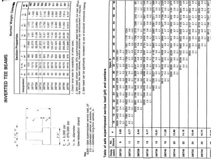
7 PRECAST CONCRETE PLANK FLOOR SYSTEM In order to reduce system weight and floor thickness, precast structural floor planks were considered for two conditions: 1. Double-T Planks 2. Hollowcore Concrete Planks The Prestressed Concrete Institute Manual was used for member sizing. Since planks capable of supporting heavier parking loads are designed for long spans, more analysis and possibly a new layout would be necessary to size members in the parking structure. Loads for the office building redesign include: 100 psf Live Load (open office) 15 psf superimposed Dead Load (MEP, finishes) Controlling D + L service load combination Double-T Planks. Office Building Design Results: (see Appendix C) 8-0 wide by 12 deep Double-T lightweight concrete Planks, untopped, number 48-S, spanning in the north-south 20-0 direction 12 wide by 28 deep precast concrete beam or W24x55 steel girder spanning in the east-west 30-0 direction estimated floor thickness 29.4k-47.4k average bay weight Hollowcore Concrete Planks. Office Building Design Results: 4-0 wide by 8 deep Hollowcore lightweight concrete Planks, number 66-S, spanning in the north-south 20-0 direction 12 wide by 32 deep precast rectangular girder, 12 wide, 28 deep inverted T- beam, or W21x62 steel girder spanning in the east-west 30-0 direction estimated floor thickness 40.3k-69.6k average bay weight Precast concrete planks proved to provide among the narrowest floor section depths and one of the lightest average bays. Since they are prefabricated, initial quality is expected to be superior, quick and easy construction offsets the more expensive initial costs, and, unlike steel systems, a two-hour fire rating is already achieved through the planks. Ample room would be provided for additional engineered systems between girders for both systems. However, since this system is prefabricated, longer lead times would be necessary to procure the necessary planks, and the benefits of thin precast planks are overshadowed by deep precast concrete beams or non-composite steel girders. 7
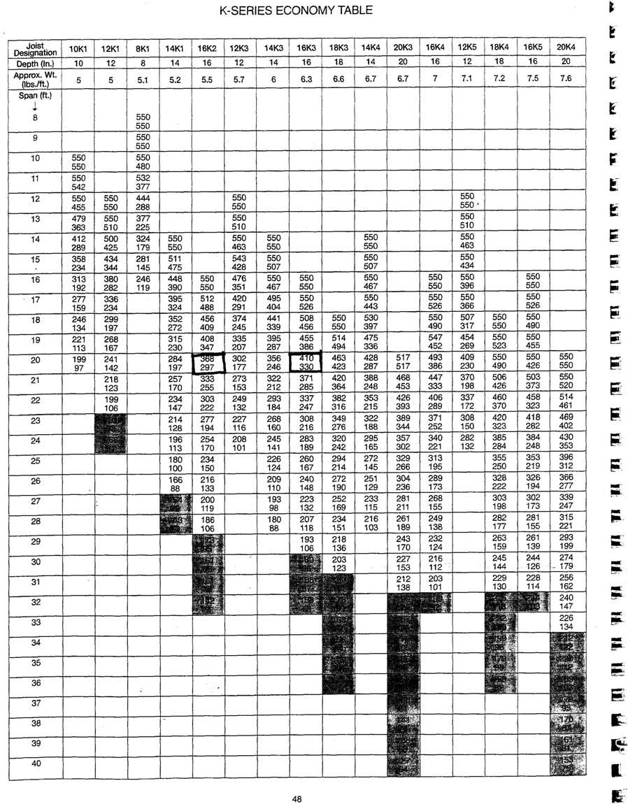
8 STEEL JOIST FRAMING When considering the larger loads in the open office building and parking structure, prefabricated steel joists were analyzed due to their light weight and longer span capabilities. Two conditions were considered: 1. Joists spanning the shorter 20-0 north-south direction, and 2. Joists spanning the longer 30-0 east-west direction. Specification guides provided by the New Columbia Joist Company were used to size the individual joists while hand calculations were used to determine appropriate supporting girder sizes. Loads for the office building redesign include: 100 psf Live Load (open office) 10 psf superimposed Dead Load (MEP, finishes) 60 psf Dead Load from 3 Composite Steel Deck and 3.5 lightweight concrete slab Controlling D + L service load combination Loads for the parking structure redesign include: 250 psf Live Load (fire engine loads) 93 psf Dead Load from 2 deck with additional 4.5 normal weight concrete slab and additional 4 asphalt topping 30 psf snow load Controlling D + L + S service load combination North-South Span. This alteration seeks to minimize joist depth by spanning them in the shorter direction. Office Building Design Results: (see Appendix D) 16K2 Joists spaced 2-0 O.C. W21 Girders 27.5 estimated floor thickness 47.5k average bay weight Parking Structure Design Results: 16K3 Joists spaced 12 O.C. W30 girders 40.5 estimated floor thickness 65.7k average bay weight 8
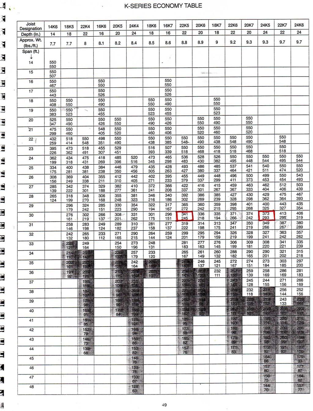
9 East-West Span. This alteration seeks to minimize overall floor thickness through minimizing girder depth by taking advantage of the long-span capabilities of Steel Joists. Office Building Design Results: 22K5 Joists spaced 2-0 O.C. W21 Girders 27.5 estimated floor thickness 46.8k average bay weight Parking Structure Design Results: 24K5 Joists spaced 12 O.C. W24 girders 34.5 estimated floor thickness 65.1k average bay weight The steel joist system provided a very light building weight and surprisingly an equal or slightly smaller floor section thickness than in traditional steel framing, especially under the large parking structure loads. While the joists were closely spaced, open areas in the webs would provide spaces for narrow mechanical ductwork and systems. In addition, open web steel joist construction is much simpler than composite steel beams. However, complicated fireproofing and long procurement times could affect the viability of this solution. 9
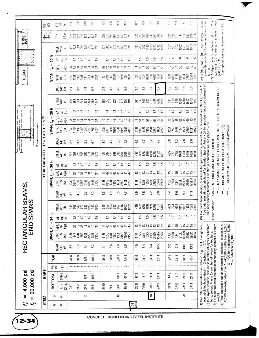
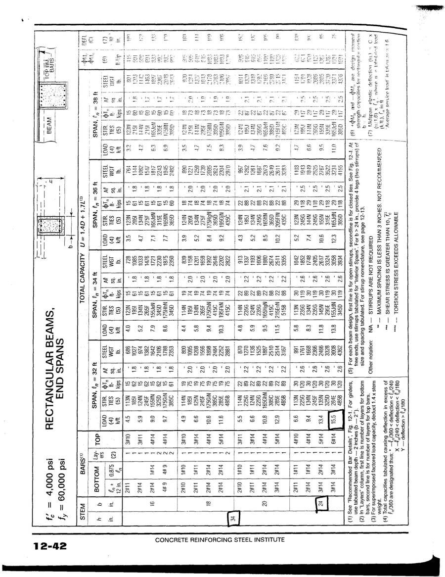
10 ONE WAY CONCRETE SLAB In an effort to reduce overall floor thickness, increase structural rigidity, and improve fire resistance, concrete slabs and beams were considered. Due to the rectangular (20-0 x30-0 ) spans, two-way slabs would not be possible without a significant column redesign. The CRSI was used for this analysis, assuming normal strength concrete and standard concrete forms. Loads for the office building redesign include: 100 psf Live Load (open office) 15 psf superimposed Dead Load (MEP, finishes) Controlling 1.4D + 1.7L load combination Loads for the parking structure redesign include: 250 psf Live Load (fire engine loads) 50 psf Dead Load from 4 asphalt topping (conc. self-weight only for beams) 30 psf snow load Controlling 1.4D + 1.7L + S load combination Office Building Design Results: (see Appendix E) 7 thick concrete slab, spanning in the 20-0 north-south direction, with #6@10 top reinforcement and #6@11 bottom reinforcement 26 deep by 16 wide concrete beams, spanning in the 30-0 east-west direction, poured integrally with the slab, using 3-#10 top reinforcement and 2-#10 bottom reinforcement. 26 estimated floor thickness 72.5k average bay weight Parking Structure Design Results: 10 thick concrete slab, spanning in the 20-0 north-south direction, with #8@12 top reinforcement and #8@13 bottom reinforcement 32 deep by 24 wide concrete beams, spanning in the 30-0 east-west direction, poured integrally with the slab, using 6-#14 top reinforcement and 3-#14 bottom reinforcement. 36 estimated floor thickness 123.0k average bay weight The key benefit to the one-way slab was the reduction in floor thickness. Besides being on average 1.5 narrower than all but one steel floor construction, the lack of joists produces large areas below the slab for additional engineered systems. Unlike steel framing, fireproofing is not a concern with a 7 thick slab; like traditional steel framing, a one-way slab is relatively easy to construct. Since a concrete floor is capable of acting as an effective diaphragm for lateral force resistance, shear walls would be the key lateral structural system, requiring some architectural redesign around the corridor area. 10
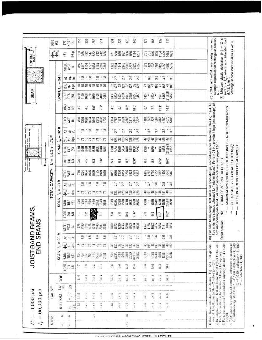
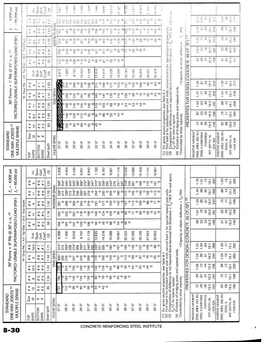
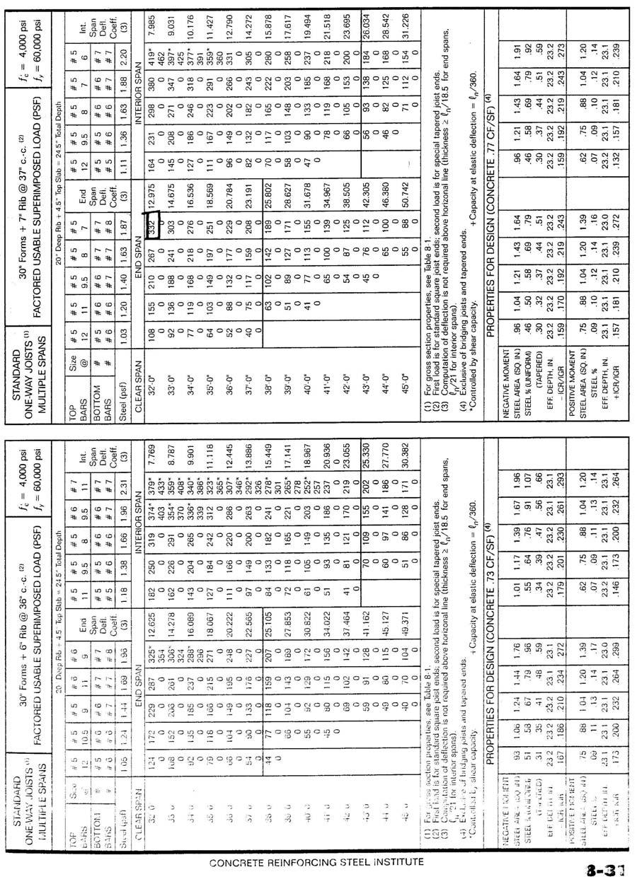
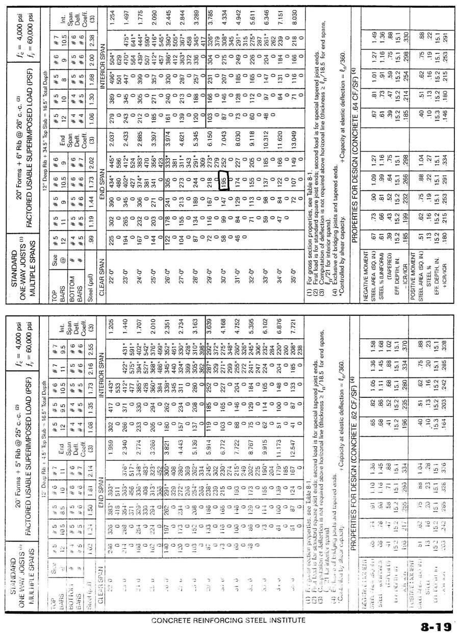
11 PAN JOISTS While using a concrete floor structure, Pan Joists were considered to reduce the overall floor thickness and more efficiently use concrete materials. For this alternative, two conditions were considered: 1. Pan Joists spanning the shorter 20-0 north-south direction, and 2. Pan Joists spanning the longer 30-0 east-west direction. The CRSI was used for this analysis, assuming normal strength concrete and standard concrete forms. Loads for the office building redesign include: 100 psf Live Load (open office) 15 psf superimposed Dead Load (MEP, finishes) Controlling 1.4D + 1.7L load combination Loads for the parking structure redesign include: 250 psf Live Load (fire engine loads) 50 psf Dead Load from 4 asphalt topping 30 psf snow load Controlling 1.4D + 1.7L + S load combination Per the CRSI, self-weight of concrete was only considered for beam sizing. North-South Span. This alteration seeks to mimic most closely the existing system. Office Building Design Results: (see Appendix F) 6 wide, 16 deep ribs spaced 36 O.C., spanning in the 20-0 direction 4.5 thick concrete slab, poured monolithically with the joists, with #4@8 top reinforcement and 1-#5/1-#6 bottom reinforcement 20.5 deep by 24 wide girder, poured monolithically with the joists, spanning in the east-west 30-0 direction estimated floor thickness 80.95k average bay weight Parking Structure Design Results: 7 wide, 20 deep ribs spaced 37 O.C., spanning in the 20-0 direction 4.5 thick concrete slab, poured monolithically with the joists 24.5 deep by 48 wide girder, poured monolithically with the joists, spanning in the east-west 30-0 direction estimated floor thickness 116.0k average bay weight 11
12 East-West Span. In order to reduce the total concrete used, this alteration seeks to minimize the girder size through spanning joists in the longer 30-0 east-west span. Office Building Design Results: 6 wide, 12 deep ribs spaced 26 O.C., spanning in the 30-0 direction 4.5 thick concrete slab, poured monolithically with the joists, with #4@11.5 top reinforcement and 1-#4/1- #5 bottom reinforcement 16.5 deep by 36 wide girder, poured monolithically with the joists, spanning in the north-south 20-0 direction estimated floor thickness 67.0k average bay weight For the east-west span under office loads and north-south span under parking loads, Pan Joists were determined to be a very good possibility for redesign. Besides being the narrowest, with floor section depths 4 and 7 less than composite steel designs in the office and parking structure, respectively, it is also the lightest concrete system. Though a little more complicated for construction than a one-way slab system, standard pan sizes can be reused throughout the building. Unlike the one-way slab system, a thin (4.5 ) slab means that complex fireproofing would have to be addressed or the slab would need to be thicker and heavier; like all other concrete systems, shear walls would be most likely the best lateral force resisting system, which would require a redesign around the central stairwell and corridor area. 12

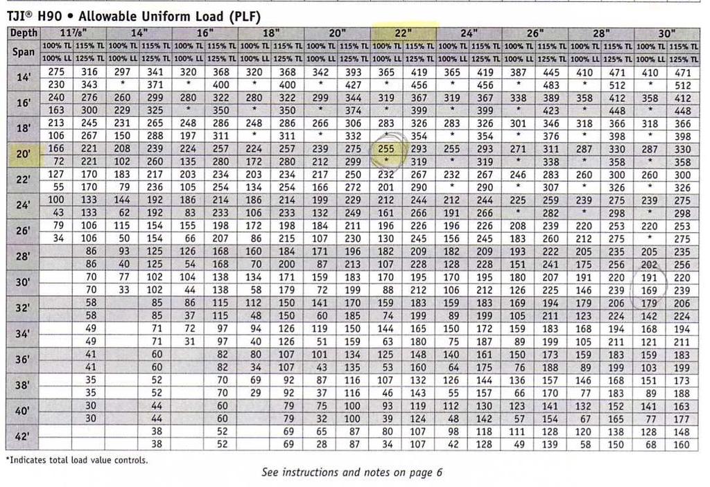
13 MANUFACTURED WOOD FRAMING Though not typical for commercial office buildings, TrusJoist manufactured wood joists and girders were investigated due to their high quality, light weight, and possible benefits. For this alteration, two conditions are considered: 1. Wood Joists spanning the shorter 20-0 north-south direction, and 2. Wood Joists spanning the longer 30-0 east-west direction. For this analysis, specifications provided by TrusJoist literature were used to size joists and girders based on service loads. Loads for the office building redesign include: 100 psf Live Load (open office) 20 psf superimposed Dead Load (MEP, finishes, wood floor panels) Service Loading Per the specifications, self-weight of wood was not considered. North-South Span. This alteration seeks to mimic most closely the existing system and serve as a comparison for steel and concrete pan joists. Office Building Design Results: (see Appendix G) 22 deep by 3.5 wide TJI H90 wood joists spaced 24 O.C., spanning in the 20-0 direction Traditional Plywood flooring 34 deep by 7 Parallam commercial girders spanning in the 30-0 direction 34.5 estimated floor thickness 18.4k average bay weight East-West Span. In order to reduce the total floor thickness via thinner girders, wood joists spanning in the larger 30-0 east-west direction were considered. Office Building Design Results: 30 deep by 3.5 wide TJI H90 wood joists spaced 18 O.C., spanning in the 30-0 direction Traditional Plywood flooring 30 deep by 7 Parallam commercial girders spanning in the 30-0 direction 30.5 estimated floor thickness 17.44k average bay weight Due to the relatively large loading and flexibility of wood members, wood joist framing was not considered for the parking garage. 13
14 Though unconventional for suburban office buildings, wood framing could be a viable alternative for the office structure, and could serve as a distinct architectural addition to its interior appearance. Especially with wood joists spanning in the larger east-west direction, the floor depth is only 4 greater than a non-composite steel system, and the average bay weight is about 60% less. Due to the nature of its unconventional construction, issues of floor flexibility and vibration isolation, fire resistance in combustible members, and overall performance characteristics would need to be analyzed, and, like the concrete structures, shear walls, perhaps using another material, would need to be designed around the central stairwell/corridor area as the lateral force resisting system. 14
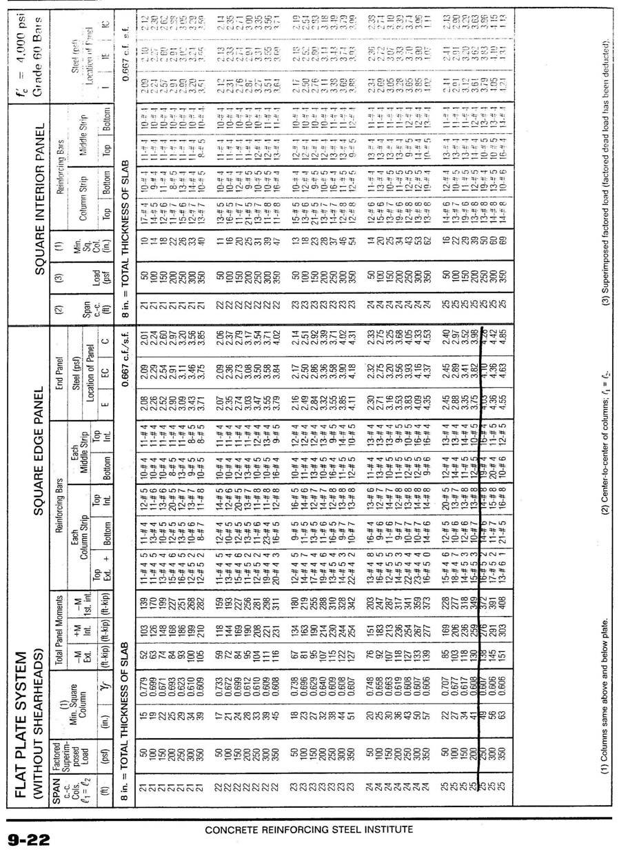
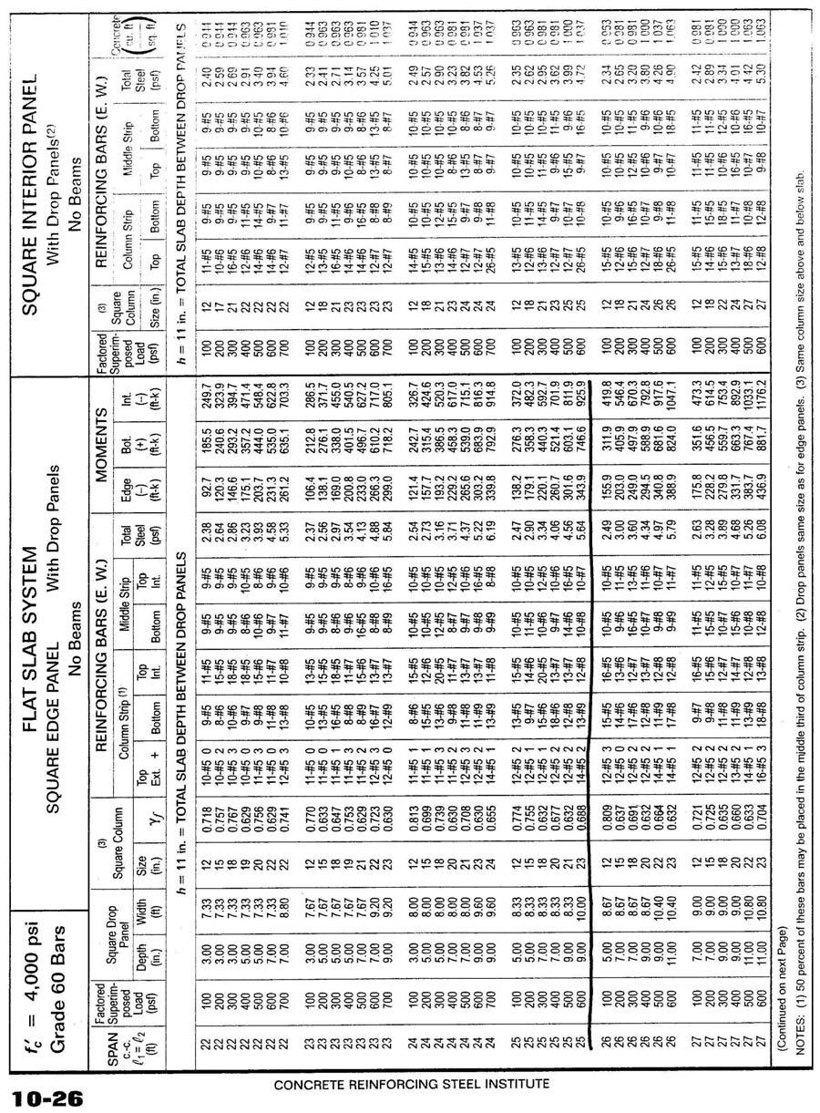
15 TWO WAY SLAB Two-way slabs can have smaller floor section depths and simpler construction. Since a two-way slab is impractical with rectangular bays, this redesign would only be possible if the 165 x 75 building footprint were arranged into bays ranging from 20 x 25 to 25 x 25. (see Appendix H) Loads for the office building redesign include: 100 psf Live Load (open office) 15 psf superimposed Dead Load (MEP, finishes) Controlling 1.4D + 1.7L load combination Loads for the parking structure redesign include: 250 psf Live Load (fire engine loads) 50 psf Dead Load from 4 asphalt topping (conc. self-weight only for beams) 30 psf Snow Load Controlling 1.4D + 1.7L + S load combination With Drop Panels. A potential design using this system included: 9 flat slab with 7 deep, 9-0 square drop panels for the office building, 11 flat slab with 9 deep, 9-0 square drop panels for the parking structure. Flat Slab. A potential design using this system included: 8 flat slab throughout office building. This system would work most effectively with bay sizes approaching 20-0 square. Since the building features an open floor plan, with only corridors, bathrooms and stairwells explicitly laid out in the building center, it would be easier to design the building for three 25-0 wide north-south bays and two 20-0 and five 25-0 wide eastwest bays. As the bays would approach a 20-0 square spacing, a two-way slab would become more practical. 15
16 CONCLUSIONS A cursory analysis of varying structural systems designed to resist gravity loads for both a four story office building and its supporting parking garage showed that: When beams are spanned in the longer East-West direction, deflection tends to control over flexural capacity, producing much larger beams. However, girder size is significantly reduced. Concrete systems are significantly heavier than all other systems. Though soil bearing capacities aren t a major factor in this particular building design, larger building weights would cause larger footings and foundation elements. Composite Steel systems are the lightest and provide ample room in the floor section for additional engineered systems. However, these systems are slightly more complicated to construct than non-composite systems, and moment frames become necessary for lateral force resistance. Non-Composite Steel systems are simpler to construct than composite systems, though large floor section depths are necessary. Prefabricated Concrete Plank systems are most easy to install and maintain high quality and can provide significantly lighter average bays and relatively thinner floor section depths. Precast Planks resting on non-composite steel beams is the most viable system. Steel Joists provide ample room for additional engineered systems and actually feature floor section depths similar to traditional steel framing systems. Easy installation would be offset by long procurement times, while complicated fireproofing would need to be addressed. One-Way Concrete slabs, though heavy, provide a sturdy floor diaphragm to resist lateral forces when in combination with shear walls, and provide spaces for additional engineered systems. Pan Joists are the most viable concrete alternative with very small section depths and relatively light weight. Joists every 20 or 30 however may inhibit additional engineered system placement. TrusJoist manufactured Wood Joists and Parallam beams provide a superlightweight structure which has only a slightly larger depth than non-composite steel systems. However, further research is necessary into performance characteristics of wood structures before it is applied to an office building. See the following comparison table for a summary. 16
17 STRUCTURAL FLOOR SYSTEM COMPARISON TABLE Floor System Composite Steel, N/S Span Composite Steel, E/W Span Non-Composite Steel, Given Layout Non-Composite Steel, Narrower N/S Span Non-Composite Steel E/W Span Prefabricated Concrete Double-T Plank Prefabricated Concrete Hollowcore Plank Depth (in) 27.5 (O) 34.5 (P) 20.5 (O) 31.5 (P) 30.5 (O) 40.5 (P) 30.5 (O) 40.5 (P) 27.5 (O) 37.5 (P) (O) (O) Bay Wt. (kips) 46.0 (O) 63.2 (P) 46.3 (O) 63.7 (P) 48.2 (O) 64.7 (P) 48.5 (O) 65.2 (P) 49.1 (O) 66.3 (P) (O) (O) Pros Cons Further Analysis? Lightweight Additional N/A Fast Construction Fireproofing required Narrow Floor Moment Frame Section Depth most possible lateral Lightweight Fast Construction Narrow Floor Section Depth Lightweight Traditional Construction Lightweight Traditional Construction Lightweight Traditional Construction Reduced Floor Section Depth Good Fire Rating High Initial Quality from prefabrication Easy, Fast Construction Good Fire Rating High Initial Quality from prefabrication Easy Construction system Additional Fireproofing required Moment Frame most possible lateral system Additional Fireproofing required Moment Frame most possible lateral system Large Floor Section Depth Additional Fireproofing required Moment Frame most possible lateral system Large Floor Section Depth Multiple Joists inhibit MEP system placement Additional Fireproofing required Moment Frame most possible lateral system Enlarged beams for deflection due to long 30-0 span Can have larger floor section depths Long Procurement needed for planks Can have larger floor section depths Long Procurement needed for planks Yes No No Yes Yes Yes 17
18 STRUCTURAL FLOOR SYSTEM COMPARISON TABLE, CONTINUED Floor System Depth (in) Bay Wt. (kips) Pros Cons Further Analysis? Steel Joists, N/S Span Steel Joists, E/W Span One-Way Concrete Slab Concrete Pan Joists, N/S Span Concrete Pan Joists, E/W Span Wood Framing, N/S Span 27.5 (O) 40.5 (P) 27.5 (O) 34.5 (P) 26.0 (O) 36.0 (P) 20.5 (O) 24.5 (P) 47.5 (O) 65.6 (P) 46.8 (O) 65.1 (P) 72.5 (O) (P) 81.0 (O) (P) Lightweight Fast Construction Open Web Joists provide spaces for MEP placement Lightweight Fast Construction Open Web Joists provide spaces for MEP placement Easy, Simple Construction Narrow Floor provides space for MEP systems Good Fire Rating Floor Diaphragm capable of resisting lateral forces Very narrow floor section depth Lightest Concrete Construction Standard Pan Sizes Easy Construction 16.5 (O) 67.0 (O) Very narrow floor section depth Lightest Concrete Construction Standard Pan Sizes Easy Construction 34.5 (O) 18.4 (O) Most Lightweight Easy Joist/Hanger Construction Generates Visual Interest Average Floor Depth High quality prefabrication w Complicated Fireproofing required Moment Frame most possible lateral system Very Large Floor Section Depth Complicated Fireproofing required Moment Frame lateral system Very Large Floor Section Depth Very Heavy Weight Shear Walls most likely needed for lateral system Possible foundation redesign for weight Complicated Fireproofing required Shear Walls most likely needed for lateral system Possible foundation redesign for weight Complicated Fireproofing required Shear Walls most likely needed for lateral system Possible foundation redesign for weight Complicated Fireproofing required Shear Walls most likely needed for lateral system Flexible Floor Diaphragm subject to vibrations and creaking Close Joists inhibit MEP placement No No Yes Yes No Yes 18
19 STRUCTURAL FLOOR SYSTEM COMPARISON TABLE, CONTINUED Floor System Wood Framing, E/W Span Two-Way Concrete Slab with Drop Panels Two-Way Flat Slab Depth (in) Bay Wt. (kips) Pros Cons Further Analysis? 30.5 (O) 17.5 (O) Most Lightweight Complicated Yes Easy Fireproofing required Joist/Hanger Shear Walls most Construction likely needed for Generates Visual lateral system Interest Flexible Floor Average Floor Diaphragm subject to Depth vibrations and High quality, creaking prefabricated Close Joists inhibit MEP placement 15.0 (O) 83.8 (O) No 20.0 (P) (P) 8.0 (O) 69.0 (O) Good Fire Rating Small Floor Section Depth Good Fire Rating Very Narrow Floor Section Depth Lighter than One- Way Slab Very Easy to Construct Complicated Construction around Drop Panels Requires New Layout Very Heavy possible foundation redesign required Requires New Layout Very Heavy possible foundation redesign required Yes 19
20 APPENDIX A: COMPOSITE STEEL DESIGN CALCULATIONS/REFERENCES 20
21 21
22 APPENDIX B: NON-COMPOSITE STEEL DESIGN CALCULATIONS/REFERENCES 22
23 23

24 APPENDIX C: PCI PRECAST CONCRETE PLANK DESIGN CALCULATIONS/REFERENCES 24
25 25

26 26
27 APPENDIX D: STEEL JOIST FRAMING DESIGN 27
28 28
29 29
30 30
31 APPENDIX E: ONE-WAY SLAB DESIGN CALCULATIONS/REFERENCES 31
32 32
33 33
34 34
35 APPENDIX F: PAN-JOIST DESIGN CALCULATIONS/REFERENCES 35
36 36
37 37
38 38
39 39
40 40
41 41
42 APPENDIX G: TRUSJOIST MANUFACTURED WOOD PRODUCTS DESIGN CALCULATIONS/REFERENCES 42

43 43
44 APPENDIX H: TWO-WAY SLAB DESIGN CALCULATIONS/REFERENCES 44
45 45
46 46
47 47