otection Rockfall Pr
|
|
|
- Theodore Hall
- 5 years ago
- Views:
Transcription

1 Rockfall Protection

2

3 Rockfall Protection Problems and Solutions General issues Specific problems System solutions Specific solutions

4 04 Risk analysis Roads, railways and urban areas are frequently subjected to instability of rock slopes. Such instabilities can affect the superficial portion of the slope or involve its entire global stability. Rockfall systems can be designed to act on the surficial layer of the slope only or they can act deeply within the rock mass to consolidate large blocks or stabilize the whole slope. A clear distinction must be made at the outset between surficial protection, applied using a combination of steel meshes, steel cables, cable panels and anchors (presented in this brochure), and the works aimed stabilizing the rock slope against global instability problems (not part of this brochure). For the latter, the same superficial protections are normally applied, together with solutions specifically designed for the global slope stability. It is incorrect to assume that the same intervention techniques dedicated to superficial portion of the slopes can be applied, without other works, for deep seated instabilities. Surficial instabilities are related to alterations and deterioration of the rocks due to plant root action, thermal expansion, wind and salt erosion, slope excavation methods, freeze and thaw processes, progressive weathering of joints within rocks, hydrostatic pressures, seismic action and so on. Only in limited cases can these problems be reduced to a simple solution. Rather, quantitative risk assessment should be undertaken to adequately and efficiently quantify the risks associated with possible landslides for a particular slope or set of slopes. The risk assessment should weigh up the probability, magnitude and distribution of occurrences and, on the other hand, take into account the unforseen and undesirable consequences of casualties, property damage and loss of service. Risk management should focus on the identification of potential key risk factors which are then logically evaluated in terms of probability, costs and other benefits, so as to manage the risk in an optimal way. SURFACE SLOPE INSTABILITY PROTECTION STRATEGY PASSIVE PROTECTION SYSTEM Control of instability effects TRENCHES, ROCK FENCES AND ROCKFALL PROTECTION EMBANKMENTS DRAPERY SYSTEMS SURFICIAL REVETMENTS SOIL NAILING TIE BACK ANCHORS ACTIVE PROTECTION SYSTEM Instability prevention


5 05 Rockfall protection Rockfall protection systems are a key element in the design and maintenance of road and railway infrastructure networks and have a direct impact on safety. For this reason, a new approach that encompasses the overall analysis of the rockfall structural system, and not just the individual components, is necessary. The word system is the best description, as it embraces the different structural components that interact with one another. A key distinction must be made between active and passive protection systems. Passive systems are those which do not affect the process of the rock detachment, but rather focus on containing and intercepting falling and sliding debris, thereby averting danger to infrastructure and its users. Passive systems include: - Simple drapery systems - Rockfall protection barriers - Rockfall protection embankments Active systems are those that act to prevent and control in a significant way rock detachments: - Surficial reinforcing systems, where different kinds of steel wire and steel cables form an armoured mesh which is then fixed to the rock slope through anchor bars. - Pre-stressed and tie back anchors. The planning, construction and maintenance of these structures must take into account the durability. In accordance with these concepts, Maccaferri s long-earned experience in this field, coupled with its corporate orientation towards research and innovation, has yielded the development of the MAC.RO. System (MACcaferri ROckfall protection systems). MAC.RO. provides flexible solutions tuned to different problems and combines industrial innovation and advanced research with project design. Simple drapery system Rockfall barriers Scascoli (BO) - Italy Belluno - Italy Rockfall protection embankments Surficial reinforcing systems Cogne (AO) - Italy Madeira - Spain


6 The MAC.RO. System The concept behind a rockfall protection system is a combination of good planning with the right choice of system components and materials. The choice has to be based on the actual forces the system will have to withstand, compared to the strength limits of the different elements of the system. As it has always been with all soil stabilization works, the basic concept Maccaferri comply with is the minimum energy level, i.e. an intervention carefully tuned to the problem, thereby avoiding over-design and unnecessary costs. Durability aspects of rockfall systems are regulated by the Durability and Construction Products Directive 89/106/EEC guideline. The period of time during which the system performs as expected is directly connected to the durability of the system components and the level of maintenance; a concept known as working design life. Rockfall protection barriers and surficial systems are non-easily replaceable systems, and therefore they must have a 25 year working life; on the other hand, reinforced earth embankments for rockfall protection must be designed for a minimum 50 year working life. Double knot to fix the overlapping rope in the HEA cable panel Action Aim Typical applications Trenches and walls at the foot of a slope Intercepting and stopping falling rocks and boulders Protection of roads running at the bottom of man-made cuttings Durability of facings and systems Very aggressive environment (industrial, road and marine) Rockfall protection - required life-span Reinforced rockfall protection embankments - required life-span Class A EN Passive Rock fences with high energy dissipation capacity Rockfall protection barriers, made on-site Intercepting and stopping falling rocks and boulders Intercepting and stopping falling rocks and boulders Protection of roads and buildings at the foot of natural cliffs Interception of falling rock paths in rocky slopes Loss of Coating (gr/m 2 ) Zn Zn-Al (5%) MM Zn-Al (5%) MM polymersheathed Time (years) Active Simple drapery system Surficial strengthening Soil nailing Deep consolidation, with nails and ties Controlling rockfall, guiding falling debris to collect/ accumulation at the foot of the slope Consolidating the slope s surface and preventing possible rock detachment Global stabilisation of the slope Stabilisation of huge rocks, individual or in groups, which are prone to seismic shifting Protection of road cliffs and buildings, also in combination with trenches and/or walls Protection of road cuts and buildings Management of slope cuts Natural cliffs, slope cuts Steel Galfan Zn-Al 5%-MM Alloy Steel Galfan Zn-Al 5% -MM Alloy Polymer sheathing 06


7 07 MAC.RO. System The solutions provided by the MAC.RO. system have been developed in collaboration with noted research centres. In this way Maccaferri not only provides products, but also the fundamental technical assessments needed in order to achieve the optimum action planning. SIMPLE DRAPERY SYSTEM SOIL NAILING Steelgrid MO Accessories Macmat R Steelgrid BO Accessories CNR/ITC Milan - Italy SURFICIAL STRENGTHENING Steelgrid BO HEA panel Accessories CTR 05/07/B CTR10/04/B LA.T.I.F. Trento - Italy ROCK FENCES CTR 20/04/B CTR 20/04/A OM CTR 30/04/A OM CTR 50/07/A ROCKFALL PROTECTION EMBANKMENTS Terramesh doubleface Pont Boset (AO) - Italy Università di Milan Italy CETE - Lyon - France


8 11 08 Rockfall embankments Simple drapery systems Surficial reinforcing systems Surficial reinforcing revetments Rockfall catch fences Soil nailing
 and not larger than 0.5 metres in diameter.")


9 09 Simple drapery system Simple mesh draperies are usually installed along rock slopes whose surface can break down into fragments not smaller than the opening of the double twisted mesh (60mm to 80mm) and not larger than 0.5 metres in diameter. On moderately steep slopes, or slopes where some vegetation may grow, the mesh should be kept as close as possible to the slope. On very steep or nearly vertical slopes, the mesh net must be anchored at the top and bottom of the cliff and left unanchored along the slope. This allows small rocks and debris to fall safely to the foot of the cliff, whilst remaining contained between the rock face and the mesh. To limit the containment area between the mesh and rock face some nailing or pegging of the mesh at intervals between the top and bottom anchorage may be necessary. The most important aspect here is to have a safe and continuous anchorage at the top and provide sufficient space to allow rocks and debris to move downwards. Our doubletwist wire mesh is the ideal solution due to its isotropic flexibility and the fact that it will not unravel even in the event of some wires accidentally breaking. Single twist mesh cannot provide the same level of safety in the event of wire breakage, irrespective of the strength and type of wire used. Guiding loose debris to fall safely behind the mesh collecting material at the foot of the slope. Protection of infrastructure and buildings placed directly at the foot of man-made cuts or natural cliffs. Containment of small falling rocks from rock slopes prone to deterioration as a result of root action, thermal expansion, winds, freeze thaw cycles, and hydrostatic pressures. Ancona - Italy Cork - Ireland Madeira - Spain

, with a suggested safety factor of 3.")

10 10 Fixed drapery systems The design of a drapery system as a whole should be undertaken only after a realistic assessment of the site conditions have been established, and in accordance with the general planning guidelines laid out in the Eurocode design standards. The main contributing factors that should be stressed and considered are: - The permanent loads: weight of the whole netting, with a recommended partial safety factor of The variable loads: weight of debris piled up at the foot and/or weight of snow (for slopes less than 60 ), with a suggested safety factor of 3. In general, the dynamic actions produced by a rock sliding between the drapery and rock face can be disregarded except in specific situations in which the rockfall system has not been designed or installed in the correct way. Other than that, the main stresses are due to the accumulation of debris at the foot of the slope. Maccaferri has developed Steelgrid, a new double twisted wire mesh with high tensile steel cables woven within the double mesh during the production stage. The resulting product is midway between a cable reinforced mesh and a steel cable panel, ideal as a surface revetment. However, the great economic benefit of Steelgrid is achieved from the fact that two different products can be installed simultaneously (mesh and steel cables), reducing overall project costs and saving installation time. STEELGRID MO (Mono Oriented) consists of double twisted wire mesh where the usual selvedge wires are replaced by 8 mm diameter high tensile steel ropes. An additional 8 mm diameter steel rope may be inserted longitudinally midway between the selvedges in the woven mesh. This system is the natural evolution of the typical simple drapery system. Steelgrid MO Mono Oriented Anchor at the base of the slope Bologna - Italy


11 Volume of debris at the foot of the slope The volume of debris is evaluated not only in order to design the drapery system, but also to determine the extent and type of the most suitable rockfall system to be installed. It is important to assess what the likely amount of accumulated debris will be at the foot, since this will have an impact on the admissible distance between the foot of the slope and the road surface. In other words, the designer should have a reasonable idea of the acceptable quantity of debris, and refrain from drawing catastrophic scenarios to justify the assumed requirement of a higher resistance system. The figures here show the volume of debris corresponding to a base width of 1.00 metre in relation to a accumulated height up to 3.00 metres. Volume at the foot (m 3 /m) V d 1,8 1,6 1,4 1,2 1,0 0,8 0,6 0,4 0,2 0 V d 1,00 0 1,00 2,00 3,00 H d (m) H d Evaluation of the suitability of the net in simple drapery systems, using the MACRO2. software Bergamo - Italy Forces on the Drapery The force bearing upon the drapery is a function of the slope angle and must be evaluated using ultimate limit state conditions, taking into account the friction between the debris and the slope and the previously mentioned safety factors. S wm Shear Force on facing (kn/m) β = 80 β = 70 β = 60 Strain on facing S wm 1,00 β H d 0 1,00 2,00 3,00 H d (m) Torino - Italy 11


12 12 Rock Slope Surficial Reinforcing Systems A surficial reinforcing system is aimed at the stabilization of the rock mass surface layer containing potentially unstable rocks of a size typically m 3. This type of work can be classified under the active systems rather than the passive, although it could be argued as a combination of both. It should be highlighted that a "surface revetment installation is different from the global stability of the rock surface. The latter, if the problem exists, must be addressed with deep penetrating measures (e.g. soil nailing, deep anchors), which may then be coupled with a facing system/drapery (made with a series of anchors, mesh and cables) to achieve surface stability. The complete system consisting of anchors, steel cable panels, steel cables and mesh netting, as detailed below, is a basic unit or cell enclosed between 4 anchor points. To determine the most suitable system, the following information must be assessed: - the stiffness or rigidity of the facing (drapery) - the forces transmitted to the anchors. In these kinds of problems, it is crucial that the drapery provides a high resistance with minimal deflection in order to limit the displacement of the rock mass. The stiffness of a drapery system can be defined as the resistance to the displacement when the facing, anchored in the standard manner, is subjected to movement perpendicular to the plane of the system. Prevent the possibility of rocks detaching and improve the slope surface stability. Consolidation of the shallow surface layer of the slope. Protection of infrastructure and buildings placed directly at the foot of man-made cuttings or natural cliffs. Containment of large unstable rocks in slopes prone to weathering caused by root plant action, thermal expansion, winds, freeze and thaw cycles, and hydrostatic pressures. metal cables and double-twist mesh panels anchorage metal cables

 combining benefits of both.")


13 Types of facing A steel cable or steel cable panel such as the HEA panels developed by Maccaferri, is more effective than woven wire meshes on their own for slope consolidation applications, and this is unrelated to the mechanical properties of wire. In addition, double-twist wire mesh is also more effective than single twisted mesh, due to its higher stiffness. With this in mind, Maccaferri has developed Steelgrid BO (Bi Oriented) combining benefits of both. This geocomposite is particularly suitable in rockfall protection as a surficial reinforcing system for slope consolidation applications. Its great advantage lies in the ability to connect the integral longitudinal ropes to the top anchor cable, and the horizontal ropes to the anchorage pattern along the slope. Furthermore, the woven steel ropes inside the wire mesh increase the drapery stiffness, resulting in improved safety and more effective facing. Steelgrid BO (Bi Oriented) consists of 8 mm diameter high tensile steel ropes, in place of the conventional selvedge wire, with a further 8 mm diameter steel rope inserted longitudinally midway between the selvedges. During the production stage, steel ropes are also inserted transversely in the cross direction through the mesh twist and secured to the edge ropes with ferruled loops. HEA Panel Steelgrid BO Bi Oriented Bologna - Italy Anchor and Steelgrid panels' junction 13 Evaluation of the facing behaviour in surficial revetments, using the MAC.RO. 1 software
 are fixed with high-resistance 3 mm wire knots.")


14 14 HEA steel cable panels HEA panels are manufactured from a single high tensile steel rope, woven to form a panel diamond shaped mesh. The meshes (where the cables overlap) are fixed with high-resistance 3 mm wire knots. HEA panels have been tested for the following features: - resistance of the knot to tear and pull apart - resistance of the knot against the opening of one single mesh in static conditions - deformation of the HEA panel under static load - load transmitted to the anchors Comparative tests carried out on traditional cable panels, where the meshes are fixed with clips, demonstrated that Maccaferri s HEA panels perform better and are of better quality. In the case of the knot connection, after the limit resistance is reached, the knot progressively unties itself until the breaking point of one of the wires is reached. With traditional clip connection systems, the connection suddenly fails when the limiting resistance is exceeded producing immediate unravelling of the panel. When high strength is required (> 192 kn) When a facing with high stiffness is required Junction resistance Type of junction HEA Panel Resistance to tear kn 24,4 Resistance to pull apart kn 11,9 High resistance clips 13,5 8,0 Low resistance clips 4,6 1,3 CERMET Bologna - Italy Resistance to mesh opening Force (kn) clips HEA knot Displacement (cm) CNR - ITC Milan - Italy Ancona - Italy PONT BOSET - Aosta Italy

 40 30 20 10 Anchorage 1 Anchorage 2 Anchorage 3 Anchorage 4")


 40 30 20 10 0 0 10 20 30 40 50 60 70")
15 15 Force developed at the anchors Tests to determine the force distribution within an HEA panel clearly show that higher loads were recorded at the panel s corners. On the jobsite, this usually reflects the anchor positions Force (kn) Anchorage 1 Anchorage 2 Anchorage 3 Anchorage Force developed at anchorages CNR - ITC Milan - Italy Punch test resistance Load-displacement curves from lab tests evaluate the stiffness of the surficial reinforcing system, enabling selection of the most suitable facing product in relation to evaluated loads and maximum admissable displacement. 60 CNR - ITC Milan - Italy 50 Force (kn) Displacement (cm) HEA Panel Steelgrid Single-twist mesh, with high-resistance wire


16 16 Catch fences Rockfall barriers of variable geometry are made of a complex system of steel cable panels or ring net panels, a double-twist wire mesh layer for the containment of small rock fragments, steel cables connected to structural elements, posts, energy dissipator devices and anchors. Rockfall barriers dissipate energy with system deformation, thus enabling the system to withstand energies typically in the range of kj. Intercept and stop falling rocks and boulders. Protection of infrastructure and buildings placed directly at the foot of man-made cuttings or natural cliffs. Protection of the slope in the case of very wide cliffs. Maccaferri supplies a system of barriers to cover the full range of energy: from 500kJ up to 5000kJ. These systems were developed through the combination of design and field tests, as required by the official standards (ETAG Guideline for European Technical Approval of Falling Rock Protection Kits ). Rockfall simulation with rockfall interception structure Latina - Italy Rockfall simulation Brescia - Italy
 or interception of falling rocks is not possible due to the whole slope being inaccessible.")


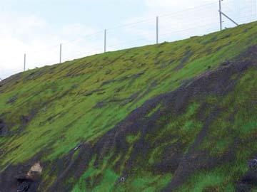
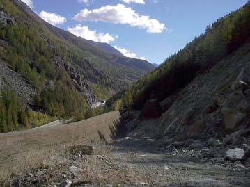
17 17 Rockfall protection embankments These passive systems are an ideal solution when superficial reinforcing system cannot be installed (e.g. for very wide slopes) or interception of falling rocks is not possible due to the whole slope being inaccessible. Nowadays, embankments are increasingly built using reinforced soil, enabling contractors to use locally available materials site won and creating a vegetated embankment facing, which reduces the environmental impact of the system. Intercept and stop falling rocks and boulders. Reduce the environmental impact with re-vegetating solutions. Protection of infrastructure and buildings placed directly at the foot of man-made cuttings or natural cliffs. Divert potential debris flows Maccaferri s Terramesh has been widely used for such works where system effectiveness goes hand-in-hand with rapid building time. The double twist wire mesh units and integral soil reinforcement structural element, are pre-assembled during the manufacturing process, dramatically reducing the number of operations to be performed on site, reducing installation costs when compared to wrap around or separate component systems. Belluno - Italy Aosta - Italy Torino - Italy


18 18 Aosta - Italy Sassari - Italy Aosta - Italy
 or soft (Macmat R) facing is used at the surface of the slope.")


 and at the serviceability limit state (related to the deformation of the product when loaded).")
19 Soil nailing Soil Nailing is a technique that can be used either on natural or excavated slopes. In soil nailing, the soil is reinforced by the insertion of tendons. A hard, flexible (double twisted wire mesh, HEA panels, SteelGrid or Macmat R) or soft (Macmat R) facing is used at the surface of the slope. The facing covers the exposed face of the reinforced soil and may provide a stabilising function to retain the ground between the soil nails, provide erosion protection and have an aesthetic function. Usually the system provides stability while vegetation becomes established: in such way the system improves the soil shear strength, meanwhile providing surface erosion protection. Good practice is to vegetate the face with grass and/or shrubs, and seeding can be carried out by means of a seeded geotextile or hydroseeding. Improve the geo-mechanical characteristics of the soil Connect the unstable surficial layers with the stable deep slope Maccaferri has developed new software to assist in the selection of the product used for flexible and soft facings. Using load-displacement curves obtained by full scale tests on the products, the facing design can be achieved following Eurocode directives. The facing product is checked both at the ultimate limit state (related to the failure of the system) and at the serviceability limit state (related to the deformation of the product when loaded). Maccaferri has also developed a range of products (bolts, facing accessories) to fulfil the specific requirements of flexible structural facing (mesh + deep nails) and soft facing (mesh + short nails). Macerata - Italy AREA 2 Rio de Janeiro - Brasile AREA 1 AREA 3 Anchor bars 19


20 Officine Maccaferri Group Profile Founded in 1879, Officine Maccaferri was soon to become a reference worldwide in the design and development of advanced solutions for erosion control and reinforcement structures. Over time, however, the company has innovated and evolved so that today it is also a reliable partner for complex civil and environmental engineering applications. This aptitude for technological innovation is the result of continuous dedication, which, alongside experience and technical knowhow, has enabled the Maccaferri Group to leverage high levels of efficiency. Concepts transformed into versatile solutions meet our customers specific requirements, whilst maintaining a sustainable environmental balance. Consultancy and partnership Maccaferri does not just offer its customers simple collaboration but a real partnership which goes beyond merely supplying products. Maccaferri is a partner that works alongside its customers from the very start. It is a reliable partner thanks to its extensive portfolio of top quality products. As well as versatile solutions that can be adapted to local situations, it makes its technical know-how available to create a virtual circle in which each factor (products, experience and innovative practice) is improved by each activity. Maccaferri tackles every project with the aim of identifying, dealing with and resolving each customer s actual needs, and the results of this attitude produce benefits which can be appreciated over time. Organizational Structure Maccaferri researches, designs and develops solutions for the construction, erosion protection and soil stabilisation sectors in over 100 countries across the world.the organizational structure has been designed to be global and local at the same time. It is made up of subsidiary companies which make Maccaferri s products and design and offer the company s solutions throughout the world. This ensures greater flexibility, a widespread presence and a better awareness of continued market development. Maccaferri s presence throughout the world allows the company to deal with problems which results in new know-how that, in turn, feeds into further innovation for other solutions offered on the market. As well as the parent company in Italy and subsidiaries in France, Britain, Russia, Spain, the company is also active in all five continents, with more than 60 operating companies. Where there is no internal sales force, there are distributors in all the continents so that all markets are monitored indirectly. ANY REPRODUCTION, INCLUDING PHOTOCOPY, FILM AND MICROFILM, IS FORBIDDEN. ALL RIGHTS RESERVED WORLDWIDE. Bureau Veritas Certified Quality System Company with SINCERT's and UKAS's accreditation Officine Maccaferri S.p.A. Via J.F. Kennedy, Zola Predosa (Bologna) - Italia Tel Fax comes@maccaferri.com Officine Maccaferri S.p.A. - Bologna - Italia - Print: Litografia Zucchini - Project: graficamonti.com - Photo: Archivio Officine Maccaferri