U.S. EDITION RESIDENTIAL CONSTRUCTION DETAILS SAMPLE. A visual guide to construction detailing. Emma Walshaw
|
|
|
- Lesley Barrett
- 5 years ago
- Views:
Transcription

1 RESIDENTIAL CONSTRUCTION DETAILS U.S. EDITION A visual guide to construction detailing Emma Walshaw
2 Contents INTRODUCTION 4 PRINCIPLES OF CONSTRUCTION DETAILING 6 FOUNDATIONS 9 PRINCIPLES OF FOUNDATION DESIGN 10 FOUNDATION DETAILS 18 BASEMENTS 69 PRINCIPLES OF BASEMENT DESIGN 70 BASEMENT DETAILS 74 FLOORS 89 PRINCIPLES OF FLOOR DESIGN 90 FLOOR DETAILS 92 WALLS 111 INTRODUCTION TO WALL DESIGN 112 WALL DETAILS 122 ROOFS 241 INTRODUCTION TO ROOF DESIGN 242 ROOF DETAILS 250 BIBLIOGRAPHY / FURTHER READING 295 INDEX 297 A SPECIAL THANK YOU TO ADAM TOMASZCZYK & JOHNATHON CLOUS FOR THEIR CONTRIBUTIONS TO THE BOOK The information contained in this ebook is for educational purposes only. All rights reserved. No part of this publication may be reproduced, distributed, or transmitted in any form or by any means, including photocopying, recording, or other electronic or mechanical methods, without the prior written permission from the author. Users of this guide are advised to use their own due diligence when it comes to working up construction details. Under no circumstances should any of the contents of this book be used as construction drawings. Drawings must always be checked and verified by a fully qualified architect or associated professional. The entire contents of this book and associated digital files are for educational purposes only. To read the full terms of use follow this link: Copyright 2016 by Emma Walshaw First In Architecture
3 FOUNDATIONS SECTION 1
4 PRINCIPLES OF FOUNDATION DESIGN The main role of foundations is to structurally support the building by transferring the loads of the building through the walls into the surrounding soil. In terms of a stick frame structure, the foundations must also protect the timber from moisture ingress by lifting the members above the ground. The type of soil on the site will have a strong implication to the foundation design. Different regions will have different soil types, the table (Figure 1.1) briefly demonstrates the types of soil and its suitability as a foundation material. From the table you can see how important it is to establish the soil information on the proposed site. This often means a soil study or report is carried out. The second important site factor to consider when designing foundations is cold and permafrost climates. These climates see a level of ground permanently frozen, and the concern is that the soil under the foundation could thaw and lose strength. Specialists should be consulted if designing foundations in an area of cold or permafrost climate (generally the far north - Canada, Alaska and so on). The remaining northern half of the United States and mountainous regions are considered a cold or under heated climate where the frost depth is generally 12in. or greater. The design for this type of climate is a little more straightforward with the following measures taken: Providing foundations below the frost depth Providing a basement Insulating the exterior to reduce the chance of cold ground temperature reaching the structure. TYPES OF FOUNDATION There are four common foundation types in residential construction that all work in quite different ways but each requires a support around the outside edge of the building. The four types are: Slab on grade Pier and grade beam Crawl space Basement For the design of foundations, building codes should be consulted along with local codes to determine appropriate frost depths and design requirements. Foundation choice is dependent on many factors, such as soil type, site, climate and the process of choosing your foundation system goes beyond the scope of this book. FOOTINGS Footings lie under the basement, crawl space or foundation walls and transfer the structural load from the walls to the supporting ground. Typically these footings are cast in place concrete. In order to prevent damage or heaving that can be caused by freezing water in the soil, the footings must be cast below the frost depth. Footings should be aligned so that the supported wall is as close as possible to the center line of the footing. 10 SECTION 1 - FOUNDATIONS

5 Minimum width of concrete footings (in.) Load-bearing value of soil (psf) 1,500 2,000 3,000 4,000 Conventional light frame construction 1-story story story in. brick veneer over light frame or 8in. hollow concrete masonry 1-story story story in. solid or fully grouted masonry 1-story story story Figure Minimum width of concrete footings Rule of thumb for estimating height of footing: the footing should be at least twice as wide as high Figure Examples of footings footing 12 SECTION 1 - FOUNDATIONS


6 SLAB ON GRADE Slab on grade consists of a shallow footing perimeter, with a concrete slab as the ground floor. This type of foundation is common in warmer climates, where the frost line is close to the surface and therefore the footing is usually shallow - with the ground floor a concrete slab. A slab on grade system often sees the footing, foundation and sub-floor cast in place at the same time. A stem wall with slab on grade supports the wall above and can also provide a ledge to support an exterior masonry veneer. The wall is exposed to soil on both sides, so waterproofing or damp proofing is generally not required. Insulation to a stem wall is often situated on the exterior of the masonry. If insulation is placed on the interior, care must be taken to insulate the joint between the slab edge and the foundation wall to avoid thermal bridging. The build up for a slab on grade system can vary, but the key is to provide a solid support for the slab and to control the ground moisture. Soil can require compaction to ensure a solid base. It can also be chemically treated to prevent issues with termites in certain regions. The gravel layer is a porous layer that is used to level the ground and assist with draining water away from the slab. The moisture barrier is the moisture defense for the slab. Slabs require expansion joints which will allow the slab to expand and contract with the changes in temperature without causing any cracking or damage to the slab itself. Figure Examples of slab on grade foundations 13
7 FOUNDATION DETAILS G1 CRAWL SPACE FOUNDATION - CONCRETE BLOCK WALL VENTED, UNINSULATED Detail G1 - Crawl space foundation, cmu wall, vented, uninsulated 18 SECTION 1 - FOUNDATIONS

8 3D Detail G1 - Crawl space foundation, cmu wall, vented, uninsulated 19
9 G12 CRAWL SPACE FOUNDATION - BRICK VENEER LEVEL WITH MUDSILL UNVENTED, INTERNAL INSULATION Detail G12 - Crawl space foundation, brick veneer level with mudsill, unvented, internal insulation 40 SECTION 1 - FOUNDATIONS

10 3D Detail G12 - Crawl space foundation, brick veneer level with mudsill, unvented, internal insulation 41

11 BASEMENTS SECTION 2
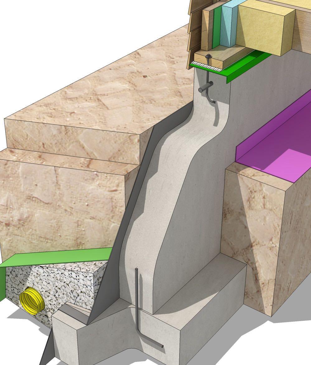
12 BASEMENT DETAILS B1 BASEMENT - CMU WALL, INTERNAL INSULATION FLOOR SLAB UNINSULATED Detail B1 - Basement - CMU wall, internal insulation, floor slab uninsulated 74 SECTION 2 - BASEMENTS

13 3D Detail B1 - Basement - CMU wall, internal insulation, floor slab uninsulated 75

14 FLOORS SECTION 3

15 F7 JOISTS AT EXTERIOR WALL, PERPENDICULAR TO WALL Detail F7 - Joists at exterior wall, perpendicular to wall 3D Detail F7 - Joists at exterior wall, perpendicular to wall 98 SECTION 3 - FLOORS
16 NOTES ON THE CODE FLOORS The following information is a partial list of requirements from the 2015 International Residential Code (IRC) - for full and detailed explanations and requirements please consult the full publication. GENERAL REQUIREMENTS (R501) Floor construction must be capable of accommodating all loads in accordance with section R301 and of transmitting resulting loads to the supporting structural elements. WOOD FLOOR FRAMING (R502) Lumber to be identified by a grade mark of an accredited lumber grading or inspection agency. Any preservative treated lumber shall be identified as required by section R DESIGN AND CONSTRUCTION Spans for floor joists must be in accordance with Tables R (1) and R (2) Floor cantilever spans not to exceed nominal depth of the wood floor joist Joists under parallel bearing partitions shall be of adequate size to support load. Bearing partitions perpendicular to joists shall not be offset from supporting girders, walls or partitions more than joist depth unless such joists are of suitable size to carry additional load. End of each joist, beam or girder shall not have less than 1 1/2 inches of bearing on wood or metal and not less than 3 inches on masonry or concrete. The bearing on masonry concrete must be direct or a sill plate of 2 inch min nominal thickness provided under the joist beam or girder. Joists shall be supported laterally at the ends by full depth header, band or rim joist or to an adjoining stud. FLOOR SHEATHING (R503) Maximum allowable spans for lumber used as floor sheathing must conform to tables R503.1, R (1) and R (2). End joints in lumber used as sub flooring shall occur over supports unless end-matched lumber is used. Wood structural panel sheathing Panels must be identified for grade, bond classification and performance category. Maximum span for structural panel used as sub-floor must conform to table R (1). 110 SECTION 3 - FLOORS
17 WALLS

18 If you are using a SIP panel, or OSB sheathing that has closed cell spray foam on the interior, a gap is recommended to allow the panels to dry to the exterior as they won t be able to dry to the interior. If your walls are sheathing with rigid foam, most sidings would require vertical furring strips. Brick veneer will always require a ventilation gap, minimum 1inch. Rainscreen gaps are always beneficial, and provide a more durable solution to external wall finish. The rain screen gap can range from 1/4 inch to 1 inch, depending on the system. The gaps are created using furring strips installed vertically directly over the studs, or using a drainage mat, which is a three dimensional plastic mesh, that allows liquid to drain down the face of the mat. The system will require weep holes or drainage openings at the bottom of the rain screen gap. Horizontal siding Horizontal siding, usually cedar, redwood or pine, is a common form of siding. Profiles are also made of composite hardboard or cement board. Figure 4.3 Horizontal wood siding Figure 4.4 Vertical wood siding Vertical wood siding Vertical wood siding is a tongue and groove or channel system where the boards are attached to sheathing or horizontal nailing strips. Vinyl siding Vinyl siding is a low maintenance alternative to the popular wood options. The siding is installed over sheathing. Wood shingle siding Shingle siding is a popular option, it is considered durable, low maintenance and can be installed painted, stained or left natural. It is often red cedar, but can also be seen as redwood or cypress. Shingles are installed over a moisture barrier to the external wall sheathing so that two layers of the shingles are always covering the wall. Figure 4.5 Vinyl siding Figure 4.6 Wood shingle siding 116 SECTION 4 - WALLS
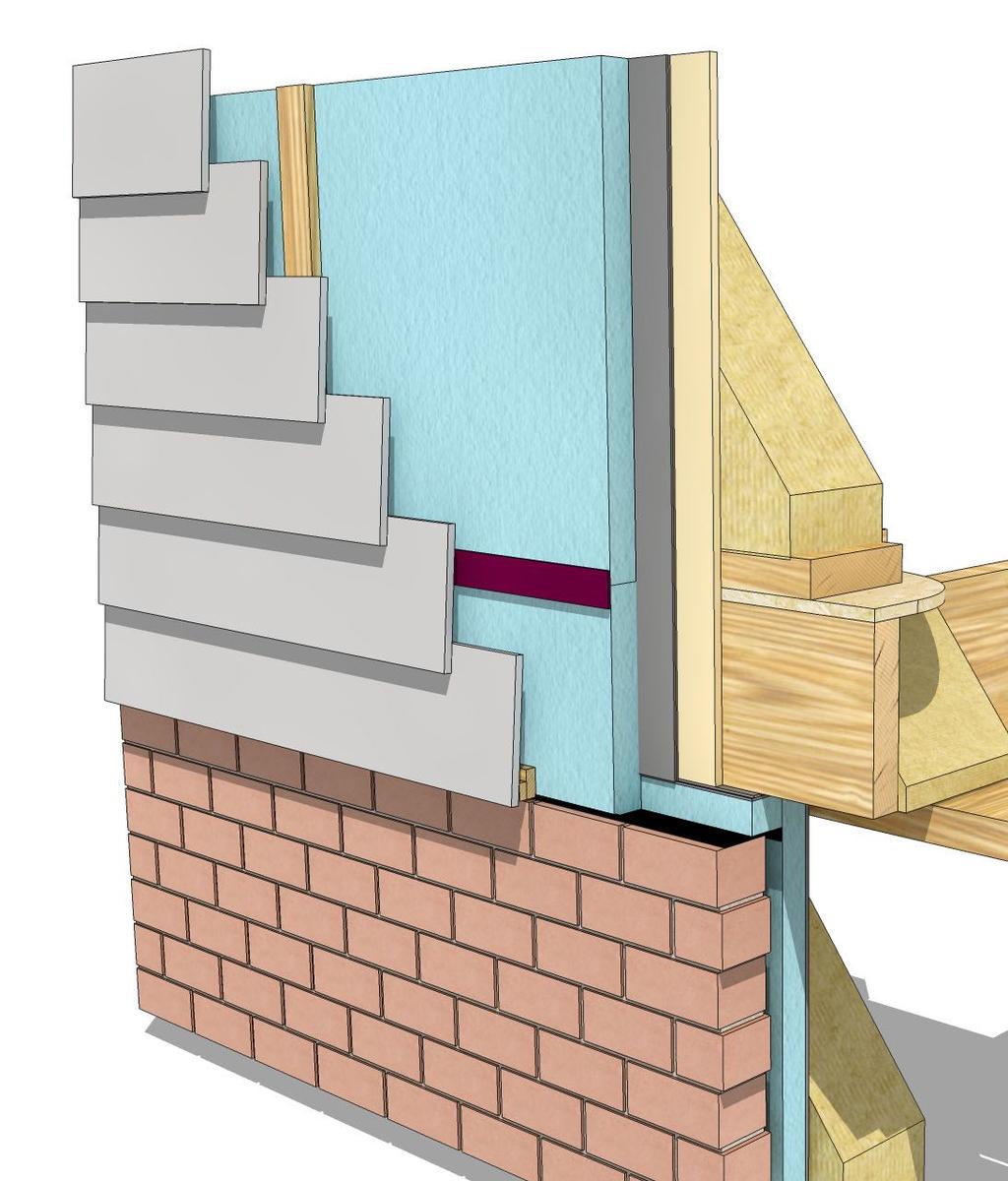
19 WALL DETAILS W1 CEMENT BOARD LAP SIDING - JUNCTION WITH FLOOR/FOUNDATION Detail W1 - Cement board lap siding - junction with floor/foundation 122 SECTION 4 - WALLS

20 3D Detail W1 - Cement board lap siding - junction with floor/foundation 123

21 ROOFS SECTION 5
22 ROOF DETAILS R1 WOOD SHINGLE ROOF - VENTED ATTIC SPACE WOOD LAP SIDING WALL Detail R1- Wood shingle roof - vented attic space - wood lap siding wall 250 SECTION 5 - ROOFS


23 3D Detail R1- Wood shingle roof - vented attic space - wood lap siding wall 251

24 R21 ASPHALT ROOF - RIDGE VENT Detail R21 - Asphalt roof - ridge vent 3D Detail R21 - Asphalt roof - ridge vent 279
25 2D Detail Index Detail G1 - Crawl space foundation, cmu wall, vented, uninsulated 18 Detail G2 - Crawl space foundation, concrete cast in place wall, vented, uninsulated 20 Detail G3- Crawl space foundation, brick veneer below mudsill, vented, uninsulated 22 Detail G4 - Crawl space foundation, brick veneer level with mudsill, vented, uninsulated 24 Detail G5 - Crawl space foundation, brick veneer with CMU, vented, uninsulated 26 Detail G6 - Crawl space foundation, CMU above grade, vented, uninsulated 28 Detail G7 - Crawl space foundation, concrete cast in place, vented, external insulation 30 Detail G8 - Crawl space foundation, brick veneer below mudsill, vented, external insulation 32 Detail G9 - Crawl space foundation, CMU, unvented, internal insulation 34 Detail G10 - Crawl space foundation, concrete cast in place, unvented, internal insulation 36 Detail G11 - Crawl space foundation, brick veneer below mudsill, unvented, internal insulation 38 Detail G12 - Crawl space foundation, brick veneer level with mudsill, unvented, internal insulation 40 Detail G13 - Crawl space foundation, CMU with brick veneer, unvented, internal insulation 42 Detail G14 - Crawl space foundation, CMU above grade, unvented, internal insulation 44 Detail G15 - Crawl space foundation, CMU, unvented, high level external insulation - for cold climate 46 Detail G16 - Slab on grade, turned down footing, external insulation 48 Detail G17 - Slab on grade, turned down footing, insulation flush with framing 50 Detail G18 - Slab on grade, deep footing, internal insulation 52 Detail G19 - Slab on grade, deep footing, insulation under slab, cold climate 54 Detail G20 - Slab on grade, deep footing, external insulation to foundation wall 56 Detail G21- Slab on grade, CMU foundation wall, brick veneer, insulation under slab 58 Detail G22- Slab on grade, CMU foundation wall, brick veneer, insulation under slab - alternative detail 60 Detail G23- Pier and grade beam, brick veneer 62 Detail G24 - Pier and grade beam, indicative siding 64 Detail B1 - Basement - CMU wall, internal insulation, floor slab uninsulated 74 Detail B2 - Basement - CMU wall, external insulation, floor slab uninsulated 76 Detail B3 - Basement - concrete wall, external insulation, floor slab uninsulated 78 Detail B4 - Basement - concrete wall, internal insulation, floor slab uninsulated 80 Detail B5 - Basement - concrete wall, internal insulation, brick veneer, floor slab uninsulated 82 Detail B6 - Basement - concrete wall, internal insulation, insulated floor slab 84 Detail B7- Basement - concrete wall, high level internal insulation, insulated floor slab 86 Detail F1 - Joist on mudsill, perpendicular to wall 92 Detail F3 - Joists flush with mudsill, perpendicular to wall 94 Detail F4- Joists below mudsill, perpendicular to wall, supported by ledger 95 Detail F5 - Joists below mudsill, parallel to wall 96 Detail F6- Joists below mudsill, perpendicular to wall, stepped wall support 97 Detail F7 - Joists at exterior wall, perpendicular to wall 98 Detail F8 - Joists at exterior wall, perpendicular to wall, alternative detail 99 Detail F9 - Joists at exterior wall, parallel to wall 100 Detail F10 - Joists at exterior wall, parallel to wall, alternative detail 101 Detail F11 - Joists at exterior wall, double rim joists, parallel to wall 102 Detail F12 - Joists at bearing wall, parallel to wall 103 Detail F13 - Joists at bearing wall, perpendicular to wall
26 Detail F14 - Joists at partition wall, parallel to wall 105 Detail F15 - Girders on mudsill, perpendicular to wall 106 Detail F16 - Girders flush with mudsill, perpendicular to wall 108 Detail W1 - Cement board lap siding - junction with floor/foundation 122 Detail W2 - Cement board lap siding - over brick veneer 124 Detail W3 - Cement board lap siding - over stone veneer 126 Detail W4 - Cement board lap siding - over stucco 128 Detail W5 - Cement board lap siding - over vertical board siding 130 Detail W6 - Cement board lap siding - window head 132 Detail W7 - Cement board lap siding - window sill 132 Detail W8 - Cement board lap siding - window jamb (plan) 132 Detail W9 - Brick veneer siding - junction with floor/foundation 134 Detail W10 - Brick veneer siding - junction with floor/foundation - additional insulation 136 Detail W11 - brick veneer - window head 138 Detail W12 - Brick veneer - window sill 138 Detail W13 - Brick veneer siding - window jamb (plan) 140 Detail W14 - Metal lap siding - junction with floor/foundation 142 Detail W15 - Metal lap siding - over brick veneer 144 Detail W16 - Metal lap siding - over stone veneer 146 Detail W17 - Metal lap siding - window head 148 Detail W18 - Metal lap siding - window sill 148 Detail W19 - Metal lap siding - window jamb (plan) 150 Detail W20 - Stone veneer - floor/foundation junction 152 Detail W21 - Stone veneer - floor/foundation junction - additional insulation 154 Detail W22 - Stone veneer - window head 156 Detail W23 - Stone veneer - window sill 156 Detail W24 - Stone veneer - window jamb (plan) 158 Detail W25 - EIFS (exterior insulation and finish system) - floor/foundation junction 160 Detail W26 - EIFS (exterior insulation and finish system) - over brick veneer 162 Detail W27 - EIFS (exterior insulation and finish system) - over stone veneer 164 Detail W28 - EIFS (exterior insulation and finish system) - over wood lap siding 166 Detail W29 - EIFS (exterior insulation and finish system) - over vertical board siding 168 Detail W30 - EIFS (exterior insulation and finish system) - window head 170 Detail W31 - EIFS (exterior insulation and finish system) - window sill 170 Detail W32 - EIFS (exterior insulation and finish system) - window jamb (plan) 172 Detail W33 - Vertical board siding - floor/foundation junction 174 Detail W34 - Vertical board siding - drainage mat 176 Detail W35 - Vertical board siding - over brick veneer 178 Detail W36 - Vertical board siding - over stone veneer 180 Detail W37 - Vertical board siding - over wood lap siding 182 Detail W38 - Vertical board siding - over stucco 184 Detail W39 - Vertical board siding - window head 186 Detail W40 - Vertical board siding - window sill 186 Detail W41 - Vertical board siding - window jamb (plan) 188 Detail W42 - Vinyl lap siding - floor/foundation junction 190 Detail W43 - Vinyl lap siding - over brick veneer 192 Detail W44 - Vinyl lap siding - over stone veneer 194 Detail W45 - Vinyl lap siding - window head 196 Detail W46 - Vinyl lap siding - window sill 196 Detail W47 - Vinyl lap siding - window jamb (plan)
27 Detail W48 - Wood lap siding - floor/foundation junction 200 Detail W49 - Wood lap siding - over brick veneer 202 Detail W50 - Wood lap siding - over stone veneer 204 Detail W51 - Wood lap siding - window head 206 Detail W52 - Wood lap siding - window sill 206 Detail W53 - Wood lap siding - window jamb (plan) 208 Detail W54 - Wood shingle siding - floor/foundation junction 210 Detail W55 - Wood shingle siding - over brick veneer 212 Detail W56 - Wood shingle siding - over stone veneer 214 Detail W57 - Wood shingle siding - window head 216 Detail W58 - Wood shingle siding - window sill 216 Detail W59 - Wood shingle siding - window jamb (plan) 218 Detail W60 - Stucco siding - floor/foundation junction 220 Detail W61 - Stucco siding - over brick veneer 222 Detail W62 - Stucco siding - over wood lap siding 224 Detail W63 - Stucco siding - over vertical board siding 226 Detail W64 - Stucco siding - window head 228 Detail W65 - Stucco siding - window sill 228 Detail W66 - Stucco siding - window jamb (plan) 230 Detail D1 - Cement board lap siding - door head jamb 232 Detail D2 - Cement board lap siding - door sill 233 Detail D3 - Cement board lap siding - door jamb (plan) 234 Detail D4 - General opening - door sill / threshold 235 Detail D5 - General openings - door sill/threshold with pan flashing and decking 236 Detail D6 - General opening - door head jamb 237 Detail D7 - General opening - door side jamb (plan) 237 Detail R1- Wood shingle roof - vented attic space - wood lap siding wall 250 Detail R2- Wood shingle roof - vented attic space - cement board siding wall 252 Detail R3- Wood shingle roof - vented attic space - brick veneer 253 Detail R4- Wood shingle roof - vented attic space - metal lap siding wall 254 Detail R5- Wood shingle roof - vented attic space - stone veneer wall 255 Detail R6- Wood shingle roof - vented attic space - EIFS siding wall 256 Detail R7- Wood shingle roof - vented attic space - vertical board siding wall 257 Detail R8- Wood shingle roof - vented attic space - stucco siding wall 258 Detail R9- Wood shingle roof - vented attic space - wood shingle siding wall 259 Detail R10 - Asphalt roof - vented attic space - wood shingle siding wall 260 Detail R11 - Concrete tile roof - vented attic space - wood shingle siding wall 261 Detail R12 - Metal roof - vented attic space - cement board siding wall 262 Detail R13 - Tile roof - vented attic space - cement board siding wall 264 Detail R14 - Asphalt roof - vented roof deck - wood shingle siding wall 266 Detail R15 - Asphalt roof - unvented roof - wood lap siding wall 268 Detail R16 - Asphalt roof, raised plate - vented attic space- wood shingle siding wall 270 Detail R17 - Asphalt roof, cathedral ceiling - vented roof deck - wood shingle siding wall 272 Detail R18 - Asphalt roof, cathedral ceiling - unvented roof - wood shingle siding wall 274 Detail R19- Wood shingle roof - raised heel truss - vented attic space - vertical board siding wall 276 Detail R20 - Wood shingle roof - ridge vent 278 Detail R21 - Asphalt roof - ridge vent 279 Detail R22 - Metal roof - ridge vent 280 Detail R23 - Tile roof - ridge vent
28 Detail R24- Asphalt roof - exposed eave 282 Detail R25- Asphalt roof - abbreviated eave 284 Detail R26- Tile roof - soffited eave 286 Detail R27- Asphalt roof - exposed rake 288 Detail R28- Shingle roof - abbreviated rake 290 Detail R29 - Tile roof - boxed in rake

29 RESIDENTIAL CONSTRUCTION DETAILS US VERSION From First In Architecture