Mounting instructions. novotegra for folded seam roof
|
|
|
- Lucas Stafford
- 5 years ago
- Views:
Transcription


1 Mounting instructions novotegra for folded seam roof I
2 TABLE OF CONTENTS 1 Notes Maintenance of the mounting system novotegra for folded seam roof System components, tools and work equipment Required for installation Installation system components installation variants Installation system components optional Installing the substructure Clamp assembly Installing the rails Installing the module Mounting versions Warranty / product liability and disclaimer II


3 1 Notes Safety information. Mounting tasks may only be carried out by qualified and competent persons. During the work protective clothing in accordance with the relevant national regulations and guidelines must be worn. Mounting must be carried out by at least two persons to ensure help in case of an accident. All relevant national and locally applicable health and safety regulations, accident prevention regulations, standards, construction standards and environmental protection regulations as well as all regulations of the employers liability insurance associations must be complied with. The national regulations for working at height / on the roof must be complied with. Electrical work must be carried out in compliance with the national and locally applicable standards and guidelines and the safety rules for electrical work. Earthing / equipotential bonding of the mounting system must be carried out in accordance with the national and locally applicable standards and guidelines. Classification into hazard classes To alert the user of potential danger situations the hazard classes analogous to ANSI Z 535 are used. The hazard class describes the risk if the safety information is not observed. Warning symbol with signal word Hazard class analogous to ANSI Z 535 DANGER! describes an immediate danger. If it is not avoided, death or serious injury will result. WARNING! describes a potential danger. If it is not avoided, death or serious injury might result. CAUTION! describes a potential danger. If it is not avoided, light or minor injury might result. NOTE! describes a potentially harmful situation. If it is not avoided, the plant or objects in its vicinity might be damaged. General information After receipt the goods must be inspected for completeness using the accompanying delivery note. BayWa r.e. Solar Energy Systems GmbH does not accept the costs, nor can we guarantee subsequent express deliveries if missing material is only noticed during mounting. Since our mounting systems are subject to continuous development, mounting processes or components may change. Therefore, please check the current status of the mounting instructions on our website prior to mounting. We are also happy to send you current versions upon request. The mounting system is suitable for the attachment of PV modules with standard market dimensions. The maximum permissible module width is 1.34 m. The usability of the mounting system for the respective project must be checked for each individual case on the basis of the roof cover / roof construction present. The roof cover / roof construction must meet the requirements of the mounting system with regard to load bearing capacity, support structure and condition. 1
4 Requirements for the material of the roof construction or roof cover: Wooden components (rafters/purlins): min. strength class C24, no fungus infection or rot Tensile strength Rm, min for trapezoidal metal: steel 360 N/mm²; aluminium 195 N/mm² The load bearing capacity of the roof / roof construction (rafters, purlins, trapezoidal metal, number of adhesive points, folded seams, etc.) must be checked by the user or a check be commissioned. Physical building aspects concerning insulation penetrations (e.g. condensation) must be taken into account by the user. Notes on mounting The components of the novotegra mounting system are intended exclusively for the attachment of PV modules. Dependent on the roof type of the building the designated mounting system components must be used. A condition for the intended use of the novotegra mounting system is the mandatory compliance with the specifications in these instructions regarding safety information and mounting. In case of unintended use and non-compliance with the safety information and mounting instructions and non-utilisation of the corresponding mounting components or use of third party components not belonging to the mounting system any warranty and liability claims against the manufacturer are voided. The user is liable for damage and resulting consequential damage to other components, such as PV modules, or the building as well as personal injury. The user must read the mounting instructions prior to mounting. Unresolved issues must be clarified with the manufacturer prior to mounting. The mounting sequence in these instructions must be adhered to. It must be ensured that a copy of the mounting instructions is accessible in the immediate vicinity of the work on site. The mounting specifications (module load, attachment, clamping areas etc.) of the module manufacturer must be observed and complied with. Prior to mounting the mounting system must be statically calculated with the loads to be assumed for the building project in accordance with the national standards. Information relevant to mounting (e.g. roof hook distance, lengths of bolts, overhang and protrusions) must be determined by the static calculation using the design software Solar-Planit.de. The permissible roof inclination for the use of the mounting system in accordance with these mounting instructions is 0 to 60 degrees. For each module two module support rails must be fitted symmetrically under the modules for the even load introduction to the substructure. Alternatively the system can be installed using insertion rails. The specified tightening torques must be adhered to and checked randomly on site. Notes on static calculations The mounting system must generally be statically calculated for each individual project using the design software Solar-planit.de. The static calculation only determines the load bearing capacity of the novotegra mounting system and also takes account of the attachment to the building (rafters, purlins, trapezoidal metal etc.). The load transfer within the building is not considered (customer static calculations). The load bearing capacity of the mounting system components is determined on the basis of the planned module layout and the underlying roof information (project data recording). Deviations from the planning on site may lead to different results. The load assumptions (load and roof division) are country-specific in accordance with the specifications of the Eurocode load standards. The determination of the loads to be assumed for Switzerland is in accordance with SIA 261. The modules may not be fitted above the gable end, ridge and eaves (increased wind load). At the ridge the modules may be fitted up to max. a theoretical horizontal line with the ridge tile and perfectly flush with the gable end. In the eaves area the modules may reach to max. the end of the roof cover due to loads. 2

5 In case of an exposed building position (with wind load e.g. at the edge of a slope) or snow accumulation (e.g. dormer or catchment grill) the specifications of the Eurocode load standards or SIA 261 (Switzerland) must be taken into account by the user within his own responsibility. The design software does not consider these cases. The static calculation of the mounting system is based on the symmetrical placement of the modules on the mounting rails at the longitudinal side of the modules for even load transfer into the substructure. For the insertion system a cross rail arrangement is expected for even load transfer. The results calculated with the design software, such as distances of the fasteners (e.g. roof hooks, stock screws, saddle clamps etc.), rail lengths and number of fasteners (e.g. direct attachment on the trapezoidal metal), overhang (e.g. rail and roof hook protrusions) and the other calculation notes must be considered and complied with. novotegra has been tested and certified by TÜV Rheinland: 2 Maintenance of the mounting system The mounting system must be checked for stability and operation at regular intervals during the system maintenance. In addition to the visual inspection of the components and the roof cover for damage we recommend a random inspection of the connections. Removal is possible in reverse order in the work steps mentioned below. The maintenance work must be carried out by a specialist company with proven experience in electrical systems and work on mounting systems. 3 novotegra for folded seam roof These mounting instructions describe the design of the substructure on folded seam roof (standing and round seam roofs) or profile sheet roofs (Zambelli RibRoof 465 and 500 or Domico GBS). The seam and profile sheet clamps must be attached to every seam in the area of the module array and are suitable for roof coverings made from steel and copper sheet, titanium zinc, aluminium and stainless steel. Depending on the thickness of the sheet and the roofing material, A2SS saddles may need to be installed beneath the clamps, depending on the clamp. 3


6 4 System components, tools and work equipment 4.1 Required for installation Image Tool Component* Product group Seam/profile sheet clamp set Material: A2SS and aluminium Tool: Bit setscrew Open-end wrench 13 mm Roof fixation C-rail Material: Aluminium Tool: Special socket AF 18 deep Rail connector set C Material: Aluminium and A2SS Tool: Special socket AF 18 deep Middle clamp sets C Material: Aluminium, Aluminium cast and A2SS Tool: Socket bit AF 8 End clamp sets C Material: Aluminium, Aluminium cast and A2SS Tool: Socket bit AF 8 Module slip guard Material: A2SS Rail Rail connectors and expansion joint Module attachment Module attachment Module protection and rail top cover * The components vary depending on the requirements of the roof, the structural analysis and the choice of components and may deviate from the images above. Image Work equipment Cordless screwdriver Torque key up to at least 50 Nm Torque key up to at least 10 Nm Use for tool Torx TX bit 40 Socket AF 8 Special socket AF 18 deep Socket AF 8 Use Clamp mounting component attachments Rail mounting Clamp mounting Chopsaw --- Rail section 4


, system expansion (e.g. using floating bearings) or module arrangement (e.")


7 4.2 Installation system components installation variants Image Tool Component** Product group Cross rail connector set C Material: Cast aluminium and A2SS Tool: Special socket AF 18 deep Rail connectors and expansion joint Expansion joint* Material: Aluminium and A2SS Tool: Special socket AF 18 deep Rail connectors and expansion joint Slip guard for landscape mounting Material: Aluminium and A2SS Tool: Special socket AF 18 deep Module protection and rail top cover ** Required components depending on construction of substructure (e.g. cross rail configuration), system expansion (e.g. using floating bearings) or module arrangement (e.g. horizontal module installation). 4.3 Installation system components optional Image Tool Component*** Product group End cap C-rail Material: Aluminium and A2SS Tool: Special socket AF 18 deep Module protection and rail top cover Top cover C-rail 2,000 mm Material: Aluminium Module protection and rail top cover Grounding connector set AF 18 Material: A2SS Tool: Special socket AF 18 deep Accessories and optional components Self-locking cable ties Cable protection Cable clip d = 10 mm Cable protection *** Optionally available installation system components, e.g. for improving the aesthetics of the system, cable routing or earthing of the installation system. 5
 determined, taking the structural analysis into account. The individual installation steps for vertical module installation are described below.")


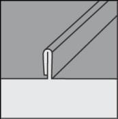
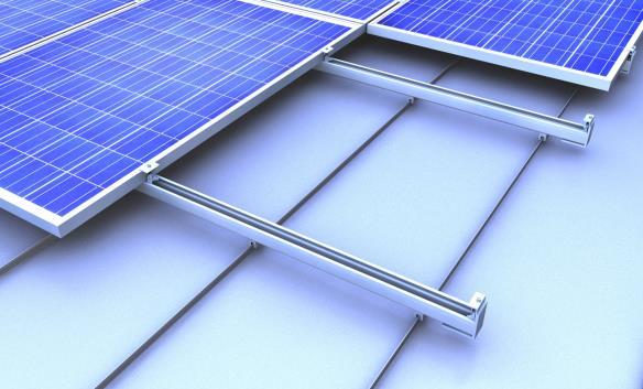
8 5 Installing the substructure Prior to installation, the module array must be measured out on the roof and the position of the fastening equipment (e.g. roof hooks, hanger bolts, seam clamps, etc.) determined, taking the structural analysis into account. The individual installation steps for vertical module installation are described below. References are made to installation variants (MV) for the various design possibilities. The associated work steps are described at the end. 5.1 Clamp assembly Marking out the clamp axis Upper Rail axis The clamps must be installed centred under the C rails. To do this, first mark out the axis on the roof covering or mark it with the cord. Two rail axes must be provided for each row of modules. Lower Scaffolding must be constructed in accordance with the relevant regulations. Attaching the clamps Place the clamp on the seam and fasten using the set screw. The clamps must not be installed on or near the metal retainers. The image shows the clamp for standing seam roofs. Clamps as per MV 1 and MV 2 are available depending on the roof covering. Tightening torque for setscrew Nm 5.2 Installing the rails Installing the rail Place the C-rail on the clamp and tighten the rail using the locking bolt. If installing in a cross rail configuration, the upper rail is fastened using cross rail connectors (MV 3). Tightening torque for locking bolts: 50 Nm. 6


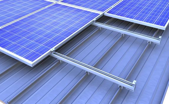
9 Connecting the rails 2 bolts Join the rail ends flush, apply the rail connector centred and connect it to the rail using the mounting screws included in the set. The connector and number of screws depend on the rail. Maximum uninterrupted rail length 3.06 m, then install expansion joint or disconnect the rail (MV 4). Tightening torque for locking bolts: 50 Nm. The accident prevention regulations must be complied with when cutting to size. 5.3 Installing the module Securing the module Prior to mounting the modules the slip guards must be fitted to the frame holes above the top and bottom rail position (MV 5). Clamping the module The modules must then be attached to the rails using end clamps and middle clamps. Installing the end and middle clamps Insert the middle clamps or end clamps at the clamping position from above into the rail chamber. Then turn the rail nut in the rail and push the module clamps towards the module frame. 7

.")
 - Place the clamp in position - Fasten the clamp with the setscrew - Tightening")


 - Place the clamp in position - Fasten the clamp with the")
10 Space requirement for end and middle clamps 13 mm 12 mm End clamp mounting flush with the rail end possible. Push the modules fully to the rail nuts of the middle clamps. Tightening torque for middle clamps: 10 Nm, tightening torque for end clamps: 8 Nm. 5.4 Mounting versions Explanation of the installation variants depending on the roof construction or design variants (e.g. round seam clamps or cross rail configuration). MV 1 Clamp set for copper roof covering A2SS saddle Standing seam clamp set for copper: - For copper standing seam roofs - Install the A2SS saddle (image left) - Place the clamp in position - Fasten the clamp with the setscrew - Tightening torque 20 Nm - The clamps must not be installed on or near the metal retainers. MV 2 Clamp set variants A2SS saddle Round seam clamp set: - For Kalzip roof coverings - Place the clamp in position - Push in the clamp insert - Fasten the clamp with the setscrew - Tightening torque Nm - The clamps must not be installed on or near the metal retainers. Profile sheet clamp set ZD: - For Zambelli RibRoof 465 and Domico GBS roof coverings - Material thickness = 0.7 mm requires installation of an A2SS saddle (image right) - Place the clamp in position - Fasten the clamp with the setscrew on both sides - Tightening torque for material thickness > 0.7 mm = 15 Nm - Tightening torque for material thickness = 0.7 mm = 17 Nm - The clamps must not be installed on or near the metal retainers. 8


 and screw it tight as described above.")

11 Profile sheet clamp set Z: - For Zambelli RibRoof 500 roof coverings - Place the clamp in position and click into place - Fasten the clamp with both screws (open-end wrench 13 mm) - Tightening torque 25 Nm - The clamps must not be installed on or near the metal retainers. MV 3 Mounting Cross rail connector 1 Cross rail mounting: Insert the Cross rail connector sets C M14 from above into the rail groove (1) and rotate by 90 (2). 2 Cross rail connector set C M14 tightening torque 40 Nm. MV 4 Rail connectors MV 4.1 Mounting rail connector set C47 S mm Push the rail connector set (1) half way into one of the rails to be connected (2) and secure it there with a drilling screw each on both sides approx. 20 mm from the rail end. Next push the other rail completely onto the rail connector set until both rail ends make contact (3) and screw it tight as described above. Maximum uninterrupted rail length 3.06 m, then install expansion joint. 3 The accident prevention regulations must be complied with during cutting to size MV 4.2 Mounting expansion joints for C-rails Fixed side Gap between C rails Place the rail ends on the gap, put the rail connector in place and connect to the rail using the fastening screws on the fixed and moving sides. The screws on the fixed side must be tightened firmly. The screws on the moving side are painted red and must be loosened again after tightening (approx. ½ turn). Plan proper expansion joint after common rail lengths. Moving side Tightening torque for locking bolt on fixed side: 50 Nm. Distance between adjacent rail ends = 20 mm. 9


12 MV 5 Slip guard MV 5.1 Modules with box frame Thin metal screw Push the nut over the screw and screw the thin metal screw into the module frame without predrilling. M6 nut Reverse side Module frame The thin metal screw must not be overtightened. MV 5.2 Module mounting in landscape 5 mm gap Screw the slip guard to the rail end with approx. 5 mm gap using mounting screw and self-locking nut. Self-locking nut tightening torque 50 Nm. 10
13 6 Warranty / product liability and disclaimer In addition to the aforementioned regulations and safety instructions, the installation company must observe the valid regulations and standard engineering practice. The installation company is responsible for dimensioning the novotegra installation system. The installation company is responsible for connecting the interfaces between the installation system and the building. This also includes the seal tightness of the building envelope. On flat roofs, the installation company is responsible for the on-site assessment of the roof seal with regard to the sealing membrane material, durability, ageing, compatibility with other materials, general state of the roof seal and the need for a separation membrane between the roof seal and the installation system. The installation company must take the required and necessary measures and/or precautions for protecting the roof seal for the installation of the PV system substructure, if necessary with the involvement of a specialist. BayWa r.e. Solar Energy Systems GmbH shall bear no liability for incorrect or insufficient measures and precautions for protecting the roof seal. The installation company is responsible for the on-site testing of the coefficient of friction used in the calculation for verification of the anti-slide protection for PV systems on flat roofs. Coefficients of friction calculated on site can be taken into account and must be provided to BayWa r.e. Solar Energy Systems GmbH for the calculation. BayWa r.e. Solar Energy Systems GmbH shall assume no guarantee for the correctness of the assumed values and shall bear no liability in the event of damages caused as a result of the use of incorrect values. The instructions of the module, cable and inverter manufacturers must be observed. In the event of instructions that contradict those in this installation manual, be sure to contact your BayWa r.e. Solar Energy Systems GmbH sales team prior to installation or else the relevant manufacturer for components not supplied by BayWa r.e. Solar Energy Systems GmbH. Local conditions are not always sufficiently well known by our sales representatives when preparing quotations for novotegra. This may result in deviations from the quoted parts quantities during installation. These deviations mostly relate to the quantity of fastening material to the building envelope (such as roof hooks). In this case, the additionally required components must be installed in accordance with the dimensioning. BayWa r.e. Solar Energy Systems GmbH shall bear no liability for incorrectly or incompletely filled-in data survey sheets. Completely filled-in and error-free data survey sheets are essential for correct dimensioning. The information in the installation manual, the warranty conditions and the disclaimer information must be observed. 11
14 NOTES: 12
15 NOTES: 13


16 BayWa r.e. Solar Energy Systems GmbH Eisenbahnstraße 150 D Tübingen Phone Fax solarenergysystems.baywa-re.com Sales Office Tübingen Sales Office Munich Sales Office Nuremberg Welzenwiler Straße 5 Beethovenplatz 4 Wiesentalstraße D Tübingen D München D Nürnberg Phone Phone Phone Fax Fax Fax tue.solarenergysystems@baywa-re.com mue.solarenergysystems@baywa-re.com nue.solarenergysystems@baywa-re.com Sales Office Duisburg Sales Office Brunswick BayWa r.e. solar systemer ApS Aakerfährstraße 40 Heinrich-Büssing-Ring 25 Kullinggade 31E D Duisburg D Braunschweig DK-5700 Svendborg Phone Phone Phone Fax Fax Fax dui.solarenergysystems@baywa-re.com bsg.solarenergysystems@baywa-re.com solarsystemer@baywa-re.com Subject to errors and amendments. Date: July 2017/ASC, version 3.1 Copyright BayWa r.e. Solar Energy Systems GmbH 14