Welcome to this continuing education seminar. This is the first of two parts of the High- Performance Building series.
|
|
|
- Beatrice Snow
- 5 years ago
- Views:
Transcription
1 Welcome to this continuing education seminar. This is the first of two parts of the High- Performance Building series. 1
2
3 3
4
5
6 6
7 7
8 8

9 An enclosure s basic function is to separate the outside from the inside. In old buildings, all functions were performed by a single layer. In new buildings, control functions are separated into different layers. This means we can now optimize the characteristics and performance of each of the control layers. 9
10 This is the perfect wall from a building science perspective. It describes how to choose and arrange the layers to accomplish the desired functions. Every building must perform three main functions in this order of importance: 1. Support 2. Control continuity, including: -Rain control -Air control -Thermal control - Vapor control 3. The finish -Interior and exterior Control functions are listed in order of importance. The perfect wall is a theoretical construct that provides a reference point for enclosure design decisions. Each layer should be identifiable in a drawing and continuous around the building. 10

11 Even if the concept is named the perfect wall, it should be applied continuously on every assembly that is involved in the building enclosure, including walls, roofs, floors, and all transition details. The physics don t change from wall to roof to floor. Continuity is the key to performance. 11
12 The perfect wall concept contains different control layers. This session will cover the air-control layer. A good design should require performance standards for the building, then drill them down to suitable systems, selecting products that support design and performance goals. 12
13 Air control is critical for all climates: it controls condensation in the summer as well as winter, helping to prevent energy waste and structural degradation. An airtight building can be better climatized for either heating or cooling. This will have an immediate impact on the comfort for all occupants. The building design enclosure itself can t be too tight, but airtight buildings must be mechanically ventilated to ensure fresh air. 13
14 Air-barrier requirements (in order of importance): -Continuous -Strong -Stiff -Durable - and Air Impermeable The reason for this order is that an air-impermeable component will not be effective without continuity. An air-barrier system must meet several requirements, but continuity is both the most important and the most challenging requirement to achieve in a modern steel, wood, or concrete building. 14
15 This example represents typical issues when planning continuity and airtightness. A standard approach might be to use interior polyethylene as an air barrier. Complex shapes and designs make continuity a challenge when attempting an interior air barrier. For commercial buildings, sometimes the only solution is an exterior air-barrier solution.

16 The interior air-barrier approach is typical for residential buildings. The detailing for continuity is considerably more difficult because of penetrations and transitions. The exterior approach involves fewer penetration details and is easier to inspect for discontinuity. A fully supported (rigid) air barrier installed on the outside of the structure is the most likely approach to meet the air-barrier system performance criteria. 16
17 The pumping effect can have an impact on energy and durability in the wall by drawing conditioned air into the wall system, even if installed in a continuous, airtight manner, which risks condensation. This effect can occur even with relatively minor movement. Therefore, strength and stiffness are prerequisites for an air-barrier system. 17
18 One part of the wall is under pressure and one part is under suction. This can introduce air movement into the cavity, especially with porous materials or unintentional openings. This wind-washing effect can reduce thermal R-values and also lead to condensation. It can be avoided with an exterior air-barrier system. 18

19 This is why air barriers must be thought of as a system, not a product. Even though air movement into and out of the building is controlled, uncontrolled air movement through the stud space can lead to higher energy consumption, reduced R-value of insulation, moisture risk, and uncomfortable occupants. 19
20 20

21 Air moves more moisture vapor than diffusion. Air movement can have an immediate or short-term impact on moisture movement. Because diffusion is slow, we are concerned with long-term moisture gradients. Since air can move a much greater quantity of moisture than vapor diffusion (in all climates), control of air flow is critical to the durability of a building enclosure. 21
22 22
23 23
24 The requirements for airtightness are changing: -Improved energy performance requires better airtightness in commercial buildings. -Comfort and indoor air quality expectations are changing. -Thermal and air control impact occupant comfort -Mechanical system design has improved In recognition of the benefits, building code requirements are changing to require increased airtightness. 24

25 There are different requirements for the air barrier, the system components, as well as for the entire building. The requirement for the materials is at 0.2 liters per second per square meters at 75 Pascal pressure differential. The requirement for components is 0.2 liters per second per square meters at 75 Pascal pressure differential. The requirement for the building is 2.0 liters per second per square meters at 75 Pascal pressure differential. The focus is on the performance of the whole building, not on the performance qualities of the individual materials.

26 Final airtightness of a building depends on the airtightness of many critical designs in the building enclosure design, including windows, structural penetrations (such as balconies), and mechanical penetrations. Each of these details can be improved through careful attention to continuity during the design phase and quality control during construction. Increased airtightness is not just a specification change. 26

27 The perfect approach means the details, like transitions between wall and roof assemblies, need attention and someone clearly responsible. 27

28 Red circles represent critical detail areas that could be areas of typical failure. The blue dotted line represents the plane many architects draw in detail. If it isn t made clear in the drawing what is to be done by the contractor at each of these critical detail areas, then the decision will be made by the contractor, if at all, sacrificing critical continuity. Every detail needs to be addressed. 28
29 The most common details are windows, which most every wall has. 29

30 The window must be tied into the air-barrier system to ensure airtightness. Follow the line of the air barrier and note the window connection to the air-barrier plane. 30

31 Critical points with window detailing are the corners. Prefabricated corners can be easier to install and help ensure air and water tightness. It is also critical to use, even in a vapor permeable system, vapor impermeable materials at the window sill where standing water is a risk. 31

32 The window should be fully integrated into the airtight system. The window is actually part of the air-barrier system. Therefore, it is important to connect the air barrier on the interior side of the window sill behind the bulk water exit point of the window. 32

33 There are other penetrations beyond windows and doors, like balconies, exposed slab edges, etc. Each must be detailed to maintain continuity. 33

34 A balcony is always a huge thermal bridge unless it is installed thermally broken. 34

35 The detail drawing of a thermally broken balcony installation. Continuous slabs that cantilever out to balconies and are not thermally broken act as heat sinks that conduct heat from the interior to the exterior. In this detail, the air barrier is made continuous through the wall section. 35

36 Every penetration should be detailed and addressed properly. A flexible material for pipe penetrations is an easy solution to seal pipes and maintain continuity. Note here that sequence is important and ought to be specified. 36
37 37
38 Testing verifies that the construction meets the desired performance criteria and allows remediation before the final construction or occupancy. 38
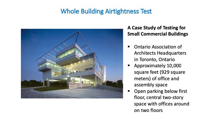
39 A quality assurance plan includes the proper design of the airtight system, its inspection, and testing. The design should include performance targets and the choice of materials and assemblies that need to be airtight. The inspection should confirm the chosen materials and systems as well as the assembly sequences. The testing of a mockup assembly is common for midsize and large buildings. A whole building test is common for smaller and midsize buildings. 39
40 The U.S. Army Corps of Engineers Air Leakage Test Protocol is an excellent reference for understanding the quality control requirements at the design, construction, and testing stages. 40
41 41
42 The preparation includes sealing all mechanical ventilation systems and penetrations that exchange air through the enclosure. 42
43 All mechanical openings were closed for the testing. 43
44 Like exterior, all interior intentional mechanical openings are closed. Logically, this should leave only unintentional openings still open. These are otherwise known as leaks. 44

45 All interior doors are wedged open to create one interior connected space. 45

46 Fans provide fixed air flow and air pressure. The difference between inside and outside pressure is measured. Air flow is measured. 46

47 Air is blown out. The total volume of air leakage from any point is measured. 47

48 Tests for commercial buildings are done at 75 Pascal, which represents the high end of pressures a building will experience. Fans are computer controlled. Dots and line represents the gradual ramping up of pressure to 75 Pascal. The resulting graph is characteristic of a particular building. Results at each pressure level are recorded, although the actual test requirement is at 75 Pascal. The above column lists air flow. The lower chart converts air flow to leakage rate (l/s/m 2 ) in turn converted to cfm/ft 2. This building passes, but if it didn t, remediation would be carried out. This test has diagnostic value. In a depressurized building, leak points can be felt by hand. 48
. Air flow jumps 40 percent.")
49 With the ASTM test complete, other diagnostics can be done. The fan is left to run at 75 Pascal. Each intentional opening is unsealed to measure its contribution to air flow. Row 1: Building is fully sealed Row 2: Small vents opened Row 3: Big air return opened (the one in which the man was standing). Air flow jumps 40 percent. This means the mechanical system is leaky, though the enclosure is tight. A damper in the system was supposed to be closed when not operational, but this indicates that they were open. 49
.")
50 Infrared photography was done at the same time (at night). The weather was cold. White indicates a cool area. Picture 1: Soffit area. Upper left is the mechanical room where air intakes are located. White line at soffit wall conjunction indicates connection not made and there is air leakage there. Picture 2: Wrapped rooftop mechanical vent (shown wrapped in earlier photo). Upper vent shows airtight. White base shows air leakage that extends under pavers. Picture 3: Vent in parking area. Leaky around vent but is an intentional opening so it was not unexpected. Leak at soffit/wall connection again. Picture 4: Another rooftop vent. 50
51 Whole Building Test Summary The enclosure should be designed to be tested. The construction should be sequenced according to the testing. Mockup testing should be done with all parties present and explained. If a target is prescribed, test as early as is practical. Testing should be made early and before air-barrier system is covered by other layers to enable repair. 51
52 52
53 This concludes the American Institute of Architects Continuing Education Systems Course. Thank you for completing this educational course by Dörken Systems. We re the first to have health product declaration (HPD) v2.0 or HPD with LEED v4 for our air-barrier systems. We re the first air- and moisture-barrier manufacturer to provide files for AutoDesk Revit. Our data is available on BSD SpecLink -E and Avitru MasterSpec software platforms. 53