STRUCTURAL ANALYSIS. PSDS s.r.o. IČ: TRABANTSKÁ 673/18, PRAHA 9. for building permit. March 2012 NUMBER OF PAGES 15
|
|
|
- Allison Mosley
- 5 years ago
- Views:
Transcription
1 2012 CONSTRUCTION DEGREE for building permit STRUCTURAL ANALYSIS March 2012 PERSON RESPONSIBLE Ing. Jiří Surovec NUMBER OF PAGES 15 PSDS s.r.o. IČ: TRABANTSKÁ 673/18, PRAHA 9 ( GSM: * psds@psds.cz
2 CONTENT 1. Materials and works cited Identification data Structure description Structural analysis Load Load on roads Load of railway transport Material characteristics Design procedure MKP analysis (analysis by means of the method of finite elements) Bearing capacity of the extended belt Results Deformation Tension Extended belt assessment Assembly schedule Conclusion cable trench cover plate PVC and PE pipes Page 2/15
![1. MATERIALS AND WORKS CITED [1] Drawing documentation of the pit's shape [2] ČSN EN 124: Gully tops and manhole tops for vehicular and pedestrian areas [3] ČSN EN 1990: Basis of structural design](/docs-images/94/121770112/images/3-0.jpg "[4] ČSN EN 1991-2: Traffic loads on bridges [5] ČSN 73 1001: Subsoil under shallow foundations [6] Decree SŽDC S3 \"Railways superstructure\" [7] ČSN EN 10080: Steel for the reinforcement of concrete 2.")
3 1. MATERIALS AND WORKS CITED [1] Drawing documentation of the pit's shape [2] ČSN EN 124: Gully tops and manhole tops for vehicular and pedestrian areas [3] ČSN EN 1990: Basis of structural design [4] ČSN EN : Traffic loads on bridges [5] ČSN : Subsoil under shallow foundations [6] Decree SŽDC S3 "Railways superstructure" [7] ČSN EN 10080: Steel for the reinforcement of concrete 2. IDENTIFICATION DATA TYPE OF CELLAR CLIENT CWS s.r.o. Tovární 1378/ Ústí nad Labem CONTRACTOR Ing. Jiří Surovec PSDS s.r.o. IČ: Trabantská 673/ Praha 9 PERSON RESPONSIBLE Ing. Jiří Surovec, Ph.D. Authorisation: authorised technician for statics and dynamics of constructions and for transportation constructions (AO ) cable trench cover plate PVC and PE pipes Page 3/15
4 3. STRUCTURE DESCRIPTION The subject of the assessment is the polyethylene cable cellar with external dimensions at the bottom of mm and the base height of 800 mm. The height of the pit can be adjusted by means of additional units with height of 280 mm up to the total height of 1920 mm. The cellar is designed to be installed bellow ground, so the loads are appropriate for roads class A to D in compliance with ČSN EN 124 and for railway transport for the load model 71 in compliance with ČSN EN The walls of the cellar have constant width of 12 mm and in the mm grid are reinforced by ribs with thickness of 12.5 to 14 mm. The ribs are reinforced towards the upper frame bearing the cover. The cellar does not have a bottom. The forces from the cover load will not be primarily transferred via the braces of the cellar walls, but by the bearing concrete ring. Fig STRUCTURAL ANALYSIS 4.1. LOAD LOAD ON ROADS In compliance with [2] four types of loads are considered: A 15 for surfaces used exclusively by pedestrians and cyclists B 125 for sidewalks, pedestrian zones and similar areas, zones for pulling over and parking of cars, even in floors C 250 for gratings placed in the area of drainage strips of roads D 400 for roads, hard shoulders and parking areas accessible for all vehicles cable trench cover plate PVC and PE pipes Page 4/15
5 Load as specified by the requirements of the given class acts on the surface of the road in a circular area with 250 mm in diameter. This load is in compliance with article 4.3.6(2) of standard [4] distributed with a slope of 45 to the level of the road base course. In the base course, the load is further distributed with a slope of 30 from the perpendicular (article 4.9.1(1), note 2). Due to the distribution the uniformly distributed surface load from concentrated load decreases with depth. To this uniformly distributed load a vertical load of the road layers is added (γ concrete = 25.0kN/m 3, γ earth = 18.0kN/m 3 ). The conversion of the vertical to the horizontal load was performed via the coefficient of active earth pressure according to Coulomb with well graded gravel as backfill material (ϕ = 44 ) K A = (1 sin ϕ) / (1 + sin ϕ) = 0.18 The resulting pressures acting on one side of the pitch shell are shown in Table 4.1. depth Ø A p vehicle g earth p total f total m m m2 kpa kpa kpa kpa 0,4 1,05 0,87 461,95 10,00 471,95 85,03 0,5 1,17 1,07 374,95 11,80 386,75 69,68 0,6 1,28 1,29 310,39 13,60 323,99 58,38 0,7 1,40 1,53 261,18 15,40 276,58 49,83 0,8 1,51 1,80 222,81 17,20 240,01 43,24 0,9 1,63 2,08 192,31 19,00 211,31 38,07 1,0 1,74 2,39 167,67 20,80 188,47 33,96 1,1 1,86 2,71 147,48 22,60 170,08 30,65 1,2 1,97 3,06 130,73 24,40 155,13 27,95 1,3 2,09 3,43 116,68 26,20 142,88 25,74 Tab Earth pressure up to the load class D LOAD OF RAILWAY TRANSPORT -1,20 0,0 50,0 100,0-1,40 horizontal tension[kpa] Please note that in compliance with Decree SŽDC S3 the structures, facilities or parts thereof cannot interfere with the railway bedding and with the working area of mechanical devices defined in the railway stations and shunts (with the exception of switch head) by the distance of 2.2 m from the railway axis (in narrow space the distance of 2.05 m is permissible, if the length of the base does not exceed 2.0 m) and in the open track up to the outmost switch by the distance of 2.35 m from the railway axis. For the structural analysis the load model of 71 is used supposing the 1st class track (α = 1.21). Due to long distance of the pitch from the acting load, orthogonality of the acting force and the load deduced, but also due to the flexible base and geometric attenuation, the dynamic coefficient was established to be equal to depth [m] -0,40-0,60-0,80-1,00 Distribution of the load perpendicularly to the railway line was in compliance with [6] estimated in the gravel ballast in the ration of 4:1; in lower structural levels the distribution of the load with a slope of 30 from the perpendicular was estimated. The height of the railway bedding under cable trench cover plate PVC and PE pipes Page 5/15
/4 = 2.")
6 the upper edge of the sleeper was estimated as 400 mm at minimum, parallel to the railway line the load was estimated as continuous. The length of the sleeper was estimated to 2.42 m, with increment of 4:1; following the height of the gravel filling the width of the loading belt in the depth of 0.4 m was estimated to ( )/4 = 2.55 m (in this case the sleeper height of 0.15 m was estimated). The width further increases with a slope of 30. Load acting on the base from the load model 71 in the depth of 0.4m (on the surface of the ground level) is defined as /( ) = kn/m 2, with increasing depth the width of the loading belt in the denominator increases with the increment of 2 tg (30 ) Δh. The horizontal load in the given depth is calculated by multiplying by the coefficient of active earth pressure K A MATERIAL CHARACTERISTICS The following main material characteristics for polyethylene HD were used: elastic modulus yield point E = 1 000MPa f t = 25MPa density γ = 10kN/m 3 material coefficient γ Μ = DESIGN PROCEDURE MKP ANALYSIS (ANALYSIS BY MEANS OF THE METHOD OF FINITE ELEMENTS) For the structural analysis the Dlubal RFEM 4.09 program was used, where a 3D wall-board model for evaluation of the pit plastic construction was used. Elements with variable width were used. The positive arch effect of the earth was neglected. Full load of the designed wall was established. The structure is established as rigid in the cover level. The pitch was modelled without the reinforcing bottom. One set of load states was designed, which was applied to the model in 12 subsequent substeps by gradual ballasting-up. Elastoplastic nonlinear analysis with consideration of the 3rd grade theory (theory of large deformations) was used. Fig Model for the load class D used cable trench cover plate PVC and PE pipes Page 6/15
7 BEARING CAPACITY OF THE EXTENDED BELT Since the Zekan system enables to create a wide range of pit dimensions, a uniform method utilising the bearing capacity of the individual ribs of the system was used for evaluation of the lower edge of the extended belts. The moment of inertia of the individual ribs was defined as cm 4, which for the yield point of 25 MPa allows for stress of 0.31 knm/rib. In total, for the rib width of 14 cm it is the characteristic value of 2.18 knm/m and design value of 1.74 knm/m RESULTS DEFORMATION Based on the development of the deformations it is obvious that the Polyethylene in the most exposed points reached the yield point, which resulted in plastic deformations. This is visible in particular based on the maximum values of the plastic deformation in Fig The yield point corresponds to the relative deformation of ε = 0.025, which corresponds to the transition of green and yellow colour. Higher values appear only in the vicinity of steel joints. However, the reason is the inaccuracy of the model, where the joints act in one point of the structure. The absolute value of the maximum shift is 55.4 mm in the middle of the walls span between the concrete collars. However, larger deformations allow for creating of an arch in the filling earth and thus substantial decrease in the stress of the cellar walls. Fig Deformation and load cable trench cover plate PVC and PE pipes Page 7/15


8 Fig Maximum relative transformation TENSION The maximum values of tensile and compressive stress exceeded the values of the yield point stress, so the cellar walls started to transform plastically. The plastic joints are thus gradually transformed in the points of tension of steel connectors as well as in the middle of the side wall (point of the highest shifts achieved). Fig Maximum pressure stress cable trench cover plate PVC and PE pipes Page 8/15
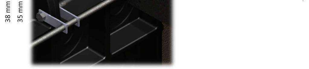
9 Fig Maximum tensile stress EXTENDED BELT ASSESSMENT For load of 40 kn/m 2 (D class) on the suspended lower belt acting as a console with 0.18 m in length the concluded bending moment is 0.64 knm. For load of 16 kn/m 2 (B class) on the lower belt supported on both ends by the concrete ring and acting as a plain beam with 0.46 m in length the concluded bending moment is 1,69 knm. Both values do not exceed the projected value of bearing capacity of 1.74 knm/m. The crosssection is therefore sufficient. 5. ASSEMBLY SCHEDULE The Zekan cable cellars must be laid in well compact ballast bed of well graded gravel (GW) 1/8 fraction of minimum width 200 mm. The backfill must be of the same material (GW, 1/8 fraction) and must be well compacted with layers of maximum width 200 mm. The backfill will be used to the level of the bottom edge of the bearing concrete ring. The bearing ring, the height of which will change depending on the load class, fulfils bearing function for potential concentrated load in the vicinity of the cellar entry and at the same time reinforces the cellar entry. For the load class B and load model 71 its height will be at minimum 200 mm and it will be made of plain concrete. For load classes C and D its height will be 400 mm and it will be equipped with three reinforcing rods attached to the cellar structure via steel joints. In the ring there will be reinforcement along the whole circumference. However, it will be connected to the cellar structure only in points with bolted connections of the individual cellar plates. For load class A no upper bearing ring is necessary. The following concrete ring will be placed on the bottom edge of the first piece (in the depth of 800 mm), it will be 200 mm high and will be equipped with two reinforcing rods. The load class A cable trench cover plate PVC and PE pipes Page 9/15
10 is an exception. For this class the concrete ring will be placed on the bottom edge of the first adjusting belt (in the depth of 1,080 mm). In case the cellar is raised above the base height, some deeper joints will need to be equipped with another ring of reinforced concrete. For load A and B the concrete ring will be placed on the bottom edge of every third adjusting belt; for load classes C and D and load model 71 on the bottom edge of every second adjusting belt. If the lowest ring of reinforced concrete is placed at the bottom edge of the cellar, the lowest concrete ring can be replaced with steel sections. The steel sections will shore the longer walls of the cellar and will be placed equally along its length depending on their number. For load classes A and B, two shores are sufficient. For load class C and D and load model 71 four such shores are required. The steel shores will be strutted against the cellar wall by means of base plates with minimum area of 1 dm 2, so the cellar walls do not get pierced. The shore will be made of L 50 5 section or bigger appropriate section (with minimum area of 500 mm 2 ) with similar strut characteristics. The rings will be made of C20/25 concrete and their width will be at minimum 200 mm from the outer edge of reinforcing ribs. The shore will be ribbed with diameter of 12 mm made of B 500 B steel (in compliance with [7] ) and along the longer cellar wall it will be attached to the structure by means of steel joints. If the pit is placed near the railway where there is a risk of stray current, the shore needs to be welded in the horizontal rings! 6. CONCLUSION A detailed structural analysis by means of the method of finite elements was performed and it was proved that the Zekan XXL cable cellar when installed in compliance with chapter 5 conforms to the conditions appropriate for the loads for coverage of vertical structures of types A15, B 125, C 250 and D 400 in compliance with the applicable standard EN 124 and to the load model 71 in compliance with the applicable standard ČSN EN Please note that in compliance with Decree SŽDC S3 any part of the pit can be placed within the distance of 2.2 m in railway stations and shunts (in narrow space the distance of 2.05 m is permissible, if the length of the base does not exceed 2.0 m) and in the open track up to the outmost switch by the distance of 2.35 m from the railway axis. The assembly procedures proposed are applicable to cellar heights up to 1920 mm. For installation of cellars above this height please consult a structural designer. cable trench cover plate PVC and PE pipes Page 10/15


11 cable trench cover plate PVC and PE pipes Page 11/15


12 cable trench cover plate PVC and PE pipes Page 12/15


13 cable trench cover plate PVC and PE pipes Page 13/15


14 cable trench cover plate PVC and PE pipes Page 14/15


15 cable trench cover plate PVC and PE pipes Page 15/15
Code No: R Set No. 1
 Code No: R059210303 Set No. 1 II B.Tech I Semester Regular Examinations, November 2006 MECHANICS OF SOLIDS ( Common to Mechanical Engineering, Mechatronics, Metallurgy & Material Technology, Production
Special Provision No. 421F01 April 2006
 RIGID PIPE CULVERTS Item No. FLEXIBLE PIPE CULVERTS Item No. CSP ARCH CULVERTS Item No. STRUCTURAL PLATE CSP Item No. CORRUGATED STEEL PIPE EXTENSIONS Item No. ROCK EXCAVATION FOR CULVERTS Item No. CLAY
Level 6 Graduate Diploma in Engineering Structural analysis
 9210-111 Level 6 Graduate Diploma in Engineering Structural analysis Sample Paper You should have the following for this examination one answer book non-programmable calculator pen, pencil, ruler, drawing
Scientific Seminar Design of Steel and Timber Structures SPbU, May 21, 2015
 Riga Technical University Institute of Structural Engineering and Reconstruction Scientific Seminar The research leading to these results has received the funding from Latvia state research programme under
Finite element simulation of railway through concrete-filled steel tube tied arch bridge based on static analysis
 207 th International Civil Engineering, Architecture and Machinery Conference(ICEAMC 207) Finite element simulation of railway through concrete-filled steel tube tied arch bridge based on static analysis
TUNNEL LINER PLATE INTRODUCTION GENERAL APPLICATIONS CHAPTER 11
 CHAPTER 11 INTRODUCTION The open-trench method of placing underground conduits is commonly used on new construction of culverts, sewers and underpasses. Interference with traffic, as well as inconvenience
RETAINING WALL SYSTEM. ViaWall. ViaWall A. ViaWall B. ViaBlock
 RETAINING WALL SYSTEM ViaWall ViaWall A ViaWall B ViaBlock Table of contents Introduction page 1 ViaWall type A Elements of the system 1. Reinforced concrete panel 2. Reinforcing meshes 3. U-bolts Additional
EGCE 406: Bridge Design
 EGCE 406: Bridge Design Design of Slab for Praveen Chompreda Mahidol University First Semester, 2006 Bridge Superstructure Outline Components of bridge Superstructure Types Materials Design of RC Deck
APPENDIX B ABC STRUCTURES DESIGN GUIDE
 APPENDIX B ABC STRUCTURES DESIGN GUIDE The Cohos Evamy Partners TABLE OF CONTENTS Page No. DISCLAIMER... I 1. STRUCTURAL DESIGN GUIDELINES... 1 2. GENERAL REQUIREMENTS (FIGURE B.2, STEP 1)... 1 3. GENERAL
Verification of Welded eaves moment connection of open sections
 Verification of Welded eaves moment connection of open sections Ing. Lukáš Gödrich June 2014 1 Description The objective of this study: verification of CBFEM IDEARS software with component method. Description
Sabah Shawkat Cabinet of Structural Engineering 2017
 3.9 Concrete Foundations A foundation is a integral part of the structure which transfer the load of the superstructure to the soil without excessive settlement. A foundation is that member which provides
Question Paper Code : 11410
 Reg. No. : Question Paper Code : 11410 B.E./B.Tech. DEGREE EXAMINATION, APRIL/MAY 2011 Fourth Semester Mechanical Engineering ME 2254 STRENGTH OF MATERIALS (Common to Automobile Engineering and Production
16. Design of Pipeline Structures.
 16. Design of Pipeline Structures. a. General. 1) The following guidelines are for the design of structures for water and sewer pipelines including structural concrete and miscellaneous metals design.
ASSIGNMENT 1 ANALYSIS OF PRESTRESS AND BENDING STRESS BFS 40303
 Instruction : Answer all question ASSIGNMENT 1 ANALYSIS OF PRESTRESS AND BENDING STRESS BFS 40303 1. A rectangular concrete beam, 100 mm wide by 250 mm deep, spanning over 8 m is prestressed by a straight
SuperCor A NEW GENERATION OF BRIDGES
 SuperCor A NEW GENERATION OF BRIDGES SuperCor versatile structures are used for roads and railways and industrial applications as well as for reinforcement and reconstruction of existing structures such
CONSTRUCTION SPECIFICATION FOR THE INSTALLATION OF ELECTRICAL CHAMBER
 ONTARIO PROVINCIAL STANDARD SPECIFICATION METRIC OPSS 602 MARCH 1993 CONSTRUCTION SPECIFICATION FOR THE INSTALLATION OF ELECTRICAL CHAMBER 602.01 SCOPE 602.02 REFERENCES 602.05 MATERIALS TABLE OF CONTENTS
3.5 What guidance is there?
 3.5 What guidance is there? 3.5.1 General A number of specifications and codes of practice for the use of road plates were identified during the literature review. The main points from these documents
UNIT-1 RETAINING WALLS
 UNIT-1 RETAINING WALLS PART-A 1. Describe about Retaining wall. 2. Define gravity retaining walls. BT-1 3. Classify the types of retaining walls. 4. Explain cantilever retaining wall? 5. Describe about
Design of Gravity Flow Pipes 121 = UNIT WT OF SOIL. P d = H H. D = 2r. P x LIVE LOAD PIPE WALLS ARE CLADDING FOR THE SOIL COLUMN SOIL SECTION AA
 Design of Gravity Flow Pipes 11 deflection. Some pipes manufactured in this manner are sometimes referred to as semirigid. This is simply a misnomer. Many solid wall PVC and ductile iron pipes are actually
Council on Tall Buildings
 Structure Design of Sino Steel (Tianjin) International Plaza Xueyi Fu, Group Chief Engineer, China Construction Design International 1 1 Brief of Project 2 Location: Tianjin Xiangluowan Business District
VOLUNTARY - EARTHQUAKE HAZARD REDUCTION IN EXISTING HILLSIDE BUILDINGS (Division 94 Added by Ord. No. 171,258, Eff. 8/30/96.)
") DIVISION 94 VOLUNTARY - EARTHQUAKE HAZARD REDUCTION IN EXISTING HILLSIDE BUILDINGS (Division 94 Added by Ord. No. 171,258, Eff. 8/30/96.) SEC. 91.9401. PURPOSE. (Amended by Ord. No. 172,592, Eff. 6/28/99,
DIVISION 94 VOLUNTARY - EARTHQUAKE HAZARD REDUCTION IN EXISTING HILLSIDE BUILDINGS (Division 94 Added by Ord. No. 171,258, Eff. 8/30/96.) SEC. 91.9401. PURPOSE. (Amended by Ord. No. 172,592, Eff. 6/28/99,
Austral Deck Design for Construction Loading. Permanent formwork and Span capability
 Austral Deck Design for Construction Loading Permanent formwork and Span capability Introduction The purpose of this document is to demonstrate the process of designing Austral Deck as formwork complying
1 Prepared By:Mr.A.Sathiyamoorthy, M.E., AP/Civil
 UNIVERSITY QUESTIONS PART A UNIT 1: INTRODUCTION THEORY AND BEHAVIOUR 1. List the loss of prestress. 2. Define axial prestressing. 3. What is the need for the use of high strength concrete and tensile
Structural behaviour and failure mechanisms of concrete monoblock railway sleepers
 Structural behaviour and failure mechanisms of concrete monoblock railway sleepers Olli Kerokoski, Antti Nurmikolu and Tommi Rantala Department of Civil Engineering, Tampere University of Technology, P.O.
Analysis of Buried Arch Structures; Performance Versus Prediction
 Analysis of Buried Arch Structures; Performance Versus Prediction D.A. Jenkins: Reinforced Earth Pty Ltd, Somersby, NSW, Australia Synopsis: The Reinforced Earth Group introduced the TechSpan arch system
Structural Calculations for standard BALCONY 1 system handrail using 55mm diameter posts (48.3mm x 5mm CHS) & 150 x 150 x 15mm base plates
 & 150 x 150 x 15mm base plates") Balcony 1 system handrail PAGE 1 (B1NB55150150BP061016) Structural Calculations for standard BALCONY 1 system handrail using 55mm diameter posts (48.3mm x 5mm CHS) & 150 x 150 x 15mm base plates Our ref:
Balcony 1 system handrail PAGE 1 (B1NB55150150BP061016) Structural Calculations for standard BALCONY 1 system handrail using 55mm diameter posts (48.3mm x 5mm CHS) & 150 x 150 x 15mm base plates Our ref:
Class Topics & Objectives
 EGCE 406: Bridge Design Design of Slab for Bridge Deck Praveen Chompreda, Ph.D. Mahidol University First Semester, 2010 Class Topics & Objectives Topics Objective Bridge Superstructures Students can identify
Design Methods of Elements from Cross-Laminated Timber Subjected to Flexure
 RIGA TECHNICAL UNIVERSITY INSTITUTE OF STRUCTURAL ENGINEERING AND RECONSTRUCTION A.Vilguts, D.Serdjuks, L.Pakrastins Design Methods of Elements from Cross-Laminated Timber Subjected to Flexure RIGA 2015
Precast Concrete Trench Drain Systems INSTALLATION INSTRUCTIONS
 Precast Concrete Trench Drain Systems INSTALLATION INSTRUCTIONS GENERAL INSTALLATION INSTRUCTIONS 1 Ensure that the trench where the channels are going to be installed has enough room for the appropriate
EXPERIMENTAL PROGRAMME
 CHAPTER 3 EXPERIMENTAL PROGRAMME 3.1 INTRODUCTION The critical review of the literature presented in the previous chapter reveals the limitations of the experimental studies carried out so far in the field
Design of Steel-Concrete Composite Bridges
 Design of Steel-Concrete Composite Bridges to Eurocodes Ioannis Vayas and Aristidis Iliopoulos CRC Press Taylor & Francis Croup Boca Raton London New York CRC Press is an imprint of the Taylor & Francis
COMMONWEALTH OF PENNSYLVANIA DEPARTMENT OF TRANSPORTATION BUREAU OF DESIGN
 INSTRUCTIONS: FOR USAGE OF OR PIPE, REFER TO D.M., TABLE 10.3.5 FOR DIAMETERS GREATER THAN mm (4), USE DESIGN FILL HEIGHT TABLES. LOCAL AUTHORITIES MAY USE OR DESIGN FILL HEIGHT TABLES. SPECIFY SHORING/TRENCH
(SIZE) MANHOLES CATCH BASINS AND DITCH INLETS -Item No. ADJUSTING AND REBUILDING MANHOLES, CATCH BASINS AND DITCH INLETS - Item No.
 MANHOLES CATCH BASINS AND DITCH INLETS -Item No. ADJUSTING AND REBUILDING MANHOLES, CATCH BASINS AND DITCH INLETS - Item No.") (SIZE) MANHOLES CATCH BASINS AND DITCH INLETS -Item No. ADJUSTING AND REBUILDING MANHOLES, CATCH BASINS AND DITCH INLETS - Item No. Special Provision No. 407S06 July 2010 Aggregate Requirements, Lift Rings,
(SIZE) MANHOLES CATCH BASINS AND DITCH INLETS -Item No. ADJUSTING AND REBUILDING MANHOLES, CATCH BASINS AND DITCH INLETS - Item No. Special Provision No. 407S06 July 2010 Aggregate Requirements, Lift Rings,
ST7008 PRESTRESSED CONCRETE
 ST7008 PRESTRESSED CONCRETE QUESTION BANK UNIT-I PRINCIPLES OF PRESTRESSING PART-A 1. Define modular ratio. 2. What is meant by creep coefficient? 3. Is the deflection control essential? Discuss. 4. Give
Response Analysis of an RC Cooling Tower Under Seismic and Windstorm Effects D. Makovička
 Response Analysis of an RC Cooling Tower Under Seismic and Windstorm Effects D. Makovička The paper compares the RC structure of a cooling tower unit under seismic loads and under strong wind loads. The
Reconstruction of Space Steel Constructions
 28 September 2 October 2009, Universidad Politecnica de Valencia, Spain Alberto DOMINGO and Carlos LAZARO (eds.) Reconstruction of Space Steel Constructions Jan BRODNIANSKY*, Zoltán AGÓCS, Rudolf ÁROCH,
The Most Advanced Name in Water Management Solutions TM. The most cost-effective slotted and trench surface drain systems.
 The Most Advanced Name in Water Management Solutions TM The most cost-effective slotted and trench surface drain systems. A sensible alternative to metal and concrete Since 1987, Duraslot surface drains
EN REINFORCED MASONRY DESIGN EXAMPLE 1 (NOTE: THIS USES THE UK NATIONAL ANNEX NDP VALUES)
") 42.50 10.00 3.00 20.00 EN 1996-1-1 REINFORCED MASONRY DESIGN EXAMPLE 1 (NOTE: THIS USES THE UK NATIONAL ANNEX NDP VALUES) Reinforced Masonry - Reinforced Brickwork Stem Cantilever Pocket-Type Retaining
42.50 10.00 3.00 20.00 EN 1996-1-1 REINFORCED MASONRY DESIGN EXAMPLE 1 (NOTE: THIS USES THE UK NATIONAL ANNEX NDP VALUES) Reinforced Masonry - Reinforced Brickwork Stem Cantilever Pocket-Type Retaining
Water Channeling System
 Water Channeling System BUILDING S FLOORING ROOFING PASSIVE FIRE PROTECTION www.laydex.ie Allied Industrial Estate Kylemore Rd Dublin 10 sales@laydex.ie MufleSystem Benefits EASY TO CONNECT STACKABLE EASY
ULTIMATE LOAD-CARRYING CAPACITY OF SELF-ANCHORED CONCRETE SUSPENSION BRIDGE
 ULTIMATE LOAD-CARRYING CAPACITY OF SELF-ANCHORED CONCRETE SUSPENSION BRIDGE Meng Jiang*, University of Technology Dalian, P. R. China Wenliang Qiu, University of Technology Dalian, P. R. China Lihua Han,
COLUMNS 1- Definition: The Egyptian code defines columns as : 2- Types of concrete columns
 COLUMNS 1- Definition: Columns are vertical compression members which carry primarily axial compression load; the axial load may be associated with bending moments in one or two directions, as shown in
STRUCTURAL CALCULATIONS
 STRUCTURAL CALCULATIONS FOR BALUSTRADES USING BALCONY 2 SYSTEM HANDRAIL WITHOUT INTERNAL REINFORCING BAR AND WITH 60 x 24mm STEEL POSTS BY BALCONY SYSTEMS LIMITED Balcony 2 System, posts in Royal Chrome
TEST AND ANALYSIS OF A SHORT-SPAN RAILWAY BRIDGE
 Proceedings of the 6th International Conference on Mechanics and Materials in Design, Editors: J.F. Silva Gomes & S.A. Meguid, P.Delgada/Azores, 26-30 July 2015 PAPER REF: 5756 TEST AND ANALYSIS OF A SHORT-SPAN
Technical Documentation
 Technical Documentation Underground Container F-Line 1.500L, 3.000L, 5.000L, 7.500L, 10.000L 1. Location 1.1. Position to buildings The excavation space must not be within the minimum distance to buildings,
Long-term Stress of Simply Supported Steel-concrete Composite Beams
 The Open Construction and Building Technology Journal, 2011, 5, 1-7 1 Open Access Long-term Stress of Simply Supported Steel-concrete Composite Beams Min Ding 1,2, Xiugen Jiang 1, Zichen Lin 3 and Jinsan
Special Provision No. 421S01 November 2006
 RIGID PIPE CULVERTS (75 Year DSL) Item No. RIGID PIPE CULVERTS (50 Year DSL) Item No. RIGID PIPE CULVERTS (25 Year DSL) Item No. FLEXIBLE PIPE CULVERTS (75 Year DSL) Item No. FLEXIBLE PIPE CULVERTS (50
GUSSET PLATES IN RAILROAD TRUSS BRIDGES FINITE ELEMENT ANALYSIS AND COMPARISON WITH WHITMORE TESTING
 GUSSET PLATES IN RAILROAD TRUSS BRIDGES FINITE ELEMENT ANALYSIS AND COMPARISON WITH WHITMORE TESTING Walid S. Najjar, Ph.D., P.E. 1, Frank DeOrtentiis, P.E. WSP SELLS 555 Pleasantville Road, Briarcliff
OXFORD ENGINEERING COLLEGE (NAAC Accredited with B Grade) Department of Civil Engineering LIST OF QUESTIONS
 Department of Civil Engineering LIST OF QUESTIONS") OXFORD ENGINEERING COLLEGE (NAAC Accredited with B Grade) Department of Civil Engineering LIST OF QUESTIONS Year/ Sem. : IV / VII Staff Name : S.LUMINA JUDITH Subject Code : CE 6702 Sub. Name : PRE STRESSED
OXFORD ENGINEERING COLLEGE (NAAC Accredited with B Grade) Department of Civil Engineering LIST OF QUESTIONS Year/ Sem. : IV / VII Staff Name : S.LUMINA JUDITH Subject Code : CE 6702 Sub. Name : PRE STRESSED
NATIONAL CORRUGATED STEEL PIPE ASSOCIATION
 NATIONAL CORRUGATED STEEL PIPE ASSOCIATION Designdatasheet No. 18 ISSUED: June 1995 UPDATED: September 1999 This Data Sheet is for general use only and should not be used without first securing competent
Comparison of One-way and Two-way slab behavior. One-way slabs carry load in one direction. Two-way slabs carry load in two directions.
 Two-way Slabs Comparison of One-way and Two-way slab behavior One-way slabs carry load in one direction. Two-way slabs carry load in two directions. Comparison of One-way and Two-way slab behavior One-way
UNIVERSITY OF BOLTON WESTERN INTERNATIONAL COLLEGE FZE. BEng (HONS) CIVIL ENGINEERING SEMESTER ONE EXAMINATION 2018/2019
 CIVIL ENGINEERING SEMESTER ONE EXAMINATION 2018/2019") OCD030 UNIVERSITY OF BOLTON WESTERN INTERNATIONAL COLLEGE FZE BEng (HONS) CIVIL ENGINEERING SEMESTER ONE EXAMINATION 2018/2019 ADVANCED STRUCTURAL ANALYSIS AND DESIGN MODULE NO: CIE6001 Date: Tuesday 8
OCD030 UNIVERSITY OF BOLTON WESTERN INTERNATIONAL COLLEGE FZE BEng (HONS) CIVIL ENGINEERING SEMESTER ONE EXAMINATION 2018/2019 ADVANCED STRUCTURAL ANALYSIS AND DESIGN MODULE NO: CIE6001 Date: Tuesday 8
STRUCTURAL CALCULATIONS
 STRUCTURAL CALCULATIONS FOR BALUSTRADES USING BALCONY 1 SYSTEM HANDRAIL WITHOUT INTERNAL REINFORCING BAR. POSTS ARE 48.3mm DIAMETER AT 1.9m MAXIMUM CENTRES BY BALCONY SYSTEMS LIMITED Balcony 1 System,
STEEL DESIGNERS MANUAL
 STEEL DESIGNERS MANUAL SIXTH EDITION The Steel Construction Institute Edited by Buick Davison Department of Civil & Structural Engineering, The University of Sheffield Graham W. Owens Director, The Steel
Introduction to Structural Analysis TYPES OF STRUCTURES LOADS AND
 AND Introduction to Structural Analysis TYPES OF STRUCTURES LOADS INTRODUCTION What is the role of structural analysis in structural engineering projects? Structural engineering is the science and art
A Guide for the Interpretation of Structural Design Options for Residential Concrete Structures
 CFA Technical Note: 008-2010 A Guide for the Interpretation of Structural Design Options for Residential Concrete Structures CFA Technical This CFA Technical Note is intended to serve as a guide to assist
CHAPTER 3 BEHAVIOUR OF FERROCEMENT HOLLOW SLABS
 30 CHAPTER 3 BEHAVIOUR OF FERROCEMENT HOLLOW SLABS 3.1 INTRODUCTION There are numerous similarities between ferrocement and reinforced concrete. Both use similar matrix and reinforcement materials. They
Design of large scale wind turbine towers in seismic areas
 Design of large scale wind turbine towers in seismic areas C.C. Baniotopoulos, I. Lavassas, G. Nikolaidis, P.Zervas Institute of Metal Structures, Dept. of Civil Engineering, A.U.Th., Thessaloniki, Greece
CE2401-DESIGN OF REINFORCED CONCRETE AND BRICK MASONRY QUESTION BANK
 CE2401-DESIGN OF REINFORCED CONCRETE AND BRICK MASONRY QUESTION BANK UNIT-1 PART-A 1. What is a Retaining wall? 2. What are the disadvantages of gravity retaining walls? 3. What are the types of retaining
STRUCTURAL CALCULATIONS
 STRUCTURAL CALCULATIONS FOR BALUSTRADES USING BALCONY 1 SYSTEM HANDRAIL WITH INTERNAL 58 x 4mm STEEL REINFORCING BAR AND WITH 48.3mm DIAMETER X 5mm STEEL STANDARDS BY BALCONY SYSTEMS LIMITED Balcony 1
Plastic pipes in construction
 Plastic pipes in construction Choose the material that best suits your needs. Historical Canplast marketed PVC pipes in 1964, PE pipes in 1980 and PP pipes in 2005. Properties of plastics Raw materials
Laboratory Accreditation Programmes
 Laboratory Address PO Box 6178, Upper Riccarton, Christchurch, 8442 52 Hayton Road, Sockburn, Christchurch, 8042 Telephone 03 343-3530 URL Authorised Representative Client No. 153 Programme Accreditation
Preliminary design of concrete structures 124SDP1
 124SDP1 1 Content 1 Content...- 1-2 Preliminary design...- 2-2.1 Reinforced concrete slab...- 2-2.2 Reinforced concrete beam...- 3-2.3 Reinforced concrete column...- 4 - Department of Concrete and Masonry
Post-tensioned prestressed concrete bridge - assignment
 Post-tensioned prestressed concrete bridge - assignment Design a post-tensioned prestressed concrete bridge of a three-span arrangement. The construction is prestressed at the age of 7 days and put into
 VALLIAMMAI ENGINEERING COLLEGE DEPARTMENT OF MECHANICAL ENGINEERING QUESTION BANK CE 6306 - STRENGTH OF MATERIALS UNIT I STRESS STRAIN DEFORMATION OF SOLIDS PART- A (2 Marks) 1. What is Hooke s Law? 2.
Influence of arch bridge skewness
 EUROSTEEL 2017, September 13 15, 2017, Copenhagen, Denmark ABSTRACT Influence of arch bridge skewness Hans De Backer*,a, Amelie Outtier a, Evy Van Puymbroeck*,a, Philippe Van Bogaert a a Ghent University,
Structural Characteristics of New Composite Girder Bridge Using Rolled Steel H-Section
 Proc. Schl. Eng. Tokai Tokai Univ., Univ., Ser. ESer. E 41 (2016) (2016) - 31-37 Structural Characteristics of New Composite Girder Bridge Using Rolled Steel H-Section by Mohammad Hamid ELMY *1 and Shunichi
(laboratory) (fall semester)
 (fall semester)") Civil Engineering Courses-1 CIV 211/Surveying Prerequisite: MAT 127 An introduction to the theory and applications of modern surveying processes. Students use optical and digital land surveying instruments
Civil Engineering Courses-1 CIV 211/Surveying Prerequisite: MAT 127 An introduction to the theory and applications of modern surveying processes. Students use optical and digital land surveying instruments
PRESTRESSED CONCRETE STRUCTURES. Amlan K. Sengupta, PhD PE Department of Civil Engineering Indian Institute of Technology Madras
 PRESTRESSED CONCRETE STRUCTURES Amlan K. Sengupta, PhD PE Department of Civil Engineering Indian Institute of Technology Madras Module - 4: Design of Members Lecture - 17: Design of Members for Axial Tension
SECTION A-A NTS. Figure 4.1 Alternative Flow Dispersal Trench NOTES:
 Figure 4.1 Alternative Flow Dispersal Trench NOTES: galvanized bolts 2" x 12" pressure treated grade board 2" x 2" notches 18" O.C. *20% max 12" min. 36" max 1' - 6" min *20% max 4" x 4" support post clean
BEHAVIOR OF INFILL MASONRY WALLS STRENGTHENED WITH FRP MATERIALS
 BEHAVIOR OF INFILL MASONRY WALLS STRENGTHENED WITH FRP MATERIALS D.S. Lunn 1,2, V. Hariharan 1, G. Lucier 1, S.H. Rizkalla 1, and Z. Smith 3 1 North Carolina State University, Constructed Facilities Laboratory,
 1.1. A solid circular post ABC (see figure) supports a load P 1 = 11.000 N acting at the top. A second load P 2 is uniformly distributed around the shelf at B. The diameters of the upper and lower parts
Footings GENERAL CONSIDERATIONS 15.2 LOADS AND REACTIONS 15.4 MOMENT IN FOOTINGS
 4 Footings GENERAL CONSIDERATIONS Provisions of Chapter 15 apply primarily for design of footings supporting a single column (isolated footings) and do not provide specific design provisions for footings
Rail Track Analysis Wizard
 Rail Track Analysis Wizard M I D A S I T 111-1 01 Rail Track Analysis Wizard The Rail Track Analysis Wizard builds a model that is used for checking the additional stresses and the displacements due to
Schöck Isokorb type CV
 Schöck Isokorb type The Schöck Isokorb type is suitable for supported reinforced concrete slabs. (C concrete slab) It transmits positive shear force (vertical shear). 71 72 Section/element arrangement
UNIVERSITY OF BOLTON WESTERN INTERNATIONAL CENTRE FZE. BEng (HONS) CIVIL ENGINEERING SEMESTER ONE EXAMINATION 2015/2016
 CIVIL ENGINEERING SEMESTER ONE EXAMINATION 2015/2016") OCD59 UNIVERSITY OF BOLTON WESTERN INTERNATIONAL CENTRE FZE BEng (HONS) CIVIL ENGINEERING SEMESTER ONE EXAMINATION 2015/2016 ADVANCED STRUCTURAL ANALYSIS AND DESIGN MODULE NO: CIE6001 Date: Tuesday 12
OCD59 UNIVERSITY OF BOLTON WESTERN INTERNATIONAL CENTRE FZE BEng (HONS) CIVIL ENGINEERING SEMESTER ONE EXAMINATION 2015/2016 ADVANCED STRUCTURAL ANALYSIS AND DESIGN MODULE NO: CIE6001 Date: Tuesday 12
CHAPTER 11: PRESTRESSED CONCRETE
 CHAPTER 11: PRESTRESSED CONCRETE 11.1 GENERAL (1) This chapter gives general guidelines required for the design of prestressed concrete structures or members with CFRM tendons or CFRM tendons in conjunction
7th task: Pad footing
 7th task: Pad footing Pad footing Design of dimensions Design of plain concrete pad footing Design of reinforced concrete pad footing Drawings (shape and reinforcement of footings) Difference between PC/RC
BEAMS: COMPOSITE BEAMS; STRESS CONCENTRATIONS
 BEAMS: COMPOSITE BEAMS; STRESS CONCENTRATIONS Slide No. 1 Bending of In the previous discussion, we have considered only those beams that are fabricated from a single material such as steel. However, in
TABLE OF CONTENTS
 DIVISION 33: SEWER AND SEPTIC SYSTEMS 33 3633 UTILITY SEPTIC TANK DRAINAGE FIELD TABLE OF CONTENTS 33 0000-1 SECTION 33 3633-- UTILITY SEPTIC TANK DRAINAGE FIELD PART 1 - GENERAL 1.1 SUMMARY A. Includes
CLT Structural Design Sylvain Gagnon, Eng. February 8, 2011 Vancouver
 www.fpinnovations.ca CLT Structural Design Sylvain Gagnon, Eng. February 8, 2011 Vancouver Structural Design Handbook 10/02/2011 2 Critical Characteristics for CLT used as floor/roof Short-term and long-term
UNIT V PART A
 1. Why concrete bridges are used? [N/D 14] UNIT V PART A a. Reinforced concrete and prestressed concrete have been found most suited for the construction of high way bridges the former for small and medium
SOIL PRESSURE IN EMBANKMENT STABILIZATIONS
 SOIL PRESSURE IN EMBANKMENT STABILIZATIONS Analysis of the 3D shadowing effect of piles Dipl.-Ing. M. Filus Fides DV-Partner GmbH ABSTRACT: Pile checks required by the codes alone are usually not sufficient
Eurocode 8 Timber and Masonry structures
 Brussels, 18-20 February 2008 Dissemination of information workshop 1 Eurocode 8 Timber and Masonry structures E C Carvalho, Chairman TC250/SC8 Brussels, 18-20 February 2008 Dissemination of information
Section 401. PIPE CULVERTS
 401.02 Section 401. PIPE CULVERTS 401.01. Description. This work consists of constructing pipe culverts of the size and class required, including excavation and backfill. 401.02. Materials. Provide materials
Gambit Centrum Oprogramowania i Szkoleń Sp. z o.o. Mathcad 14 Roark's Formulas for Stress and Strain
 Mathcad 14 Roark's Formulas for Stress and Strain Table of Contents About Mathcad E-Books Notes on the Organization and Special Features of Roark's Formulas for Stress and Strain Preface by Warren C. Young
NATIONAL CERTIFICATE (VOCATIONAL) NQF LEVEL
 NQF LEVEL") MARKING GUIDELINES NATIONAL CERTIFICATE (VOCATIONAL) NQF LEVEL 3 NOVEMBER 2009 S This marking guideline consists of 7 pages. (MARKING GUIDELINES) -2- NC420(E)(N27)V QUESTION 1 APPLICATION OF SABS/SANS
MARKING GUIDELINES NATIONAL CERTIFICATE (VOCATIONAL) NQF LEVEL 3 NOVEMBER 2009 S This marking guideline consists of 7 pages. (MARKING GUIDELINES) -2- NC420(E)(N27)V QUESTION 1 APPLICATION OF SABS/SANS
SRPE AASHTO Specifications.
 SRPE AASHTO Specifications July 19, 2013 Steel Ribbed HDPE = SRHDPE = SRPE Now has AASHTO Design and Construction Specifications for SRPE. 2 But wait there is more AASHTO Bridge Design Specs - Section
Draft. Not Yet Approved SECTION 10.1 GENERAL SCOPE DEFINITIONS
 SECTION 10.1 GENERAL 10.1.1 SCOPE This part of the Manual covers the structural design and installation of reinforced concrete pipe for railway culverts. Pipe geometry may be circular, arch, or elliptical.
FLAT. The system: it supports 3 load classes (A15, B125, C250) in compliance with Standard EN 1433
 in compliance with Standard EN 1433") The system: it supports 3 load classes (A15, B125, C250) in compliance with Standard EN 1433 it is made up of a channel - entirely made from HD-PE - which needs no strengthening frame it has a wide usable
The system: it supports 3 load classes (A15, B125, C250) in compliance with Standard EN 1433 it is made up of a channel - entirely made from HD-PE - which needs no strengthening frame it has a wide usable
Stability of a Mechanically Stabilized Earth Wall
 Stability of a Mechanically Stabilized Earth Wall GEO-SLOPE International Ltd. www.geo-slope.com 1400, 633-6th Ave SW, Calgary, AB, Canada T2P 2Y5 Main: +1 403 269 2002 Fax: +1 403 266 4851 Introduction
Fire Safety Day Fire Behaviour of Steel and Composite Floor Systems Simple design method
 Fire Safety Day 011 Fire Behaviour of Steel and Composite Floor Systems method Prof. Colin Bailey 1 3 Content of presentation in a fire situation method of reinforced concrete slabs at 0 C Floor slab model
Improving Thermal Insulation Properties for Prefabricated Wall Components Made Of Lightweight Aggregate Concrete with Open Structure
 IOP Conference Series: Materials Science and Engineering PAPER OPEN ACCESS Improving Thermal Insulation Properties for Prefabricated Wall Components Made Of Lightweight Aggregate Concrete with Open Structure
ARMOR-BLOCK. Installation guide. Installation Manual: ARMOR-BLOCK Retaining Wall System. Cap Block. Exposed void for planting.
 ARMOR-BLOCK Installation guide Cap Block Exposed void for planting In situ soil Engineered backfill Compacted and prepared base Setback Lip Ph 0800 655 00 or visit www.csppacific.co.nz 19 February 08 /
SHEAR DEFORMATION IMPACT ON DEFLECTION OF COMPOSITE BRIDGE GIRDERS 1 INTRODUCTION
 SHEAR DEFORMATION IMPACT ON DEFLECTION OF COMPOSITE BRIDGE GIRDERS J Bujňák University of Žilina, Slovakia J Odrobiňák University of Žilina, Slovakia Abstract The aim of the article is to present a study
ATENA Program Documentation Part 4-8
 Červenka Consulting s.r.o. Na Hrebenkach 55 150 00 Prague Czech Republic Phone: +420 220 610 018 E-mail: cervenka@cervenka.cz Web: http://www.cervenka.cz ATENA Program Documentation Part 4-8 ATENA Science
9.6 Circular Prestressing
 9.6 Circular Prestressing This section covers the following topics. Introduction General Analysis and Design Prestressed Concrete Pipes Liquid Storage Tanks Ring Beams Conclusion 9.6.1 Introduction When
Chapter. Masonry Design
 Chapter Masonry Design The masonry design section contains modules for the analysis of reinforced masonry beams subjected to pure bending and unreinforced masonry walls subjected to axial compression and
NEMO TANK INSTALLATION GUIDE INSTALLATION INSTRUCTIONS FOR THE NEMO TANK STAGE
 NEMO TANK INSTALLATION GUIDE INSTALLATION INSTRUCTIONS FOR THE NEMO TANK STAGE 1. Before undertaking the work 2. Receiving the materials 3. Handling and storage 4. Tank layout 5. Installing the tanks STAGE
PRECAST FIBRE REINFORCED CONCRETE ELEMENT OF RETAINING WALL
 PRECAST FIBRE REINFORCED CONCRETE ELEMENT OF RETAINING WALL NOVÁK Josef 1, BREJCHA Vladimír 2, BROUKALOVÁ Iva 3, KOHOUTKOVÁ Alena 4, FLÁDR Josef 5 Abstract Fibre reinforced concrete (FRC) is a material