GROUNDING MATERIAL PROTECTION BY GROUNDING 3.2
|
|
|
- Alannah Beasley
- 5 years ago
- Views:
Transcription
61 466 33 33, Fax ++41 (0)61 461")
 997 8855,")
1 GROUNDING MATERIAL PROTECTION BY GROUNDING Woertz AG Hofackerstrasse 47, P.O. Box 948, CH-4132 Muttenz 1, Switzerland Phone ++41 (0) , Fax ++41 (0) Woertz USA 151 Discovery Drive, Unit 111 Colmar, PA Phone (215) , Fax (800)
2 Contents Contents Grounding methods Introduction Grounding in house installations Using metallic water conduits for grounding Foundation grounding Using the reinforcement steels in the concrete foundations Using specially laid conductors in concrete foundations Bonding of structural and dilation joints Connection points Civil protection Civil protection: examples Grounding strips Grounding for lightning protection installations Potential compensation Potential compensation combined with foundation grounding electrodes Relevant norms and principles Materials Universal clamping plate Examples of use of the universal clamping plate Art.No Materials for grounding at metallic water conduits Materials for foundation grounding electrode: reinforcing steel Foundation grounding electrode: use of specially laid conductors for grounding Grounding strips Connecting parts for foundation and grounding strips Materials for potential compensation Materials for grounding busbars Connectors for potential compensation in laboratories, in medically used rooms, against static charges


3 Grounding methods Metallic water conduit Grounding strip Explanations: see page Materials: see page Secure connections with a single product: the universal clamping plate Explanations: see page Materials: see page Reinforcing steel in concrete foundations Specially laid conductors in concrete foundations Explanations: see page Explanations: see page Materials: see page Explanations: see page Materials: see page

4 Introduction Why is grounding used? In electrical installations, grounding is a protective measure. The aim of grounding devices and parts of installations is to prevent that, in case of malfunction, conductive parts that are not designed to carry electricity become live and thereby endanger human beings, animals and objects. With grounding, installations should be switched off in case of malfunction or touch voltages (1) or pace voltages (2) should drop to safe levels. With potential compensation, the aim of grounding is that all parts that are taken into account have the same potential, independently from their location. Therefore, dangerous voltage differences between different parts of an installation or with parts that are directly connected to the earth cannot occur. The aim of grounding in lightning protection installations is that the dangerous voltages and currents occurring with lightnings and atmospheric discharges, are discharged following the shortest and safest way instead of going through other metallic building parts that would be damaged by them. Why foundation grounding? The extensive pipe networks with continuous water conduits of metal with good conductivity used to be available as excellent grounding conductors. Now, the metal conduits are increasingly replaced by non-conductive conduits of plastic or similar materials, which cannot be used for grounding. As an alternative, foundation grounding electrodes and separately laid metal strips in the earth will be used for grounding more often. Note (1) Touch voltage is the part of the grounding voltage that can be bridged by a human being by contact with two body parts. (2) Pace voltage is the part of the grounding voltage that can be bridged by a human with a 1m step
 of the connecting cable is grounded at the transition between the mains and the house installation.")


5 Grounding in house installations The technical norm of Electrosuisse for low voltage installations (NIN) rules, among other things, that grounding with neutral lines of TN systems may only be used if the PEN conductor (1) of the connecting cable is grounded at the transition between the mains and the house installation. In addition, in every building, the grounding electrode, the PEN conductor (1) of the connecting cable, the main grounding conductor, the metallic conduit system, the extensive metal parts of the building structure, and - if it exists - the lightning protection installation have to be connected to each other via a main potential compensator. a b c d For house installations the following grounding elements are recommended: Art. No a) metallic water conduits b) grounding strip Art. No Art. No Art. No c+d) foundation grounding electrode Copper tape Art. No. 4530/... Span-clamp Art. No Art. No universal clamping plate Art. No Who decides about which kind of grounding to use? The electric power company that supplies energy to house installations decides which kind of grounding has to be used in its service area. The following explanations provide information about the construction, the dimensions and the choice of material for the different kinds of grounding that have to be used in certain areas. Note (1) A PEN conductor is a neutral or polar conductor that is grounded and at the same time protects against touch voltage and pace voltage
, are necessary for ensuring a durable good connection to the water conduit.")

6 1. Using metallic water conduits for grounding The connection of the grounding neutral line to the water conduit has to be located directly at the entry of the water conduit into the building. Suitable grounding clamps, which may have to be protected against chemical effects (corrosion), are necessary for ensuring a durable good connection to the water conduit. contact plate span-clamp For the connection with the water conduit, the materials presented on page are very well suited. Using the established and time-tested grounding tapes and the span devices, a suitable grounding clamp can be constructed for all dimensions of conduits. perforated copper tape clamp perforated copper tape 16x2mm Art. No. 4530/... span-clamp Art. No clamp Art. No contact plate for retensioning Art. No copper tapes 40 x 1.5 mm Art. No. 4548/ x 3 mm Art. No. 4556/... span device Art. No /1 for Cu tapes 40 x 1.5 mm and 40 x 3 mm cross-section of conduit at least 120 mm Grounding tapes and span devices: see page Grounding neutral line The right dimensions of the earth connecting tapes and the connecting terminal for the grounding neutral lines depend on the cross-section of the conductor, for which NIN (Electrosuisse norm for low voltage installations) rules: The conductance of the grounding neutral line has to be half of the conductance of a polar conductor of the connecting line and may not be lower than the one of a copper conductor of 16 mm

7 2. Foundation grounding For the construction of foundation grounding electrodes, the principles of publication 4113 by Electrosuisse have to be taken into account. According to them, foundation grounding electrodes have to be at least 70 cm deep in the earth. The minimum cross-section of foundation grounding electrodes is 75 mm 2, and they have to be placed in the foundations of the perimeter walls, so that they enclose the whole building like a closed ring. There are two kinds of foundation grounding electrodes: Example of the use of reinforcement steels in concrete foundations Art. No use of the reinforcement steel in the concrete foundation - use of a specially laid conductor in the concrete foundation Art. No Art. No Art. No Art. No Minimum cross-section of grounding electrodes: 75 mm 2 (steel) 3.2.9
8 2.1 Using the reinforcement steels in the concrete foundations The reinforcement steels in foundations can be used for grounding if their diameter is at least 8 mm. In order to reach the required cross-section of 75 mm 2, at least two steels with a minimum diameter of 8 mm have to be connected to form a ring around the building when reinforcement steels are used for grounding. If the reinforcement steels in the foundations have a diameter of 10 mm or more, one steel forming a ring with good electric conductivity around the building is enough. For the necessary connections, the universal clamping plate Art. No is perfectly suitable because it can be adapted to all positions and its good clamping behaviour guarantees an excellent conductivity of the connections. According to the Electrosuisse principles for foundation grounding electrodes, such connections may never be established with binding wire connecting tag Art. No within the building connecting tag Art. No outside the building connection set Art. No within the building connection set Art. No outside the building connection of two reinforcement steels using the universal clamping plate Art. No The reinforcement steels that are used for grounding always have to be those that are located at the exterior of the building, so that the transition resistance is as small as possible. If the building has a foundation trough, make sure that the foundation grounding electrode is located in the base of the outer trough. T-junction piece + crossing piece Art. No Minimum requirements for foundation grounding electrodes: - join 2 reinforcement steels 4 8 mm to form a ring around the building Materials for foundation grounding electrodes: see page or - join 1 reinforcing steel 4 10 mm to form a ring around the building

9 2.2 Using specially laid conductors in concrete foundations arrester of lightning protection lean concrete (optional) shuttering basement floor foundation concrete connecting tag Art. No within the building connecting tag Art. No outside the building connection tape/connecting tag using the universal clamping plate Art. No connection with universal clamping plate Art. No separate conductor in concrete foundation, steel strip, Art. No spacer Art. No for the separate conductor disconnecting unit for lightning protection installation Art. No If the concrete foundation does not have a reinforcement or if the reinforcement steels do not have the required minimum diameter and cross-section, a special conductor in the form of a closed ring has to be laid in the foundation. This conductor can consist of steel strips Art. No (dimensions: 30 x 3 mm) or round steel with a minimum diameter of 10 mm. The special conductor has to be at a distance of about 5 cm from the bottom of the foundation, so that it is completely enclosed by concrete and thereby protected against corrosion. Therefore, conductors with a rectangular cross-section have to be laid on edge. at least 5 cm To prevent the conductor from changing its position during concreting, it has to be fixed. Special spacers Art. No should be placed at appropriate intervals. arrester of lightning protection max. groundwater level foundation trough For the connections of the special conductor to form a closed ring around the building, the universal clamping plate Art. No is again a good choice because it guarantees secure connection points with a good conductivity, independently from the cross-section of the conductor. protective wall (optional) Placement of foundation grounding electrode in buildings with a foundation trough Minimum requirements for foundation grounding electrodes with specially laid conductor: - join steel strips of at least 25 x 3 mm to form a ring around the building - distance from bottom of foundation at least 5 cm - laying on edge and fixation every 2-3 m Materials for foundation grounding electrodes: see page
10 2.3 Bonding of structural and dilation joints If there are structural or dilation joints in a foundation, in which a foundation grounding is laid, they should be electrically well bonded. For bonding within the foundation, a ductile connector Art. No or a flexible wire Art. No may be used, which are connected to the reinforcement steels or the specially laid conductors with good conductivity on both sides of the joint by means of universal clamping plates Art. No After concreting, such bonding jumpers cannot be controlled any more. Therefore, it is better to attach a connecting tag to both ends of the reinforcement steels or the specially laid conductors and to bond joints inside the building with the wire Art. No in a clearly visible way (see picture). bonding jumper for dilation joints Art. No upright projection horizontal projection connecting tag Art. No connection with universal clamping plate Art. No visible bonding jumper bonding jumper recessed in concrete Art. No Art. No block of foamed plastic Connecting tags: see page Materials for bonding dilation joints : see page Advantages of visible bonding jumpers Visible bonding jumpers can be checked and tested at any time. A further advantage is that with a mounting rail for terminals Art. No connection points for grounding conductors, potential compensators etc. can be created without much additional work and expenses. This solution is also independent from the individual phases of construction


11 2.4 Connection points Connecting points at the foundation grounding electrodes are created with connecting tags Art. No / / There is a distinction between connection points inside buildings for connecting the grounding neutral line, the potential compensator, the grounding conductor for low voltage and data processing installations etc. on one hand and connection points for lightning protection installations outside buildings. Common connecting tags can be used for both, so that cross-connections can be dispensed with. The mounting rail for terminals Art. No , which is equipped with terminals corresponding to the conductors crosssections, can be used for connecting the conductors mentioned above. For lightning protection installations, the disconnecting unit Art. No should be used, so that control surveys are always possible. A connecting tag at the foundation grounding electrodes should always be in immediate proximity of the overcurrent interrupters of the connections, so that the neutral line can be grounded directly. Additional connecting tags should be placed at all points where it is useful to connect the potential compensator or the grounding conductor directly with the foundation grounding electrode. So, complex and expensive installations can be avoided. This procedure is suitable for centralized air-conditioning installations, heating systems, data processing systems, centers for house automation etc.. connecting tag Art. No branching tag Art. No connection with universal clamping plate Art. No branching tag Art. No connection point with flush box Art. No connection set Art. No connection set Art. No Flush box back side Art. No front side Minimum requirements for connection points: - placement of a connecting tag in immediate proximity of the overcurrent interrupter - additional connecting tags near air-conditioning and heating installations, data processing systems etc. for potential compensation - sufficient connecting tags for lightning protection installation, whereby a combination with connection tags that are planned for other reasons is possible Information about materials: see page
12 3. Civil protection Grounding and potential compensation in electrical systems of civil protection For using reinforcement steels for grounding and for potential compensation in electrical systems of civil protection, the special directives STI of the Federal High Voltage Inspectorate apply. Grounding for such installations differs from the foundation grounding electrodes according to publication 4113 of Electrosuisse, which is described above. Grounding for civil protection installations must be implemented the following way: Every 2-3 m, the reinforcement steels protruding from the base plate have to be connected to a ring line of steel strip with a minimum cross-section of 25 x 3, which is laid within the outside walls of the shelter. The steel strip has to be laid on edge and must be connected to the reinforcement steels of the exterior side of the outside walls about 50 cm above the base plate. The steel strip has to rest on the inner side of the reinforcing steel, and the connection may only be established with clamping connectors or screw connectors. The construction of the universal clamping plate Art. No makes it perfect for such connections because both the flat steel strip and the round reinforcement steel are clamped securely and thus a good electrical conductivity is guaranteed. The steel strip has to be through-connected to a ring line with good electrical conductivity, for which the universal clamping plate can be used, as well. Laying of ring line and location of connection points HORIZONTAL PROJECTION fixation: distance m Laying the ring line in outside wall Connecting tag Art. No within the building Ring line: steel strip Art. No for grounding and potential compensation Connection ring line / reinforcing steel with universal clamping plate Art. No Minimum requirements for grounding in civil protection buildings: - ring line of steel strip of at least 25 x 3 mm, which is connected to the reinforcement steel of the base plate - distance between ring line (steel strip) and base plate about 50 cm - placement of ring line in exterior side of outside wall (wall side towards soil)
13 connection box main distribution oil tank emergency power group ventilation tap-off unit transmission center grounding distribution telecommunication cables kitchen water mains If there are clearances in the outside walls (doors, emergency exits etc.), the ring line must continue above or below them and always has to be within the outside walls of the shelter. Because the ring line serves for potential compensation at the same time, the elements listed below in the colored box have to be connected to it via connecting tags Art. No / The connection of these installation elements with the connecting tags is established with a mounting rail for terminals Art. No and terminals with a crosssection corresponding to the one of the potential compensation conductor. If the ring line of steel strip has to be lead through dilation joints, they can be bonded with the ductile connector Art. No It is also possible to mount connecting tags on both sides of the joint to construct a visible and controllable bonding jumper inside the building. Before concreting, all connections and connecting points have to be tested for good conductivity on the basis of the approved planning documents Ring line in concrete (steel strip 30 x 3) Art. No Connection points inside / outside the installation (lightning protection installations, supporting frames of sirenes) 4 Potential compensator for connection boxes, tap-off units, main distribution frames, conduits, TN system grounding neutral lines, ground wired etc... 5 Potential compensator for conductive elements embedded in concrete, such as door frames, emergency exits etc. Installations that have to be connected to the ring line: - connection boxes (disconnection point between the unprotected distribution network and the NEMP protected electrical installation) - main distribution frame in the ventilation center - tap-off units (disconnection point between NEMP protected electrical installations and a distribution network outside the shelter, e.g. for a hospital) - emergency power group in machine room - grounding distribution system in transmission center - kitchen installations - floor covering and installations in operating room - water conduit at the entry point - lightning protection installations of buildings above ground, if present, or supporting frames of sirenes - railings and covers at entrances and exits Art. No and Art. No : see page


14 Civil protection: examples Grounding in civil protection installations shows the easy and versatile applicability of our grounding material because the grounding here consists of a combination of reinforcing steel and steel strips. The examples in the illustrations are specifically related to civil protection, but they can also be used as a complement to the usage tips in chapter Foundation grounding. In particular, the advantages of using the universal clamping plate are obvious here. With a single product, steel strips can be connnected to round steel, steel strips to other steel strips, and reinforcing steel to steel strip. The easy handling ensures reliable connections with good electrical conductivity even under difficult circumstances on building sites. 1 1 universal clamping plate Art. No Advantages of the universal clamping plate: - secure connection with good electrical conductivity - simple adaptation of the terminals to local circumstances - one article is enough for all connections


15 For connection points, the connecting tag Art. No , which consists of a 2 m long tape, is suitable. The upper end is fixed to the shuttering and, with the pressin nut M10, serves as a connection to mounting rails. Junctions and the connection with the grounding can very easily be established with the universal clamping plate Art. No An alternative to connecting tags is the flexible connection set Art. No Together with the special flush box Art. No , it allows creating connection points that can easily be combined with flush mount installations. Left image: example of bonding jumper around door Art. No terminals Right image: mounting rail with cover for screwing on connecting tag

16 Grounding strips are laid directly in the soil, at least 70 cm deep. It should be ensured that the soil is constantly moist and is not covered by surface layers. Grounding strips can be very useful, e.g. when a metallic water conduit is replaced by one of plastic or similar materials. In that case, a grounding strip can be laid in the same ditch and introduced into the building, thereby replacing the water conduit as grounding conductor. However, it has to be ensured that the grounding in the soil is long enough that it guarantees a sufficient ground resistance in the soil (normally, it should not be shorter than 10 m in moist soil). Corrosion-proof materials, such as copper or hot-galvanized steel must be used for the grounding strips. The minimum crosssection is 50 mm 2 for copper and 75 mm 2 for steel. Grounding conductors with a rectangular cross-section have to be at least 3 mm thick. The following products fulfill these requirements: Copper tape: 20x3mm, Art.No /1/2 40x3mm, Art.No /1/2 Steel tape: 25x3mm, Art.No /1/2 40x3mm, Art.No /1/2 4. Grounding strips mounting rail with cover Art No grounding tape connection point for potential compensation box Art. No. 4590/... duct in wall fastening element for grounding strip Art. No One end of the grounding strip must come out of the soil in a way that it can be connected to the grounding conductor at an easily accessible place. For this connection, Fastening element for grounding strip Art. No Disconnecting unit for grounding conductor Art. No terminal stud M8 Art. No is particularly well-suited because it can be used as a disconnection point for control surveys at the same time. Materials: see page The following elements are suited for the connection to the grounding strip: Within the building: - Mounting rail for terminals with cover, Art. No , for the connection of grounding and potential compensator (see page ) - Boxes 50 and 95 mm 2, Art. No. 4590/4595 and Art. No. 4592/4597 (see page ) Outside the building: - Disconnecting unit, Art. No , between conductor of the lightning protection installation and grounding

17 5. Grounding for lightning protection installations lightning current arrester lightning conductor lightning conductor disconnection point (for measurement of grounding) Art. No and grounding wall reinforcement, connected to foundation grounding 1 Branching tag Art. No Lightning protection installations mainly consist of lightning conductors, lightning current arresters and grounding. For the construction of lightning protection installations, the principles 4022 of Electrosuisse apply. According to these principles, all grounding methods described so far can also be used for lightning protection installations. It should be noted, however, that there has to be a disconnecting unit in each connection between grounding and the arrester, so that control surveys can be made. Terminal stud Art. No is very well suited to be used as a disconnecting unit because it has a high mechanical durability and is protected against the influence of weather condition. Mounting it in a building recess or in the special casing Art. No protects the terminal against unauthorized access. Existing reinforcements in concrete walls may be used as arresters if they are continuous from the lightning conductors to the grounding and are connected to each other with good electric conductivity. The universal clamping plate Art. No is suitable for such connections. It can reliably connect reinforcement steels among each other and metallic building parts to reinforcement steels. Furthermore, branching tags Art. No can be used at the transition between the reinforcement in walls or flat roofs and lightning conductors. Lightning protection installations and potential compensation Depending on the kind of building, the lightning protection installation has to be connected to the potential compensation system within the building. For this, the materials listed under potential compensation are suitable
18 6. Potential compensation Often, for reasons of protection, the potential compensation is connected to the grounding of an installation. Therefore, it is sometimes confused with the grounding described above. As the words say, potential compensation should compensate possible differences in voltage or prevent them from occurring altogether. If all conductible elements in a building are connected to each other, they all have the same electric potential, and touching different parts cannot be dangerous because of voltage differences. There could only remain a difference in electric potential between these elements and the ground or conductors connected to it (e.g. TN grounding neutral lines, grounding conductors). To avoid this danger, as well, the NIN norm demands that the potential compensator is connected to these elements, as well, so that all conductible elements within a building have the same electrical potential. Thus, it is clear that the kind of grounding that is used does not have any primary significance for potential compensation. What is important is that all conductible parts are connected to each other. It is therefore required that every building has a main potential compensating conductor, to which the elements listed below have to be connected connecting line grounding neutral line main potential compensator local water conduit, conductive and through-connected bonding jumpers for water meters, valves etc... grounding strip or grounding conductor reinforcing steel in concrete foundation specially laid conductor in concrete foundation local gas main, conductive and through-connected bonding jumpers for gas meter overcurrent interrupter grounding for lightning protection installation heating lines supporting metal constructions grounding lines for telecommunication installations elements that have to be connected to the main potential compensation: - the grounding conductor - the PEN conductor of the connecting line (TN neutral grounding conductor) - the main grounding conductor - the water and gas mains - all other metallic conduit systems (e.g. rising mains of heating and air conditioning systems) - extensive metal parts of building constructions - lightning protection installations
19 Potential compensation combined with foundation grounding electrodes data processing center insulator connection point inside/outside the building foundation grounding There is the wrong idea that all connections with the main potential compensation have to go via a potential compensation rail. What should be aimed at are direct connections between the individual elements. That way, paralleling compensation conductors is not necessary. On the basis of this insight, e.g. a well-conductive, though-connected conduit can itself be used as a part of the potential compensation system. In that case, the one end of the conduit is connected to the potential compensation, and the potential compensation can be continued at the other end. For such connections, perforated grounding tapes (see page ) are well-suited because they can easily be adapted to any size of the conduits. Potential compensation rails should therefore only be used in places, where, for structural reasons, several potential compensating conductors come together, e.g. with heating, air conditioning or data processing systems. If a foundation grounding electrode is planned for a building, it is useful to place a connecting tag Art. No at such central points, which can be used for potential compensation together with the mounting rail for terminals Art. No In this case, no further connections to the grounding and lines connected to it are necessary. If the TN grounding neutral line is lead via a potential compensation rail in order to connect it to the grounding at the same time, this has to be done without interrupting the TN grounding neutral line, so that the protective function of this conductor is not impaired! Dimensions of the main potential compensating conductor: - The cross-section of the main potential compensating conductor may be reduced to half the cross-section of the main grounding conductor, but it must be at least 6 mm 2 if copper is used. It does not have to be larger than 25 mm 2 Cu. - The main grounding conductor is the grounding conductor that leads from the input current interrupter to the house installation
20 Relevant norms and principles - Technical norm of Electrosuisse Low voltage installation norm (NIN Niederspannungs-Installations-Norm 2000) - Principles of Electrosuisse Use of foundation grounding electrodes for grounding in electrical installations. Electrosuisse Federal High Voltage Inspectorate (ESTI - Eidgenössisches Hochspannungsstrominspektorat) Rules of Civil Protection for electrical installations in shelters of the organization and of the medical service and in special shelters (We ZS). STI d - Principles of Electrosuisse Lightning protection installations Electrosuisse 4022 For lightning protection installations local rules have to be considered, as well

21 Materials Protection by grounding

22 Universal clamping plate With the development of foundation grounding electrodes and the resulting new methods of protecting installation by grounding, the relationship of electricians to grounding issues has changed, as well. While metallic water conduits are always easily accessible and can be replaced when necessary, a foundation grounding electrode can never be replaced! In some cases, it is even a part of the static loadbearing structure of a building. Therefore, it is obvious that the components of foundation grounding electrodes must be of very high quality and durability. Wire connections are thus out of the question. The universal clamping plate has been designed to make reliable connections between the different parts of foundation grounding electrodes. Whatever method for constructing the grounding is prescribed, this one element is enough to establish the connections. This simplifies work and the administration of stocks. The universal clamping plate, which is constructed robustly, allows establishing current linkages with low transition resistance and has a sufficient cross-section for conducting high currents. Thanks to the screw connections, the universal clamping plate, which can be handled from both sides, is user-friendly and reliable. The quadratic punches secure the bolts, which can be used on both sides, against rotation. Art. No Art. No Universal clamping plate Art. No Provides a good conductive connection with a steel strip (25 x 3 mm to 40 x 3 mm) and the reinforcing steel of the foundations (8 to 25 mm Ø). With 2 screws M8 x 25 and 2 U-washers. This clamping plate may be used for nearly all connections when foundation grounding electrodes are constructed, for example: * strip/strip reinforcement/reinforcement * strip/reinforcement reinforcement/connecting tags * strip/connecting tags connecting tags/parts of building It is possible for clamping units to be mounted on the same side. Clamping plate Art. No Provides a good conductive connection with a steel strip (25 x 3 mm and 30 x 3 mm) and of reinforcing steel (8 to 12 mm Ø). With 1 screw M10x40. This clamping plate may be used for nearly all connections when foundation grounding electrodes are constructed, for example: * strip/strip reinforcement/reinforcement * strip/reinforcement reinforcement/connecting tags * strip/connecting tags connecting tags/parts of building The advantage of this plate is that only one screw has to be tightened. This saves time with easy connections. - small transition resistance, good electrical conductance - screws M8 - large cross-section - can be handled from both sides - universal connection possibilities with only one element - simplified installation works - easy stock-keeping


23 Examples of use of the universal clamping plate Art.No Connection between grounding strip and reinforcement Handling of the screws from both sides Handling of the screws from one side Connection between two grounding strips Handling of the screws from both sides Handling of the screws from one side Cross-connections Connection between two grounding strips; handling of the screws from one side Connection between grounding strip and reinforcement steel; handling of the screws from one side Connection between two reinforcement steels; handling of the screws from both sides Connection between two reinforcement steels; Handling of the screws from one side


24 Materials for grounding at metallic water conduits Art. No Art. No Art. No Art. No Art. No Art. No Art. No Art. No Art. No Art. No Art. No Art. No Art. No Art. No Art. No. 4550/ Conduit diameter: at least 100 mm Conduit diameter: at least 120 mm Perforated copper tapes - of electrolytic copper, galvanized - with accessories suitable as grounding conductor, for jumpers, for potential compensation and for lightning protection installations - soft quality tapes Kind of material Nominal cross-section Electrolytic copper 16 x 2 mm Electrolytic copper 20 x 2 mm Electrolytic copper 40 x 1.5 mm Electrolytic copper 40 x 3 mm 1 16 mm mm mm mm 2 in rolls of about 10 m in rolls of about 25 m 4530/1 4530/ / /2 4548/1 4548/2 4556/1 4556/
25 Use of metallic water conduits for grounding With Allen screws and spring rings M6 of steel, galvanized 5 Span-clamps and Contact plates Span-clamp for tape mm 2 6 Span-clamp for tape 50 mm 2 Art. No Art. No To be placed under copper tapes, for retensioning of steel, galvanized 7 Contact plate for tape mm 2 8 Contact plate for tape mm 2 Art. No Art. No Connecting terminals Copper clamp with steel screws, spring rings and nuts, galvanized 9 for tape mm 2 10 for tape mm for conductors up to 16 mm 2 for conductors up to 35 mm 2 Art. No Art. No For 2 conductors up to 16 mm 2, copper clamp with steel screw, spring ring and nut M5, galvanized Mantle terminal of nickel-plated brass, sprung screw cap, for conductors up to Ø 3 mm 11 for tape mm 2 12 for tape mm 2 Art. No Art. No for soft copper tape 20 x 2 mm. Consists of galvanized steel lugs with span clamp Art. No and terminal of brass (35 mm 2) screwed on. for soft copper tapes 40 x 1.5 mm and 40 x 3 mm. Consists of span device of hot-forged bronze. Lugs and slewable connecting terminal of the same size for 50 mm 2 and 95 mm 2, of copper. Span devices with connecting terminal 13 for grounding conductor 35 mm 2 14 for conductors 50 mm 2 for conductors 95 mm 2 Art. No Art. No Art. No. 4550/

26 Materials for foundation grounding electrodes with reinforcing steel Connecting tag Example of use: see page Universal clamping plate Examples of use: see page Connection set Example of use: see page Art. No T-junction piece and crossing piece 2 Branching tag Example of use: see page Art. No Connection set Art. No Art. No Art. No Art. No Art. No Universal clamping plate of steel, galvanized, provides good conductive connection between steel strip (25 x 3 mm to 40 x 7 mm) and reinforcing steel (8 to 25 mm Ø). With 2 end-to-end screws and 2 U washers. Connection set: 1. Connection with reinforcement The 4 clamping plates of the connection set are clamped to 2 exterior reinforcement steels and so provide a good distribution of possible leakage currents to several transition points. 2. Connection with house installation or lightning protection installation The free end of the insulated conductor can be introduced into shuttering protectors or junction boxes mounted within them. So, it can be connected to the terminals listed here and with the disconnection points of the house installation or with the lightning protection installation. The free end of the conductor can also be connected to branching tag No within the shuttering, which makes it possible to establish the same connections as with the connecting tag No when the shuttering is removed

 to the connection points on the wall surfaces inside or")


27 Foundation grounding electrode: reinforcing steel Clamping parts For connecting steel strips with reinforcement steel when foundation grounding electrodes are constructed 1 Universal clamping plate 2 T-junction piece and crossing piece 1 2 for steel strips 25 x 3 mm to 40 x 7 mm and reinforcing steel Ø 8-25 mm for reinforcing steel Ø 8-10 mm Art. No Art. No Elements for establishing connection to installation For connecting foundation grounding electrodes (steel strips or reinforcing steel) to the connection points on the wall surfaces inside or outside the building. 3 Connecting tag Art. No Consists of a bendable galvanized steel strip, which is 2m long and has a cross-section of 30 x 3 mm, and fixing material. The upper end is fastened to the shuttering with a press-in nut M10. The nut is used for screwing on a mounting rail for the terminals of the grounding conductors, protective conductors etc. or for the connection of a disconnecting unit for lightning protection installations. 4 Branching tag Art. No The upper end is provided with a pressed-in nut M10, the lower end is fitted with a clamping plate. With this tag, branching can be carried out inside the shuttering, from the insulated conductor of the connection sets. In addition, it enables connection points for lightning protection, potential compensation etc. on through-connected vertical connection bars. The connection set is an alternative to connecting tag No It is used for establishing a connection from the foundation grounding electrode to the connection points on the wall surfaces inside or outside the building. 5 Connection set Art. No Consists of an insulated conductor (wire 50 mm 2 Cu) with a length of 3 m long and 4 pressed-on clamping plates for connecting to 4 longitudinal reinforcing steels in concrete foundations. The set is particularly useful for reinforcing steel with a diameter of 8 mm because 2 steels must be mounted around the building in that case. 6 Connection set Art. No Consists of an insulated conductor (wire 50 mm 2 Cu) with a length of 3 m long and 2 pressed-on clamping plates for connecting to 2 longitudinal reinforcing steels in concrete foundations. The set is particularly useful for reinforcing steel with a diameter of 10 mm because only one steel must be mounted around the building in that case


 3.")
28 Materials for foundation grounding electrodes with specially laid conductors 1 Art. No Art. No Art. No Art. No Art. No Art. No Art. No Art. No Art. No Art. No Art. No Connection point Art. No with clamping plate Art. No : Connection point Art. No /1 Art. No /1 (see text to the right)
29 Foundation grounding electrode: use of specially laid conductors for grounding Black steel strip, suitable for bending, to be laid before concreting. Dimensions: 25 x 3 mm rolls of about 10 m 25 x 3 mm rolls of about 20 m 25 x 3 mm rolls of about 30 m 25 x 3 mm bars of 6 m 30 x 3 mm rolls of about 10 m 30 x 3 mm rolls of about 20 m 30 x 3 mm bars of 6 m 1 Special conductor (see left page) Art. No /10 Art. No /20 Art. No /30 Art. No Art. No /1 Art. No /2 Art. No Tape and accessories Hot-galvanized stake, 28 cm long, with spacing part and clip for fastening a steel strip (thickness up to 3) 2 Spacers for specially laid conductors The spacers are used for distancing the conductor from the bottom of the foundation by at least 5 cm, so that it is completely enclosed by concrete. The conductor has to be laid on edge and firmly fastened with spacers (approximately every 2-3 m). A clip prevents the conductor from lifting when the concrete is vibrated. Art. No For connecting steel strips or reinforcing steel Dimensions: 75 x 55 x 5 mm Details and further explanations: see pages and For connecting steel strips or reinforcing steel Dimensions: 70 x 42 x 45 mm Details and further explanations: see page For screwless T-connections, crossconnections and parallel connections of foundation grounding electrodes. For flat strips and reinforcement steel With cover in signal color, three nails, a screw M10x20, a spring ring and a washer. Screw, spring and washer of stainless A4. Clamping and connecting elements 3 Universal clamping plate 4 of galvanized steel Art. No Art. No Wedge type connector of galvanized steel 6 Clamping range: 25 x 3 / 25 x 3 mm 30 x 3.5 / 30 x 3.5 mm 30 x 3.5 / 10 mm Ø Clamping plate of galvanized steel Connection point Art. No Art. No
 with cover Art. No.")


30 Materials for grounding strip Mounting rail (surface mounting) with cover Art. No Mounting rail (surface mounting) without cover, Art. No to be laid on wall surfaces inside or outside the building Connecting tag Art. No with surface mounting rail with cover Art. No see page / back side front side see page


 that comes out of the soil.")
31 Grounding strips Suitable for bending 1 of hot-galvanized steel Tapes 1 steel strips, hot-galvanized 2 tapes of electrolytic copper, galvanized 2 of galvanized copper rolls 25 x 3 mm rolls 40 x 3 mm of of 10 m 48005/ m 48009/1 rolls 20 x 3 mm rolls 40 x 3 mm of of 12.5 m 48018/ m 48006/1 20 m 48005/2 20 m 48009/2 20 m 48018/2 20 m 48006/2 for fastening the earth connecting tapes to the outside wall 3 fastening element for grounding strip Accessories consists of: - profile rail with slot - 2 fastening angles for grounding strips with 2 anchoring studs and screws M6-1 wooden screw with U washer and nylon screw anchor Art. No see illustration on page Art. No for connecting the end of a grounding strip (20 x 3 mm to 40 x 3 mm) that comes out of the soil. Serves as disconnecting unit between grounding conductor, lightning protection installation etc... Terminal stud M8 for cable lugs and round copper Ø 6 mm 4 disconnecting unit for grounding Art. No Service On request, training centers, schools, etc. can get boards with demo material and usage tips for free


32 Connecting parts for foundation and grounding strips 1 2 back side front side Art. No Art. No Art. No Art. No Art. No Earth connection terminals for mounting rails 35 mm according to EN TH35 Art. No Nominal cross-section Width Art. No. mm 2 mm / /70 Nominal cross-section Width Art. No. mm 2 mm main connection up to 25 mm 2 8 additional connections up to 6 mm 2 Width: 37 mm Art. No main connection up to 25 mm 2 16 additional connections up to 6 mm 2 Width: 63.5 mm Art. No
 with 2 cover flush box with mounting")

33 Connecting parts for foundation and grounding strips 1 for screwing on connecting tags or connection points. Equipped with 2 studs and cover, with mounting rail according to EN TH 35, of electrolytic copper 150 mm 2, length 150 mm 1 mounting rail (surface mounting) with 2 cover flush box with mounting rail 2 for nailing on shuttering from inside, for grounding at reinforcing steels. Without cover, of polyethylene, gray, hardly combustible, with mounting rail according to EN TH 35 of electrolytic copper 150 mm 2, 150 mm long Art. No Art. No of thermoplastic, white, hardly combustible 3 plug-in cover for flush box 4 screw-on cover for flush box 4 of aluminium with seal and 4 screws Art. No Art. No Jumpers for dilation joints 5 of insulated conductor 50 mm 2 Cu with pressed-on cable lugs for M10 (with screws and spring washers). length: 60 cm 5 visible jumper 6 jumper recessed in concrete 6 of galvanized steel strip 30 x 3 mm to be set in concrete, complete with mounted universal clamping plates, embedded in foamed plastic, which creates the recess. Total length: 440 mm Art. No (see page ) Art. No Block of foamed plastic. Connecting terminals set in concrete (see page ). for connecting the end of a grounding strip (20 x 3 mm to 40 x 3 mm) that comes out of the soil. Serves as disconnecting unit between grounding conductor, lightning protection installation etc... Terminal stud M8 for cable lugs and round copper Ø 6 mm 7 Disconnecting unit for lightning protection disconnecting unit Art. No for mounting the disconnecting unit, we recommend the boxes No or (see above)


34 Materials for potential compensation Art. No Art. No Art. No x 4 mm Art. No Art. No Art. No Art. No Art. No Art. No Art. No Earth connection terminals for mounting rail EN TH35: see page Art. No
35 Materials for potential compensation Junction box with corrosion-proof base and marking strips. With perforated electrolytic copper tape 16 x 4 mm, galvanized, for terminals No (see page ). Delivered without terminals. Cover of hard PVC, gray. With 4 fastening holes Ø 6.4 mm. half-hard, bars of about 5 m 4533 Junction box with corrosion-proof base and marking strips. With copper rail 10 x 12 mm and connecting terminals Art. No for Cu conductors of 50 to 95 mm 2. Cover of hard PVC, gray. With 4 fastening holes Ø 6.4 mm. for box No and with 4 screws, of nickel-plated brass for Cu conductors of 50 mm 2 to 95 mm 2. 1 L L1 H 2 L L1 H 3 4 L L1 H 5 L L1 H 6 Potential compensation boxes Box 248x110x65 mm, with perforated electrolytic copper tape 248 mm Art. No mm 65 mm Box 360x110x65 mm, with perforated electrolytic copper tape 360 mm Art. No mm 65 mm Earth connecting tape half-hard 16x4 mm, of perforated electrolytic copper, galvanized Art. No Box 248x110x65 mm, with busbar, with 5 terminals mm mm Art. No mm 65 mm Box 360x110x65 mm, with busbar, with 8 terminals mm mm Art. No mm 65 mm Special connecting terminal mm 2 Art. No For non-insulated mounting Junction box with corrosion-proof base and marking strips. With mounting rail according to EN TH35 of electrolytic copper 150 mm 2 for earth connection terminals series (see page ) Delivered without terminals. Cover of hard PVC, gray. With 4 fastening holes Ø 6.4 mm. Potential compensation box with rail EN60715 TH35 7 Box 248x108x86 mm Length of mounting rail 204 mm Art. No L 248 mm L1 224 mm L2 84 mm H 86 mm 8 Box 360x108x88 mm Length of mounting rail 312 mm Art. No L 360 mm L1 336 mm L2 84 mm H 88 mm With insulated mounting rail For insulated connections with potential compensating conductors. Junction box with corrosion-proof base and marking strips. With mounting rail according to EN TH35 of electrolytic copper 150 mm 2 for earth connection terminals series (see page ). Delivered without terminals. Cover of hard PVC, gray. With 4 fastening holes Ø 6.4 mm. 9 Box 248x108x86 mm Length of mounting rail 204 mm L 248 mm L1 224 mm L2 84 mm H 86 mm 10 Box 360x108x88 mm Length of mounting rail 312 mm L 360 mm L1 336 mm L2 84 mm H 88 mm Art. No Art. No


36 Materials for grounding busbars Art. No E Art. No E Art. No E Art. No Art. No Art. No Art. No Art. No
37 Materials for grounding collector terminals for sliding on copper busbars 6x6, 10x2 or 10x3 mm. Brackets and screws of corrosion-proof steel. Bow of stainless material. Insulating part of polyamide 66, halogenfree. Marking options on both sides with labels RB/6x9. For connecting grounding conductors, protective conductors, potential compensation, lightning protection installations etc. to the grounding via the busbar. 1 W W1 W2 L H max. 2 W W1 W2 L H max. collector terminal 4 mm 2 green and yellow 6.6 mm 3.5 mm 5.7 mm 27 mm 18 mm collector terminal 16 mm 2 green and yellow 10 mm 6.5 mm 9.7 mm 30 mm 26 mm Collector terminals 4-35 mm 2 Art. No E Art. No E 3 collector terminal 35 mm 2 green and yellow W 10 mm W1 9.3 mm W mm L 30 mm Hmax. 31 mm Art. No E L B W1 H max W2 of tin-plated electrolytic copper length: 1 m. 4 collector terminal 10 x 2 mm Accessories Art. No collector terminal 10 x 3 mm Art. No collector terminal 6 x 6 mm Art. No Rail holder, 12 mm wide of polyamide 66, gray for snapping on mounting rail according to EN TH35 or for screwing on with two M4 screws. Suitable for all three collector terminals listed on this page. 7 H1 H2 rail holder, high 35 mm 38 mm Art. No H1 H2 8 rail holder, low H1 H2 20 mm 23 mm Art. No


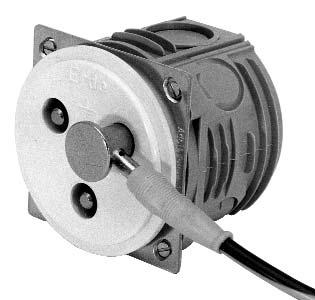
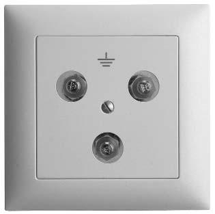
38 Wrap connections for potential compensation Art. No Art. No Art. No With cover plate, 86 x 86 mm, white. For mounting in NIS box (installation depth about 40 mm). With cover plate, 86 x 86 mm, white. For mounting in NIS box (installation depth about 40 mm). Front plate Ø 63 mm, white, without embedding box. For mounting in NIS box. Art. No Art. No Art. No Front plate Ø 63 mm, white, without embedding box. For mounting in NIS box. With cover plate, 88 x 88 mm, white. For mounting in NIS box (installation depth about 40 mm). With cover plate, 88 x 88 mm, white. For mounting in NIS box (installation depth about 40 mm). for appliance outlet combinations Art. No /B for appliance outlet combinations Art. No /S Usage example: grounding Art. No with NIS box and right-angle plug Art. No Clamp for conductors up to 16 mm 2 on back side - Woertz service: fitting of hospital ducts and under-window ducts for laboratories with sockets and NIS boxes
 for flush")


39 Connectors for potential compensation in laboratories, in medically used rooms, against static charges Sockets 1 2 Connectors with sprung sockets, Ø 6 mm, silver-plated, with lock. for mounting in dry rooms Plug-in sockets of nickel-plated brass, Ø 6 mm 1 Grounding plug 2 for three single-pole plugs Ø 6 mm Grounding plug for three single-pole right-angle plugs a) for flush mount b) for installation ducts c) for appliance outlet combinations Art. No Art. No Art. No /B Art. No Art. No Art. No /S 3 Grounding plug for three single-pole right-angle plugs 4 Grounding plug for three single-pole right-angle plugs 3 for flush mount type UP Edizio Uno 88 mm 88 mm 4 for flush mount type UP Edizio Due Art. No mm Art. No mm to be used for potential compensation, test boards, switchboards and experiment boards 4 5 type KST 6 AR-N with interlock Protected against unintended or erroneous disconnection. For 10 mm 2 strands. type POAG-KBT 6 DIN, according to DIN 42801, with special protection against cut (tested by TÜV). Socket body of nickel-plated brass, with gilded contact plate. For 4 and 6 mm 2 very flexible strands. 4 Plug 90 A Art. No Plug 5 Right-angle plug Art. No to be used for potential compensation, test boards, switchboards and experiment boards 6 Plug 90 A 6 type KST 6 N without interlock for 10 mm 2 strands. Art. No