Earth Brickwork Concrete Plain Radial Drum Roller Flap. fixed. Weirs Barrages. mobile. rockfills. Gravity butress Arch Arch-gravuty Cupola.
|
|
|
- Junior O’Connor’
- 5 years ago
- Views:
Transcription
1 Dams type 1
2 Weirs Barrages fixed mobile Earth Brickwork Concrete Plain Radial Drum Roller Flap embankment Earthfills rockfills Dams Concrete gravity Arch Gravity butress Arch Arch-gravuty Cupola 2
3 Dams Dams differ from all other major civil engineering structures in a number of important regards: every dam, large or small, is quite unique; foundation geology, material characteristics, catchment flood hydrology etc. are each sitespecific. dams are required to function at or close to their design loading for extended periods. dams do not have a structural lifespan; they may, however, have a notional life for accounting purposes, or a functional lifespan dictated by reservoir sedimentation. the overwhelming majority of dams are of earthfill, constructed from a range of natural soils; these are the least consistent of construction materials. dam engineering draws together a range of disciplines, e.g. structural and fluid mechanics, geology and geotechnics, flood hydrology and hydraulics, to a quite unique degree. the engineering of dams is critically dependent upon the application of informed engineering judgment. In summary, dam engineering is a distinctive, broadly based and specialist discipline. 3
4 Dams: embankments a dam constructed from natural materials excavated or obtained close by. The materials available are utilized to the best advantage in relation to their characteristics as an engineered bulk fill in defined zones within the dam section. The natural fill materials are placed and compacted without the addition of any binding agent, using high-capacity mechanical plant. Embankment construction is consequently now an almost continuous and highly mechanized process, weather and soil conditions permitting, and is thus plant intensive rather than labor intensive. Embankment dams can be classified in broad terms as being earthfill or rockfill dams. The division between the two embankment variants is not absolute, many dams utilizing fill materials of both types within appropriately designated internal zones. 4
5 5

6 Principal variants of earthfill and earthfill rockfill embankment dams (values of m are indicative only) 6

7 Principal variants of rockfill embankment dams (values of m are indicative only) 7
8 Merits 1. the suitability of the type to sites in wide valleys and relatively steepsided gorges alike; 2. adaptability to a broad range of foundation conditions, ranging from competent rock to soft and compressible or relatively greater susceptibility to damage or destruction by overtopping, with a consequent need to ensure adequate flood relief and a separate spillway, and vulnerability to concealed leakage and internal erosion in dam or foundation pervious soil formations; 3. the use of natural materials, minimizing the need to import or trans- port large quantities of processed materials or cement to the site; 4. subject to satisfying essential design criteria, the embankment design is extremely flexible in its ability to accommodate different fill materials, e.g. earthfills and/or rockfills, if suitably zoned internally; 5. the construction process is highly mechanized and is effectively continuous; 6. largely in consequence of 5, the unit costs of earthfill and rockfill have risen much more slowly in real terms than those for mass concrete; 7. properly designed, the embankment can safely accommodate an appreciable degree of deformation and settlement without risk of serious cracking and possible failure. 8
9 Disadvantages: 1. greater susceptibility to damage or destruction by overtopping, with a consequent need to ensure adequate flood relief and a separate spillway 2. vulnerability to concealed leakage and internal erosion in dam or foundation 9

10 Dams: Concrete Gravity dams. Buttress dams. Arch dams h Upstram facing 10

11 Dams: Concrete Gravity dams. A concrete gravity dam is entirely dependent upon its own mass for stability. The gravity profile is essentially triangular to ensure stability and to avoid overstressing of the dam or its foundation. Some gravity dams are gently curved in plan for aesthetic or other reasons, and without placing any reliance upon arch action for stability. Where a limited degree of arch action is deliberately introduced in design, allowing a rather slimmer profile, the term arched or arch-gravity dam may be employed. 11
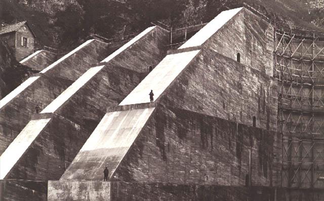
12 Dams: Concrete Buttress dams. In structural concept the buttress dam consists of a continuous upstream face supported at regular intervals by downstream buttresses. The solid head or massive buttress dam is the most prominent modern variant of the type, and may be considered for conceptual purposes as a lightened version of the gravity dam. 12
13 13
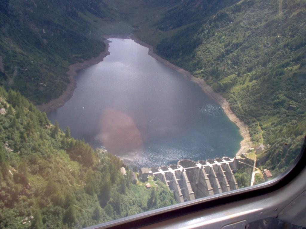
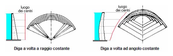
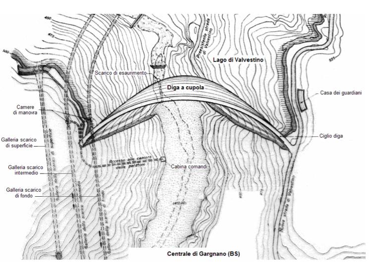
14 Dams: Concrete Arch dams. The arch dam has a considerable upstream curvature. Structurally it functions primarily as a horizontal arch, transmitting the major portion of the water load to the abutments or valley sides rather than to the floor of the valley. It is structurally more efficient than the gravity or buttress dam, greatly reducing the volume of concrete required. A particular derivative of the simple arch dam is the cupola or double curvature arch dam. The cupola dam introduces complex curvatures in the vertical as well as the horizontal plane. It is the most sophisticated of concrete dams, being essentially a dome or shell structure, and is extremely economical in concrete. Abutment stability is critical to the structural integrity and safety of both the cupola and the simple arch. 14
15 15
16 16
17 Merits 1. Arch and cupola dams excepted, concrete dams are suitable to the site topography of wide or narrow valleys alike, provided that a competent rock foundation is accessible at moderate depth (<5 m). 2. Concrete dams are not sensitive to overtopping under extreme flood conditions (cf. the embankment dam) 3. concrete dams can accommodate a crest spillway, if necessary over their entire length, provided that steps are taken to control downstream erosion and possible undermining of the dam. The cost of a separate spillway and channel are therefore avoided. 4. Outlet pipework, valves and other ancillary works are readily and safely housed in chambers or galleries within the dam. 5. The inherent ability to withstand seismic disturbance without catastrophic collapse is generally high. 6. The cupola or double-curvature arch dam is an extremely strong and efficient structure, given a narrow valley with competent abutments. 17
18 Disadvantages 1. Concrete dams are relatively demanding with respect to foundation conditions, requiring sound and stable rock. 2. Concrete dams require processed natural materials of suitable quality and quantity for aggregate, and the importation to site and storage of bulk cement and other materials. 3. Traditional mass concrete construction is relatively slow, being labor intensive and discontinuous, and requires certain skills, e.g. for formwork, concreting, etc. 4. Completed unit costs for mass concrete, i.e. cost per cubic meter, are very much higher than for embankment fills, typically by an order of magnitude or more. This is seldom counterbalanced by the much lower volumes of concrete required in a dam of given height. 18

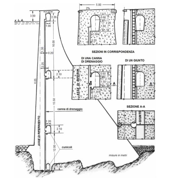
19 protect the facing upstream with a screen usually consists of a series of reinforced concrete vaults resting on the vertical axis and projecting pilasters set against the dam (Levy screen). Thus formed between the screens of vertical wells and the body of the dam, where water can flow without a permeation pressure to be channeled through a tunnel exhaust. The system is good but very expensive. Vaults (must face the hydro. loads) Internal face Cheaper and widespread is the system of drainage: it can almost be considered a transformation of the previous one and involves the construction of a series of vertical tube wells in the body of the dam, a small distance between them (1.5 3 m) and a few meters by facing upstream. The wells are owned by horizontal tunnels that collect the infiltrated water and feed it into a single tunnel through which we measure and the total discharge downstream of the seepage collected from the wells. This has the advantage of continuous surveillance of the behavior of the dam: every abnormal cracking gives rise to an increase of flow. 19
20 20
21 To prevent abnormal stresses due to thermal expansion caused by changes in the volume of the concrete during the intake and external temperature variations, is now the general custom build the dam with expansion joints, i.e. to build the dam for "independent pillars combined" the cavity and arm joints. These joints are arranged at distances of 30 to 40 meters, went so far as part of the foundation, the only way to the base. 21
22 Temporary joints used during the maturation of the concrete After the maturation they are filled with beton 22
23 Permanent joints (thermal variation between upstream and downstream faces ) few centimeters thick, sinusoidal trend. These strips are filled with bituminous material (tarred paper, glass wool) or bitumen. One concern is to prevent the infiltration of water, therefore it should be put ahead of the joints 23


24 1. a copper plate is placed between the concrete slab and that works. 2. leave a lozenge in the concrete and then fill it with a concrete block, this block is pushed from the water and prevents water from entering 24
25 25