QUALIFICATION AND APPLICATION OF IN-SERVICE INSPECTION OF VVER-440 CONTROL ROD DRIVE PROTECTION PIPES
|
|
|
- Pamela Dalton
- 5 years ago
- Views:
Transcription
1 QUALIFICATION AND APPLICATION OF IN-SERVICE INSPECTION OF VVER-440 CONTROL ROD DRIVE PROTECTION PIPES Krunoslav Markulin, Matija Vavrous INETEC-Institute for Nuclear technology, Croatia Jani Pirinen, Petri Luostarinen Fortum Power and Heat Oy, Finland Abstract Reliability of operation of nuclear power plant is essential for safe and efficient production of electrical power. Maintenance activities are regularly performed during outages on various power plant components. Maintenance of primary circuit components is especially demanding due to safety importance of these components and time constraints that service of such components require. Non-destructive inspection methods are used as a tool for checking the primary circuit components including VVER reactor pressure vessel head control rod drive protection pipes. As control rod drive protection pipes present reactor coolant boundary, integrity of this boundary must be maintained to avoid threats to environment and to keep production capacities. VVER-440 control rod drive protection pipe includes multiple welds and its configuration presents a challenge for successful inspection, especially when applied from inner surface. Requirements for performance of such inspection are defined by applicable standards and inspection capability must be verified through extensive qualification process. INETEC-Institute for Nuclear Technology, as a company specialized in NDT applications developed automatized inspection system and methodology for control rod drive protection pipe inspection from the inside surface. Such system was subjected to qualification and successfully qualified in accordance with ENIQ and STUK YVL Regulatory guide requirements. Qualified system, methodology and personnel performed actual on-site inspections in Louisa Power Plant. This article will present in detail the challenges, issues and lessons learned both during qualification stage and on-site inspection stage of control rod drive protection pipes in-service inspection.
2 1. Introduction Control rod drive protection pipes are element of reactor pressure vessel head assembly characteristic for VVER-440. Reactor pressure vessel head and body on the control rod drive penetration tube are made from carbon steel but inside penetration tube is additional pipe that is made from stainless steel and has purpose to protect the penetration tube. Generally, control rod drive protection pipe is stainless steel pipe that includes 4 or 5 circumferential welds, depending on the design. There are two different designs of the CRD protection pipes, original Russian construction and Czech construction manufactured by Skoda with Russian license. Three welds are circumferential butt welds (welds no. 1-3) and one weld is dissimilar metal weld (DMW, weld no. 4 (Russian), weld no. 4/P (Skoda)) between flange and protection pipe. One weld (weld no. 4a (Russian), 5/P (Skoda)) is connection weld between thermal sleeve and DMW. DMW and connection weld of thermal sleeve are considered in the flaw and detection target evaluation as weld no. 4. Figure 1 Control rod drive protection pipe weld locations Following table presents dimensions of diameter and wall thickness of CRDPP welds. Table 1 Dimensions of CRDPP welds and wall thickness Inspection object OD/ID [mm] Wall thickness[mm] Weld 1 273/ Weld 2 273/ Weld 3 138/ Weld 4 (4/P) 138/ Weld 4a (5/P) 110/103 (138/103) 3.5 As control rod drive protection pipe during exploitation presents reactor coolant boundary, periodic control of CRDPP and its welds is necessary to ensure reliability of operation of CRDPP component and VVER power plant as whole. Due to that necessity, Loviisa Power Plant, VVER power plant type VVER-400 and its owner Fortum Heat and Oy requested from INETEC-Institute for Nuclear Technology to develop inservice inspection method that will be applied during annual outages at Loviisa Power Plant. As CRDPP inspection activity is safety related activity, detailed process of qualification before the actual inspection was necessary to verify capabilities of selected inspection method against requirements for inspection [1].

3 Based on operating experience from Loviisa Power Plant and other similar power plants degradation mechanisms that were identified as specific for CRDPP component or similar components were circumferential fatigue or corrosion fatigue flaws initiating from geometrical discontinuity or the manufacturing defect such as root defects of the welds. In the DMW, weld no. 4 (4/P) on CRDPP, based on experience, flaws are expected to grow along the fusion line and most probably further propagate to direction of the ferrite nozzle material. Besides these specific flaws, other postulated defects (defects identified in other components but not in CRDPP) were circumferential fatigue cracks initiating from root of the weld due to possible root defect or geometrical discontinuity expected direction of growth towards austenitic weld material and/or along austenitic weld/buttering fusion line, and axial fatigue corrosion cracking and circumferential fatigue or corrosion cracking of welds 1-3 of CRDPP. 2. Inspection method In order to achieve maximum efficiency regarding inspection time and applied resources during inservice inspection, selected inspection method for VVER-440 CRDPP was ultrasonic and eddy current inspection simultaneously from the inside surface of the control rod drive protection pipe. INETEC-Institute for Nuclear Technology developed a concept of inspection from the inside based on a long pole with two assemblies: one assembly carrying probes for inspection of ID237 welds of the CRDPP and the other assembly, lower sled, carrying probes for inspection of ID103/106 welds of the CRDPP. General presentation of the pole is available on the Figure 2. Figure 2 Control rod drive protection pipe inspection tool developed by INETEC For the both upper and lower assembly multiple probes were selected and implemented in assembly with eight probes, seven ultrasonic probes and one eddy current probe. Eddy current inspection method was selected for inspection of surface defects while ultrasonic inspection method was selected for surface and volumetric inspection, including OD surface of the CRDPP. Eddy current inspection is based on single eddy current probe that includes cross-wound coils. Three cross wound coils were used creating eddy current array that enables covering both circumferentially and axially, and respectively, enables same sensitivity in circumferential and axial scanning patterns. Additionally, this design eliminates need for the rotation of the eddy current array probe when changing the scanning pattern. Probes of different dimensions but with same coils and coil arrangement were used for larger, ID237 welds and smaller, ID103/106 welds. Figure 3 Eddy current array probe for CRDPP inspection


4 Ultrasonic inspection is based on ultrasonic contact inspection technique with application of multiple probes oriented for axial and circumferential inspections. For scanning of larger ID237 welds the creep wave and 45 degree dual element probes are applied enabling two directional examinations during the both axial and circumferential scans. For scanning of smaller ID106/103 welds creep wave probe, 45, 60, and 70 degree dual element probes are applied, also enabling two directional examinations during axial and circumferential scan. This way four directional coverage of inspection volume of welds 1 through 4 of CRDPP was achieved. With applied configuration, there is no need for rotation of sleds or probes during the scanning, so once the tool in installed in the control rod drive protection pipe, the axial and circumferential scans of all welds can be performed without any modification on the tool. This aim of such solution was to reduce inspection time, and this solution was proven to be successful as achieved inspection times were considerably less than expected. a) b) Figure 4 CRDPP inspection tool sled assembly: a) weld ID 103/106 b) weld ID 237 For the ultrasonic inspection, coupling with inspection surface is achieved by water. Bottom of the CRDPP is plugged with specially developed plug that enables that inside of the protection pipe is filled with water. Long handled pole is used for lowering of plug at exact position and to lock it. After the inspection of selected CRDPP is completed, water is pumped out of the inspected pipe to another pipe that needs to be inspected. After that plug is removed and moved to the next protection pipe. Figure 5 CRDPP plug

5 In order to additionally strengthen the surface inspection capability, an enhanced visual inspection method was also applied, but separately to eddy current and ultrasonic inspection as independent inspection system. Visual inspection system is based on assembly that is pulled from the inside surface while recording the surface of the CRDPP. The assembly includes 4 legs with wheels that enable smooth movement of the assembly without affecting the quality of the surface. Since CRDPP surface is highly reflective, it is possible to change the angle of imaging and lightening conditions during inspection. Visual testing is carried out in an almost perpendicular direction to the surface of the object up to the viewing angle by ±60 from the perpendicular line taking into account the minimization of reflections. The rate of camera movement is adapted to the inspection object and magnification ratio so that the image always remains sharp. Figure 6 CRDPP Visual inspection tool 3. Qualification process As detailed input was prepared for the inspection process same input document defined in details qualification requirements. Besides all information that was necessary for the preparation of inspection, input information also defined inspection method qualification requirements for: Qualification level Inspection personnel Inspection volume Detection targets Defect positioning, length and depth Defect positioning axially and radial

6 Figure 7 CRDPP inspection and qualification Input Information document prepared by Fortum Qualification process was performed in accordance with the qualification of non-destructive inservice inspections of Finnish nuclear power plants [3], qualification practice based on ENIQ inspection methodology. Qualification proceedings were divided into open trials and blind trials. For each type of trails specimens with various flaws (different nature, dimensions and location of the flaws) were made available by Fortum. Available open trial specimens covered all types of welds, and included sufficient amount of flaws for reliable calculation of RMS factor and statistical processing of results. Figure 8 present examples of specimens for open trials. Scanning on the open samples was performed by the same manipulator to be used on site but with partial assembly that included both upper and lower sled and scanning mechanism. During open trails all open samples were scanned and analyzed in front of the Qualification Body, and for each flaw its sizing had to be justified and presented that is performed in accordance with the inspection procedure. As YYL guide and Finnish qualification procedure qualification guidelines were based on ENIQ methodology, the Technical Justification was utilized in order to additionally strengthen the qualification. Technical Justification is document that includes all evidences that will be used that selected inspection technique meets defined requirements. Technical Justification for this case of qualification included evidence in form of theoretical evidence, experience from similar inspection previously performed and laboratory studies. During laboratory testing various studies have been prepared i.e. influence of skew and tilt angle on flaw detection and sizing, influence of probe lift-off on flaw detection and sizing, influence of probe tilt and change of beam angle on flaw detection and sizing, dependency of scanning path on detection and other similar studies.


7 Figure 8 Examples of CRDPP open trial specimens Technical Justification, together with results of open trials, which were performed in front of the Qualification Body were evidence to assure that selected equipment for ultrasonic and eddy current testing when applied in accordance with prepared ultrasonic and eddy current inspection procedure. After open trials were successfully completed, blind trials phase was performed. Blind samples, which covered all types of welds, were scanned by INETEC team under close surveillance of the Qualification Body. A selected group of inspection analysis personnel attended to the blind testing with goal to detect and size flaws in blind samples with satisfying detection rate and length and depth sizing accuracy. Blind testing was successful and sufficient number of personnel was qualified that Inspection Company INETEC could perform inspection during outages 2010 and Figure 9 Scanning of open trial specimens during qualification 4. On-site inspection performance During the outage of Loviisa Power Plant Unit 2 in September 2010 INETEC Inspection Company performed the first CRDPP inspection. Inspection included eddy current and ultrasonic testing in parallel and separate inspection with visual testing. Selected non-destructive testing equipment including manipulator for inspection was applied without any significant issues and overall inspection was completed in less time than initially planned.
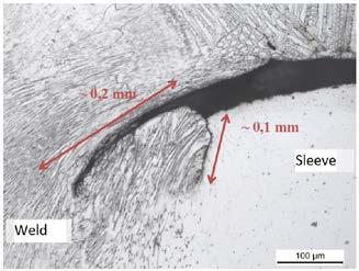
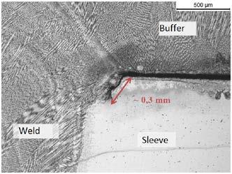
8 A number of valuable lessons were learned during the performance of the first of two scheduled inspections. During the inspection of Skoda design CRDPP a minor difference in the design and input documentation was determined. According to the design drawings location of the weld 3 was not at the same axial location when measured from the top flange. Exact location of the weld was determined by specific weld material noise that can be observed in ultrasonic data due to the austenitic nature of the weld 3. During the ultrasonic inspection one subsurface indication on weld 4a was detected on one of Russian design of CRDPP. The found indication was circumferentially oriented and consisted of two parts located under 180 to each other. The detected indication could not be compared with any defect from open trials, however, it was sized and evaluated against the reference criteria and found to be acceptable. As a result, the power plant owner Fortum decided to replace the subject CRDPP with a new one and to perform destructive testing in order to gain additional information on weld 4, and also to compare nondestructive with destructive testing so as to confirm suitability of in-service inspection qualification. 5. Additional external inspection and destructive testing Before destructive testing an external inspection was performed by two separate groups with different ultrasonic techniques for the sample removed from CRDPP. Samples were also x-ray inspected. One of the used UT techniques was PDI-technique, TR Matrix PA probe and sectorial scan degrees longitudinal wave. Another UT techniques used by the second group were different TR- techniques, shear- and longitudinal wave. As a conclusion, there were no clear defect indications according the inspections performed. The aim on destructive testing (DT) study was to examine the dissimilar metal weld joint of CRDPP in order to find possible defects. The sample locations (figure 10) for this DT study were determined based on the UT results reported by Inetec. About 60mm wide slice including dissimilar weld were sawed from the CRDPP. Further samples were cut from determined location for metallurgical studies. Significant defects were not observed in the studied samples. However, small defects and a clear 0,2mm - 1mm gap between the buffer weld and the thermal sleeve were detected in the cross sections that were cut around the clearest indication areas reported by INETEC. Also from sample can be seen, that thermal sleeve was not located eccentric. Small welding defects, cracks or combinations of those two were observed in all of the samples (max. about 0.5 mm), excluding sample 3. In the samples prepared from the so called stronger indication area ( ), i.e. samples number 1 (277.3 ) and 2 (298.1 ), lack of fusion was observed in each of the specimens in the joint of the thermal sleeve. Samples taken from stronger indication area are presented in figures 11 to 13. In addition, minor crack growth during operation was observed in the both cases.


")
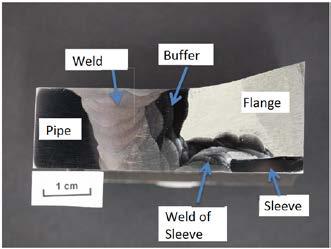
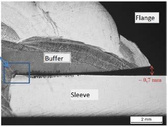
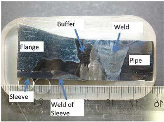
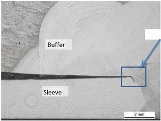

9 Figure 10 Cutted cross section (left), DT Sample locations (right) Figure 11 Additional Sample 2 (273,3 ) Figure 12 Sample 1 (277,3 ) Figure 13 Additional Sample 1 (281,3 ) 6. Additional qualifications

10 As a number of question arose from information that were provided by destructive testing Qualification Body and Fortum required that additional qualification is to be performed to furthermore validate inspection capabilities, with emphasize on cases that were determined as worst case defects, in accordance with ENIQ approach. Two samples were prepared, one mainly for eddy current inspection verification and both for ultrasonic inspection verification. Eddy current additional open sample included flaws located in corner of the weld root for weld 1. As probe is tilted and in liftoff when scanning across corner of the root of the weld, caused decreased inspection sensitivity including detection and sizing capability. However, as scanning perpendicular to the weld and scanning parallel to the weld was used during inspection and design of eddy current probe included coils sensitive to both directions of flaws, detection was possible. During scan parallel to the weld, coils sensitive to flaws parallel to the weld successfully detected and sized all flaws as shown on Figure 14. This proved the assumption of the Technical Justification regarding the worst case defect for eddy current inspection. Figure 14 Eddy current testing weld 1 root worst case As weld root and lift-off due to it was also identified as worst case for ultrasonic inspection, ultrasonic inspection was also performed on this sample and all flaws, both located on ID on weld root and OD were successfully detected and sized. For ultrasonic inspection, one additional open test sample was made for DMW (weld 4) and connection weld between thermal sleeve and DMW (weld 4a) configuration based on the inspection finding since by its configuration presents very challenging inspection object. The additional test sample included OD flaws in dissimilar pipe to buttered flange weld 4 and sleeve weld to cladding 4a. All flaws were successfully detected and sized, as shown on Figure 15, with the similar response to on site finding.

11 Figure 15 Ultrasonic testing DMW 4 OD flaws worst case 7. Conclusions Presented cycle of in-service inspection process, from beginning of work and through qualification process and application of inspection methods on actual site and verification of inspection finding by destructive testing and additional qualification, shows ideal approach to ensuring nuclear safety. As presented, requirements for each inspection parameter (inspection technique, equipment, personnel, procedure) were determined by the Customer Inputs and it was required that verification of inspection parameters against Input Information requirements is performed through the qualification. By completing the qualification it was ensured that selected inspection company provided exactly the type of inspection with exact parameters that were asked for. During the actual on site examination, non-destructive testing was performed with exact parameters that were qualified. Moreover, findings of the inspection resulted in significant repair/replacement activity which was later followed with destructive testing to verify the inspection method. Additional qualification was performed to verify inspection capabilities versus worst case assumptions. In all stages, power plant requirements were successfully met despite all challenges and final result was in-service inspection where for each step and parameter there is traceable verification. By such approach quality of CRDPP inspection activity was assured to be at very high level and purpose of increasing the nuclear safety and ensuring safe power plant operation was achieved. 8. References 1. FNS LO1-K , INPUT INFORMATION: CRD Protection Pipe, A. Neuvonen, J. Pirinen, 13 April YVL GUIDE YVL 3.8, NUCLEAR POWER PLANT PRESSURE EQUIPMENT: In-service inspection with non-destructive testing methods, 3rd edition, STUK - Radiation and Nuclear Safety Authority, Finland, 22 September The qualification of non-destructive in-service inspections of Finnish nuclear power plants. Qualification of personnel. SP8, Inspecta, Finland. 4. Technical Justification for the Loviisa Power Plant Control Rod Drive Protection Pipe Examination, M. Vavrous, K. Markulin, June 20, 2012