Architectural Technology & Construction Management
|
|
|
- Shauna Curtis
- 5 years ago
- Views:
Transcription
1 Architectural Technology & Construction Management
2 Drain and sewer TCU 2016
3 Sewer plan Drain water (page 18-21) Waste water (page 3-6) Rain water (page 14-16) Above pages refer to Guidelines for Design and Project Planning Definition: Drain water: The water content in soil (causing pressure on construction and soil) to be reduced or removed completely. Rain water: Water collected by roof and outdoor built areas (Not soil surface) Waste water: Water from i.e. bathroom, toilets, kitchen sink, and floor drains to be discharged.
4 Drain Houses shall be built in such a way that surface water, ground water and earth moisture do not cause damage. (Building regulation 2010) Before you start: Soil conditions have to be determined by geotechnical analysis. Groundwater conditions have to be determined and the water level has to be found. A perimeter drain can be left out in houses where the surface of the floor deck is more than 300mm above the external ground level. (Building regulation 2010)
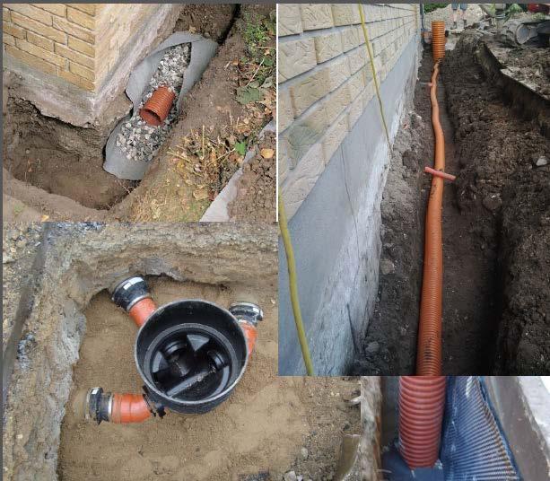
5 Placement of drain pipe Terrain Slope Soil Foundation Filter material (min.0,1 m around the pipe) Drain pipe (minimum fall 3 ) Maximum excavated depth
6 Drain water Frost free depth drain pipes: 600 mm next to a heated building 750 mm next to a not heated building The highest bottom level should be at least 0.3 m below the construction part to be drained. (i.e. capillary breaking layer) Slope (without calculations): slope 3-5 Pipe size Drain pipe min Ø70 normally Ø80 Gully size Min. 300
7 Placement of drain water gully's All bends must be able to be cleaned from both sides of an access well. At least a gully every second bend.
8 Drain

 Bathroom")


9 Waste water Come from: Kitchen (Kitchen sink, dishwasher) Bathroom (Sink, bathtub, shower, floor drain, bidet) Toilet Washing machine Floor drains (see examples below)
10 Waste water Frost free depth 750 mm frost free depth Slope (without calculations) Min. slope 20 (without calculations) Min. slope 12 after first toilet (without calculations) Gully size Cleaning gully min. 315 mm but 425 is easier to clean Pipe size Pipe size min. 100 mm for plastic pipes 110 mm


11 Waste water in the kitchen water trap
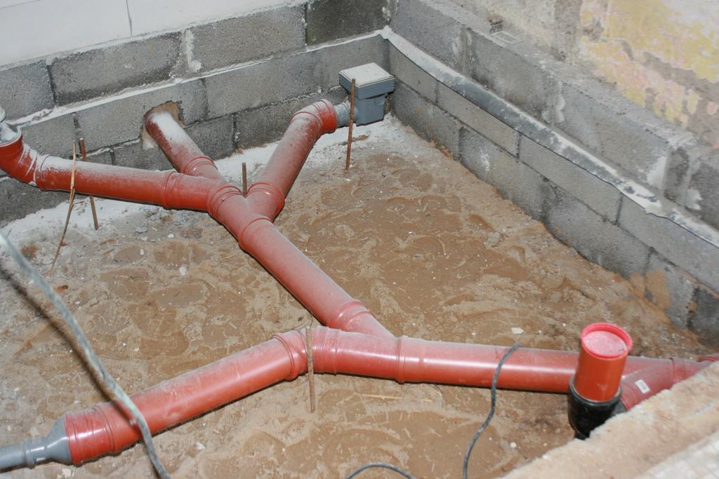
12 Placement of pipes
13 Laid pipelines Double branch pipes must not be used! NOT OKAY! OK!! 45 - connections are normally used
14 Connection to existing pipes Side connection is recommended => always use it! Stand pipe Laid pipe
15 Rain water Roof Outdoor built areas


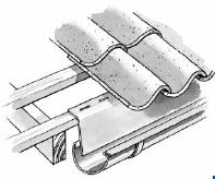
16 Rain water gutter and down pipe

17 Wells and down pipes
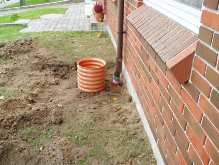
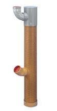
18 Roof downpipe connection to gully Drain well (gully)(circular) with water trap, tight cover and roof downpipe Cast-in bend With sand/sludge separator Dry pipes A "dry" pipe is a pipe where the water has not yet passed a sand trap. Soil coverage in garden areas and the like should be at least 30 cm, and the slope of the pipe must be min. 20, so there is reasonable assurance that the pipe is self-cleaning.
19 Rain water Frost free depth 750 mm Dry pipe mm Slope (without calculations) Min. slope 10 rain water pipes after first sand catch Min. slope 20 for dry pipes Pipe size Minimum 100 mm, but for plastic pipes Ø110 Gully size: 200 mm if there is a single run 315 mm if there are several runs
20 Rainwater gully's with sand catch Indicate the gully IL xx,xx CL xx,xx FLxx,xx Indicate the down pipe (DP) FL : Flow level given in meter (m) CL : Cover level - given in meter (m) IL : Inlet level given in meter (m) Indicate that it is at rain water gully with water trap and sand catch.
21 SYMBOLS Waste water Rainwater Dry rainwater pipe Drain pipe
22 Recommended distance between building and pipes outside the building

23 Waste water pipes
24 Information on drawings Access gully = Inspection gully = Flushing gully Dimension minimum 315 mm, 425mm wells are often preferred as they are easier to clean. CL xx,xx BL xx,xx BL : Bottom level given in meter (m) CL : Cover level - given in meter (m)

25 Infiltration trench
26 Example of a sewer plan (Revit Architecture page 179)
27 Question A Design the sewer system for your building designed during the first workshop based on rules and guidelines including wastewater, rainwater and drain (literature: present PDF Sewer plan TCU 2016 and Guidelines for Design and Project Planning Note: Only a plan drawing is to be carried out.
28 Question B Calculate the missing levels at the inspection gullies.
29 Question C Given: Terrain level: Floor level: To do: Please indicate pipe dimensions and slopes of all pipes on your sewer plan carried out in assignment 1 Based on the above levels please indicate pipe levels at foundations, gullies and connections. (sketches/cross sections maybe helpful) References: PDF page 20 and 24