CITY OF LOS ANGELES CALIFORNIA
|
|
|
- Shannon Burns
- 5 years ago
- Views:
Transcription

1 BOARD OF BUILDING AND SAFETY COMMISSIONERS HELENA JUBANY PRESIDENT VAN AMBATIELOS VICE-PRESIDENT E. FELICIA BRANNON VICTOR H. CUEVAS GEORGE HOVAGUIMIAN CITY OF LOS ANGELES CALIFORNIA ERIC GARCETTI MAYOR DEPARTMENT OF BUILDING AND SAFETY 20 NORTH FIGUEROA STREET LOS ANGELES, CA 9002 RAYMOND S. CHAN, C.E., S.E. SUPERINTENDENT OF BUILDING INTERIM GENERAL MANAGER HILTI, Inc. RESEARCH REPORT: RR S. 22 E. Avenue (CSI # ; ; 0 0 2) Tulsa, OK 7446 BASED UPON ICC ES EVALUATION Attn: Andrew T. Liechti REPORT No. ESR-72 (98) REEVALUATION DUE DATE: August, 206 Issued date: May, 204 Code: 204 LABC GENERAL APPROVAL Revaluation - Hilti Low-Velocity Power Driven Track Fasteners DETAILS The Power Driven Fasteners are approved when in compliance with the description, identification and conditions of use in Evaluation Report No ESR-72, reissued August, 20, of the ICC Evaluation Service, Incorporated. That report, in its entirety, is attached and made a part of this general approval. The parts of Report No.ESR-72 marked by the asterisks are modified by the Los Angeles Building Department from this approval. The approval is subject to the following conditions:. The fasteners shall not be used to resist seismic loads, except when used with architectural, electrical, or mechanical components as described in Section..4 of ASCE 7-0 and as follows: a) Concrete base materials: The Hilti fasteners installed in concrete may be used to support distributed systems and distribution systems where the service load on any individual fastener does not exceed the lesser of 90 lbf or the published allowable load shown in Tables 2, and 4 of the attached ICC-ES ESR-72, as applicable. b) Steel base materials: The Hilti fasteners installed in steel may be used where the service load on any individual fastener does not exceed the lesser of 20 lbf or the published allowable load shown in Table of the attached ICC-ES ESR-72. RR 2662 Page of LADBS G- (Rev.02/20/204) AN EQUAL EMPLOYMENT OPPORTUNITY - AFFIRMATIVE ACTION EMPLOYER
2 Hilti, Inc. RE: Hilti Low-Velocity Power Driven Track Fasteners c) For interior, nonstructural walls that are not subject to sustained tension loads and are not a bracing application, the power-driven fasteners may be used to attach steel track to concrete or steel in all Seismic Design Categories. In Seismic Design Categories D, E and F, the allowable shear load due to transverse pressure shall be no more than 90 pounds when attaching to concrete; or 20 pounds when attaching to steel. Substantiating calculations shall be submitted addressing the fastener- to-base-material capacity and the fastener-to attached-material capacity. Interior nonstructural walls are limited to locations where bearing walls, shear walls or braced walls are not required by the approved plans. The design load on the fastener must not exceed the allowable load established in the attached ESR-72 for the concrete or steel base material. 2. The fasteners are only allowed to anchor non-building components including but not limited to drywall tracks, sprinkler pipes, furniture, cabinets, sheet metal duct work, electrical conduits, cable trays, cables, lighting, wood sill plates, acoustical ceiling, light gauge framing, and non-bearing-non-structural interior partitions. The fasteners shall not be used in cracked concrete. 4. The allowable values listed in the attached ICC-ES ESR 72 and tables are for the fasteners only. Connected members shall be checked for their capacity (which may govern).. Fasteners are manufactured and identified in accordance with report ESR The fasteners shall be limited to dry, interior locations. 7. Fasteners shall be installed in accordance with this report and the manufacturer s published installation instructions. In the event of conflicts between this report and the manufacturer s published installation instructions, this report shall govern. 8. The allowable tension and shear values shall comply with Section 4. of ESR-72. Calculations demonstrating that the applied loads are less than the allowable loads described in this report shall be submitted to the code official for approval. 9. The use of fasteners attaching cold-formed-steel tracks to foundations shall comply with section 4. of ESR-72 RR 2662 Page 2 of
3 Hilti, Inc. RE: Hilti Low-Velocity Power Driven Track Fasteners DISCUSSION The report is in compliance with the 204 Los Angeles City Building Code. The approval is based on tests in accordance with the ICC-ES Acceptance Criteria for Fasteners Power-driven in Concrete, Steel, and Masonry Elements (AC-70), dated February 20. Addressee to whom this Research Report is issued is responsible for providing copies of it, complete with any attachments indicated, to architects, engineers and builders using items approved herein in design or construction which must be approved by Department of Building and Safety Engineers and Inspectors. This general approval will remain effective provided the Evaluation Report is maintained valid and unrevised with the issuing organization. Any revisions to the report must be submitted to this Department, with appropriate fee, for review in order to continue the approval of the revised report. This general approval of an equivalent alternate to the Code is only valid where an engineer and/or inspector of this Department has determined that all conditions of this Approval have been met in the project in which it is to be used. ALLEN PEERY, Chief Engineering Research Section 20 N. Figueroa St., Room 880 Los Angeles, CA 9002 Phone Fax VC RR2662/MSWord200 R04/26/4 C2/04.2.6/9/92/207 Attachments: ICC-ES Evaluation Report No. ESR-72 (6 Pages) RR 2662 Page of
4 ICC-ES Evaluation Report (800) (62) ESR-72 Reissued August, 20 This report is subject to renewal September, 20. A Subsidiary of the International Code Council DIVISION: CONCRETE Section: 0 00 Concrete Accessories Section: Concrete Anchors DIVISION: MASONRY Section: Masonry Anchors DIVISION: METALS Section: Metal Fastenings DIVISION: FINISHES Section: Fasteners REPORT HOLDER: HILTI, INC. 400 SOUTH 22nd EAST AVENUE TULSA, OKLAHOMA HNATechnicalServices@hilti.com EVALUATION SUBJECT: HILTI LOW-VELOCITY POWER-DRIVEN S.0 EVALUATION SCOPE Compliance with the following codes: 202 International Building Code (IBC) 202 International Residential Code (IRC) 2009, 2006 and 200 IBC* 2009, 2006 and 200 IRC* *Codes indicated with an asterisk are addressed in Section 8.0. Property evaluated: Structural 2.0 USES Hilti low-velocity power-driven fasteners are used to attach light-gage cold-formed steel framing and architectural, electrical and mechanical components to concrete, sandlightweight concrete, metal deck panels with sandlightweight concrete fill, concrete masonry units (CMUs) and steel-base materials. The fasteners are alternatives to the cast-in-place anchors described in IBC Section908 for placement in concrete; the embedded anchors described in Section 2..4 of TMS 402/ACI 0/ASCE (which is referenced in IBC Section 207) for placement in grouted masonry; and the welds and bolts used to attach materials to steel, described in IBC Sections and , respectively. The fasteners may be used where an engineered design is submitted in accordance with IRC Section R DESCRIPTION. General: Hilti low-velocity power-driven fasteners are manufactured from hardened steel complying with the manufacturer s quality documentation... X-EGN, X-GN and X-GHP: The X-EGN fastener is a gas-driven fastener for installation into steel. The X-GN fastener is a gas-driven fastener for installation into concrete, CMUs, and concrete-filled metal deck panels. The X-GHP fastener is a gas-driven fastener for installation into steel, concrete, and concrete-filled metal deck panels. All fastener head diameters are inch (6.8 mm), and the fasteners have a tapered smooth shank with a nominal diameter at the base of 0.8 inch (.0 mm). The X-EGN and X-GHP fasteners have a 2-to-0-micron zinc finish, and the X-GN fastener is zinc-plated to ASTM B6, SC, Type III. The fasteners are collated into plastic strips of ten fasteners each...2 X-C: The X-C fastener is a powder-actuated fastener for installation into concrete, CMUs, and concretefilled metal deck panels. X-C fasteners have a shank diameter of 0.8 inch (. mm). The fastener is zincplated to ASTM B6, SC, Type III... X-C22P8TH: The X-C22P8TH fastener is a powder-actuated fastener for installation into concrete and concrete-filled metal deck panels. It has a shank diameter of 0.8 inch (. mm) and is supplied with a premounted steel tophat washer and a plastic washer. The fastener is zinc-plated to ASTM B6, SC, Type III...4 X-C20 THP: The X-C20 THP fastener is a powderactuated fastener for installation into sand-lightweight concrete and concrete-filled metal deck panels. It has a shank diameter of 0.8 inch (. mm) and is supplied with a premounted plastic tophat washer. The fastener is zincplated to ASTM B6, SC, Type III... X-S THP: The X-S THP fastener is a powderactuated fastener for installation into steel. It has a shank diameter of 0.4 inch (.7 mm) and is supplied with a premounted plastic tophat washer. The fastener is zincplated to ASTM B6, SC, Type III...6 X-S6P8TH: The X-S6P8TH fastener is a powder actuated fastener for installation into steel. It has a shank diameter of 0.4 inch (.7 mm) and is supplied with a premounted steel tophat washer and a plastic washer. The fastener is zinc-plated to ASTM B6, SC, Type III. ICC-ES Evaluation Reports are not to be construed as representing aesthetics or any other attributes not specifically addressed, nor are they to be construed as an endorsement of the subject of the report or a recommendation for its use. There is no warranty by ICC Evaluation Service, LLC, express or implied, as to any finding or other matter in this report, or as to any product covered by the report. Copyright 20 Page of 6 000
5 ESR-72 Most Widely Accepted and Trusted Page 2 of 6.2 Materials:.2. Normal-weight Concrete: Normal-weight concrete must be stone-aggregate and comply with IBC Chapter 90 or IRC Section R402.2, as applicable. The minimum concrete compressive strength at the time of fastener installation is noted in Table Sand-lightweight Concrete: Lightweight concrete must be sand-lightweight and must comply with IBC Chapter 9. The minimum concrete compressive strength at the time of fastener installation is noted in Tables and Concrete Masonry Units (CMUs): CMUs must be minimum 8-inch-thick (20 mm), normal-weight or lightweight block, complying with ASTM C90. Mortar must comply with ASTM C270 Type N (minimum) in accordance with IBC Section 20.9 or IRC Section R607, as applicable. Grouted concrete-masonry construction must be fully grouted and must have minimum prism strength, f m, of,00 psi (0. MPa) at the time of fastener installation. Grout must comply with Article 2.2 of TMS 602/ACI 0./ASCE 6 (referenced in IBC Section 20.) or IRC Section R609.., as applicable, as coarse grout..2.4 Steel: Structural steel used in supports must comply with the minimum strength requirements of ASTM A6, ASTM A72 Grade 0 or ASTM A992, and must have minimum yield and tensile strengths and thickness as noted in Table..2. Steel Deck Panels: Steel deck panels must comply with a code-referenced material standard and have the minimum thickness and minimum yield strength noted in Tables and 4. See Figures through for panel configuration requirements. 4.0 DESIGN AND INSTALLATION 4. Design: 4.. Allowable Loads: The allowable tension and shear loads for fasteners installed in structural steel are shown in Table. The allowable tension and shear loads with required embedment depths, for fasteners installed in normal-weight concrete, are shown in Table 2. The allowable tension and shear loads for fasteners installed in sand-lightweight concrete are shown in Table. The allowable tension and shear loads for fasteners installed through steel deck panels into sand-lightweight concrete fill are shown in Tables and 4. The allowable tension and shear loads with required embedment depths for fasteners installed in hollow and grouted concrete-masonry construction, are shown in Table. The stress increases and load reductions described in IBC Section 60. are not allowed for wind loads acting alone or when combined with gravity loads. No increase is allowed for vertical loads acting alone. Allowable loads apply to the connection of the fastener to the base material only. Design of the connection to the attached material must comply with the applicable requirements of the IBC. Allowable loads for fasteners subjected to combined shear and tension forces are determined by the following formula: (p/p a ) + (v/v a ) where: p = Actual tension load, lbf (N). P a = Allowable tension load, lbf (N). v = Actual shear load, lbf (N). V a = Allowable shear load, lbf (N) Seismic Considerations: Use with Structural Components: Resistance to seismic loads is outside the scope of this report. Therefore, the suitability of the Hilti fasteners for use with structural components that are subjected to seismic loads is outside the scope of this report Use with Nonstructural Components: Seismic load resistance is outside the scope of this report, except when use is with architectural, mechanical and electrical components described in Section..4 of ASCE 7, and as follows: Concrete base materials: The Hilti fasteners installed in concrete may be used to support distributed systems and distribution systems where the service load on any individual fastener does not exceed the lesser of 90 lbf (400 N) or the published allowable load shown in Tables 2, and 4, as applicable. Steel base materials: The Hilti fasteners installed in steel may be used where the service load on any individual fastener does not exceed the lesser of 20 lbf (2 N) or the published allowable load shown in Table. For interior, nonstructural walls that are not subject to sustained tension loads and are not a bracing application, the power-driven fasteners may be used to attach steel track to concrete or steel in all Seismic Design Categories. In Seismic Design Categories D, E, and F, the allowable shear load due to transverse pressure shall be no more than 90 pounds (400 N) when attaching to concrete; or 20 pounds (,2N) when attaching to steel. Substantiating calculations shall be submitted addressing the fastener-to-base-material capacity and the fastener-to-attached-material capacity. Interior nonstructural walls are limited to locations where bearing walls, shear walls or braced walls are not required by the approved plans. The design load on the fastener must not exceed the allowable load established in this report for the concrete or steel base material. 4.2 Installation: The fasteners must be installed in accordance with this report and the Hilti, Inc., published installation instructions. A copy of these instructions must be available on the jobsite at all times during installation. Installation must be limited to dry, interior locations. Fastener installation requires the use of a low-velocity power-actuated tool in accordance with Hilti, Inc., recommendations. Installers of powder-actuated fasteners must be certified by Hilti, Inc., and have a current, Hiltiissued, operator s license. Installers of gas-driven fasteners do not require an operator's license. When installation is in steel, minimum spacing between fasteners is inch (2 mm) on center, and minimum edge distance is / 2 inch (2.7 mm). Unless otherwise noted, when installation is in normal-weight and sand-lightweight concrete, minimum spacing between fasteners is 4 inches (02 mm) on center and minimum edge distance is inches (76 mm). Unless otherwise noted, concrete thickness must be a minimum of three times the embedment depth of the fastener. For concrete masonry units, the minimum fastener spacing is 8 inches (20 mm), and the minimum edge (boundary) distance is 8 inches (20 mm), with no more than one power-driven fastener installed per individual CMU cell. For fasteners installed into concrete or masonry, the fasteners must not be driven until the concrete or masonry has reached the designated strength.
6 ESR-72 Most Widely Accepted and Trusted Page of 6 4. Connections of Drywall Tracks to Foundation: Attachment of cold-formed steel tracks to the perimeter of concrete slabs is allowed under the following conditions:. No cold joint exists between the slab and foundation below the track. 2. Track is not installed on slabs supported by concrete block foundation walls..0 CONDITIONS OF USE The Hilti low-velocity power-driven fasteners described in this report comply with, or are suitable alternatives to what is specified in, those codes listed in Section.0 of this report, subject to the following conditions:. Fasteners are manufactured and identified in accordance with this report..2 Fasteners must be installed in accordance with this report and the Hilti, Inc., instructions. In the event of conflict between this report and the Hilti, Inc., published instructions, this report governs.. Calculations demonstrating that the actual loads are less than the allowable loads described in Section 4.. must be submitted to the code official for approval. The calculations must be prepared by a registered design professional where required by the statutes of the jurisdiction in which the project is constructed..4 Refer to Section 4..2 for seismic considerations.. The use of fasteners attaching cold-formed-steel tracks to foundations must comply with Section 4. of this report..6 The fasteners must be limited to dry, interior locations..7 The use of fasteners is limited to installation in uncracked concrete or masonry. Cracking occurs when f t > f r due to service loads or deformations..8 Installers of powder-actuated fasteners must be certified by Hilti, Inc., and have a current, Hilti-issued, operator s license. Installers of gas-driven fasteners do not require an operator's license. 6.0 EVIDENCE SUBMITTED Data in accordance with the ICC-ES Acceptance Criteria for Fasteners Power-driven in Concrete, Steel, and Masonry Elements (AC70), dated February IDENTIFICATION Hilti low-velocity power-driven fasteners are identified by an H imprinted on the fastener head. All fasteners are packaged in containers that bear the fastener type and size, the manufacturer s name (Hilti, Inc.), and the evaluation report number (ESR-72). 8.0 OTHER CODES 8. Scope: In addition to the 202 IBC and 202 IRC, addressed in Sections 2.0 through 7.0, the products described in this report were evaluated for compliance with the requirements of the following codes: 2009, 2006 and 200 International Building Code (2009, 2006 and 200 IBC) 2009, 2006 and 200 International Residential Code (2009, 2006 and 200 IRC) 8.2 Uses: The Hilti low-velocity power-driven fasteners are used to connect materials as described in Section 2.0. The fasteners are alternatives to the cast-in-place anchors described in 2009 and 2006 IBC Sections 9 and 92, and 200 IBC Sections 92 and 9, for placement in concrete; the embedded anchors described in Section 2..4 of ACI 0 (which is referenced in 2009, 2006 and 200 IBC Section 207) for placement in grouted masonry; and the welds and bolts used to attach materials to steel, described in 2009, 2006 and 200 IBC Sections and , respectively. The fasteners may be used where an engineered design is submitted in accordance with 2009, 2006 and 200 IRC Section R0.., as applicable. 8. Description: 8.. Fasteners: See Section Materials: Normal-weight Concrete: See Section Sand-lightweight Concrete: See Section Concrete Masonry Units (CMUs): See Section.2.. Under the 2009 and 2006 IBC, Type S mortar must comply with IBC Section 20.8 or IRC Section R607, as applicable; grout must comply with IBC Section 20.2 or IRC Section R609.., as applicable. Under the 200 IBC, mortar and grout must comply with Sections 20.7 and 20.0, respectively. 8.4 Design and Installation: 8.4. Design: Allowable Loads: See Section Seismic Considerations: See Section Installation: See Section Connections of Drywall Tracks to Foundations: See Section Conditions of Use: See Section Evidence Submitted: See Section Identification: See Section 7.0.
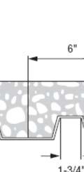
7 ESR-72 Most Widely Accepted and Trusted Page 4 of 6 DESCRIPTION Steel Fastener w/plastic Tophat Washer Steel Fastener w/metal Tophat Washer TABLE ALLOWABLE LOADS FOR S DRIVEN INTO STEEL,2 (lbf) SHANK DIAMETER (INCH) / 8 / 6 STEEL THICKNESS (INCH) / 4 Tension Shear Tension Shear Tension Shear Tension Shear Tension Shear Tension Shear X-S THP X-S6P8TH Gas Fastener X-EGN Gas Fastener X-EGN Gas Fastener X-GHP For SI: inch = 2.4 mm, ksi = 6.89 MPa, lbf = 4.4 N. Unless otherwise noted, fasteners must be driven to where the point of the fastener penetrates through the steel base material. 2 Unless otherwise noted, steel base material must have minimum yield and tensile strengths (F y and F u ) equal to 6 ksi and 8 ksi, respectively. Steel base material must have minimum yield and tensile strengths (F y and F u ) equal to 0 ksi and 6 ksi, respectively. 4 For steel base-material thickness greater than or equal to / 8 inch, fastener point penetration through the steel is not necessary, provided a minimum embedment of 0.20 inch is achieved. / 8 / 2 / 4 TABLE 2 ALLOWABLE LOADS FOR S DRIVEN INTO NORMAL-WEIGHT CONCRETE,2 (lbf) DESCRIPTION DIAMETER (INCH) Gas Fastener X-GN 0.8 Gas Fastener X-GHP 0.8 EMBEDMENT (INCHES) CONCRETE COMPRESSIVE STRENGTH 2,000 psi 4,000 psi 6,000 psi Tension Shear Tension Shear Tension Shear / / / Standard Fastener X-C 0.8 Standard Fastener w/metal Tophat Washer X-C22 P8TH 0.8 For SI: inch = 2.4 mm, psi = kpa, pound = 4.4 N / / Fasteners must not be driven until the concrete has reached the designated minimum compressive strength. 2 Concrete thickness must be a minimum of times the embedment depth of the fastener. TABLE ALLOWABLE LOADS FOR S INSTALLED IN MINIMUM,000 psi LIGHTWEIGHT CONCRETE,2 (lbf) DESCRIPTION DIAMETER (INCH) Gas Fastener X-GN 0.8 Gas Fastener X-GHP 0.8 EMBEDMENT (INCHES) INSTALLED INTO CONCRETE Tension Shear INSTALLED THROUGH METAL DECK INTO CONCRETE Upper Flute Tension Lower Flute Upper Flute Shear Lower Flute / / / Standard Fastener X-C Standard Fastener w/metal Tophat Washer X-C22P8TH X-C20 THP For SI: inch = 2.4 mm, psi = kpa, lbf = 4.4 N / / / Fasteners must not be driven until the concrete has reached the designated minimum compressive strength. 2 Unless otherwise noted, concrete thickness must be a minimum of times the embedment depth of the fastener. Steel deck panel profile must be -inch-deep composite floor deck panel with minimum No. 20 gage (0.09-inch-thick base steel thickness) and minimum yield strength of 8 ksi. Sand-lightweight concrete fill above top of metal deck panel profiles must be 2 / 2 inches thick for the / 8 and / 4 -inch fastener embedment and / 4 inches for the -inch fastener embedment. 4 The steel deck panel profile must be -inch-deep composite floor deck panel, mils thick with a inch base-metal thickness and minimum yield strength of ksi. Lower and upper flute width must be a minimum of 4 / 2 inches. Sand-lightweight concrete fill depth above top of metal deck panel must be a minimum of / 4 inches. See Figure for nominal flute dimensions, fastener locations, and load orientations. See notes and 4 above for minimum concrete thickness.
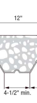
8 ESR-72 Most Widely Accepted and Trusted Page of 6 DESCRIPTION TABLE 4 ALLOWABLE LOADS FOR S INSTALLED IN MINIMUM,000 psi SAND-LIGHTWEIGHT CONCRETE OVER / 2 -INCH-DEEP, B-DECK STEEL PANEL,2 (lbf) DIAMETER (INCH) Gas Fastener X-GN 0.8 Gas Fastener X-GHP 0.8 Standard Fastener X-C Standard Fastener w/metal Tophat Washer X-C22P8TH For SI: inch = 2.4 mm, psi = kpa, lbf = 4.4 N. EMBEDMENT (INCHES) LOCATION Installed Through Metal Deck Into Concrete Tension Shear Upper Flute Lower Flute Upper Flute Lower Flute / / / / Fasteners must not be driven until the concrete has reached the designated minimum compressive strength. 2 Unless otherwise noted, concrete thickness must be a minimum of times the embedment depth of the fastener. Steel deck panel profile must be / 2 -inch-deep, B-type deck panel, minimum No. 20 gage (0.09-inch-thick base steel thickness) and minimum yield strength of 8 ksi. Sand-lightweight concrete fill above top of metal deck panel profiles must be 2 / 2 inches thick for the / 4 -inch fastener embedment and / 4 inches for the -inch fastener embedment. 4 The steel deck panel profiles are / 2 -inch-deep, B-type deck panel with a thickness of mils (0.029-inch-thick steel) and minimum yield strength of 8 ksi. Fasteners may be installed through steel deck panels having either normal and inverted orientations with minimum lower flute widths of / 4 and / 2 inches, respectively. Fasteners must be placed at centerline of deck panel flutes. Figures 2 and describe additional flute dimensions, fastener locations and load orientations for both deck panel profiles. See Figures 2 and for nominal flute dimensions, fastener locations, and load orientations. See note and 4 above for minimum concrete thickness. DESCRIPTION TABLE ALLOWABLE LOADS FOR S INSTALLED IN CONCRETE MASONRY UNITS (CMU),2,7 (lbf) SHANK DIAMETER Gas Fastener X-GN 0.8 Standard Fastener X-C 0.8 For SI: lbf = 4.4 N, inch = 2.4 mm. MINIMUM EMBEDMENT HOLLOW CMU GROUT FILLED CMU Face Shell Mortar Joint Face Shell Mortar Joint Top of Grouted Cell Tension Shear 6 Tension Shear 4 Tension Shear 6 Tension Shear 4 Tension Shear 6 / / See Section.2. for CMU, mortar and grout requirements. 2 No more than one fastener may be installed in an individual masonry unit cell. Fastener can be located anywhere on the face shell. 4 Shear direction can be horizontal or vertical (bed joint or head joint) along the CMU wall plane. Fastener located in center of grouted cell installed vertically. 6 Shear can be in any direction. 7 Fasteners must be installed a minimum of 8 inches from the end of the wall. Multiple fasteners in a bed joint must be spaced a minimum of 8 inches.


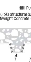
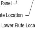
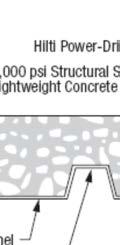
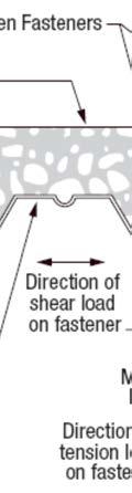

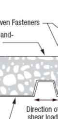
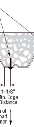
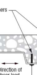
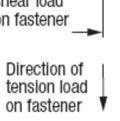
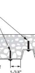
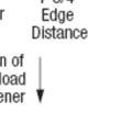
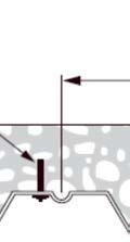
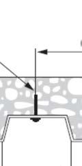
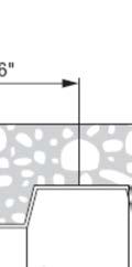
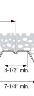
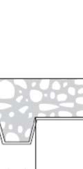
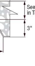
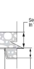
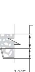
9 ESR-72 Most Widely Accepted and Trusted Page 6 of 6 FIGURE HILTI INSTALLATION LOCATION IN -INCH-DEEP COMPOSITE FLOOR DECK PANEL FIGURE 2 HILTI INSTALLATION LOCATION IN / 2 -INCH-DEEP COMPOSITE FLOOR DECK PANEL FIGURE HILTI LOCATIONS IN / 2 -INCH-DEEP COMPOSITE FLOOR DECK PANEL, INVERTED DECK PANEL PROFILE ORIENTATION
10 ICC-ES Evaluation Report (800) (62) ESR-72 FBC Supplement Reissued August, 20 This report is subject to renewal September, 20. A Subsidiary of the International Code Council DIVISION: CONCRETE Section: 0 00 Concrete Accessories Section: Concrete Anchors DIVISION: MASONRY Section: Masonry Anchors DIVISION: METALS Section: Metal Fastenings DIVISION: FINISHES Section: Fasteners REPORT HOLDER: HILTI, INC. 400 SOUTH 22 ND EAST AVENUE TULSA, OKLAHOMA 7446 (800) HNATechnicalServices@hilti.com EVALUATION SUBJECT: HILTI LOW-VELOCITY POWER-DRIVEN S.0 EVALUATION SCOPE Compliance with the following codes: 2007 Florida Building Code Building 2007 Florida Building Code Residential Property Evaluated: Structural 2.0 PURPOSE OF THIS SUPPLEMENT This supplement is issued to indicate that the Low-velocity Power-Driven Fasteners, described in Sections 2.0 through 7.0 of the master report ESR-72, comply with the 2007 Florida Building Code Building and the 2007 Florida Building Code Residential, when designed and installed in accordance with the master evaluation report. For products falling under Florida Rule 9B-72, verification that the report holder s quality assurance program is audited by a quality assurance entity approved by the Florida Building Commission for the type of inspections being conducted is the responsibility of an approved validation entity (or the code official when the report holder does not possess an approval by the Commission). This supplement expires concurrently with the master report reissued August, 20. ICC-ES Evaluation Reports are not to be construed as representing aesthetics or any other attributes not specifically addressed, nor are they to be construed as an endorsement of the subject of the report or a recommendation for its use. There is no warranty by ICC Evaluation Service, LLC, express or implied, as to any finding or other matter in this report, or as to any product covered by the report. Copyright 20 Page of 000