USER S MANUAL HAKI PUBLIC ACCESS STAIR
|
|
|
- Arabella O’Connor’
- 5 years ago
- Views:
Transcription

1 USER S MANUAL HAKI PUBLIC ACCESS STAIR HAKI AB 2018
2 Important information HAKI s product liability and user s manuals apply only to scaffolds that are entirely composed of components that have been made and supplied by HAKI. HAKI s scaffold systems must not be erected using components of makes other than HAKI or be connected to scaffolds of makes other than HAKI. In such cases, a special study of load-bearing capacity must be carried out. However, HAKI has no objection to the customary addition of scaffold tubes and approved couplers to the scaffold. Adding components from different suppliers may invalidate the insurance cover. This user s manual is based on a minimum of 2 competent erectors. This user s manual is to be used in conjunction with HAKI training courses. A user s manual should be provided to the user together with the scaffolding. HAKI reserves the right to make technical modifications on a continual basis. The latest versions of HAKI user s manuals can be downloaded from our website, For scaffold structures that are not covered by this user s manual, please contact HAKI s technical department. HAKI colour code Horizontals and diagonals are marked with their nominal sizes (bay sizes) and a colour code. The marking is a useful means of identification when erecting and handling the scaffold material Forces and dimensions 1000 N = 1 kn ~ 100 kg 10 N ~ 1 kg All measurements in mm Copyright HAKI AB, 2018 The reproduction of text and pictures/illustrations without HAKI s permission is prohibited. 2
3 HAKI Public Access Stair BASIC INFORMATION Public Access Stairs are designed for loadings up to 7.5 kn/m² and are suitable for public use in line with national standards. Public Access Stair complies with requirements of UK standard The Building Regulations 2000 Protection from falling, collision and impact: The requirement K1. Stairs, ladders and ramps: shall so be designed, constructed and installed as to be safe for people moving between different levels in or about the building. General The HAKI Public Access Stair incorporates the use of many HAKI Universal system components including the base jacks, standards, diagonal braces, ledgers and landings. The stair stringers and handrails are specially designed for use on a Public Access Stair. HAKI PAS are erected in bay widths of 1250mm, 1655mm or 1964mm and lengths of 1655mm or 2500mm. Lift heights can be 500, 1000 or 1500mm. Single Ledger Beams or Ledger Beams can be used as both Transoms or Ledgers. The stair tower can be erected as a free standing entity or to be connected to a scaffold. Marking All components, with the exception of locking catches, locking pins etc, come permanently marked with the HAKI logo and the last two figures of the year of manufacture ( S18). All load bearing components are marked for full traceability. IMPORTANT ENGAGE LOCKING CATCHES AS EACH COMPONENT IS FIXED 3

4 BASIC INFORMATION Standard Landing Handrail Diagonal Brace Handrail PAS Single Ledger Cover O Single Ledger Entrance Handrail Stringer AL plank Base jack Single Ledger Entrance Step 4


5 BASIC INFORMATION Standard Landing Handrail Chequer Plate Top Tread Chequer Plate Tread Diagonal Brace Handrail Chequer Plate Mating Tread Single Ledger Entrance Handrail Stringer Chequer Plate Tread Base jack Single Ledger Entrance Step Chequer Plate Decks 5
6 LIST OF COMPONENTS Name Code/Data Item No. Weight(kg) Base Jack BS Adjustable mm Standard S Standard joint with spigot Pockets at same level Ø48 mm Standard SC Standard joint without spigot Pockets at same level Ø 48 mm Tripod With pockets on one standard Pockets at same level Ø 8 mm Adapter Tripod Adapter tripod 60 Base jack BS Ledger Beam With spring locking catch Ø 34 mm
7 LIST OF COMPONENTS Name Code/Data Item No. Weight(kg) Single Ledger With spring lacking catch Ø 48 mm Spacer PAS Single Ledger Cover With spring lacking catch Ø 48 mm Detail O S 1250 O 1250 S 1655 O 1655 S 1964 O 1964 S Entrance Step 3-step Stringer 1655 x x Entrance Handrail 3-step Handrail Adiustable in height 1655 x x lntermediate Handrail 1655 x

8 LIST OF COMPONENTS Name Code/Data Item No. Weight(kg) Landing Handrail Tripod Handrail Adjustable in height Diagonal Brace With wedge junctions Ø 48 mm 1250 L= L= L= L= AL plank 770x320x x320x x295x x200x x320x x295x x200x x320x x295x x200x
9 LIST OF COMPONENTS Name Code/Data Item No. Weight(kg) Chequer Plate Top Tread Compatible with both PAS and HBS Chequer Plate Mating Tread 1655x x Chequer Plate Tread 1655x x Chequer Plate Deck Compatible with both PAS and HBS Erection Accessories 1250x x x x x x Name Code/Data Item No. Weight(kg Grating AL 1655x Decking unit 1655x x Decking unit with hatch 1655x x Guardrail frame Erecting tool Advanced guardrail tool For other accessories, see HAKI Component List. 9
10 Information on safety when erecting and dismantling 1. Carry out local risk assessment and method statement. 2. Make sure that all lifting equipment to be used, e.g chain hoists, lifting ropes, pulley blocks, etc., has been thoroughly tested and approved by an authorised person in accordance with local regulations. 3. Check that tools and protective equipment are available at the worksite. 4. Wear appropriate personal safety equipment at all times, e.g. safety harnesses, proper independence lifelines with suitable fixings, etc. 5. When erecting and dismantling a scaffold, robust temporary decking must be used as temporary platform for the scaffolders. 6. Always make sure that the safety locking devices that prevent a platform lifting off have been activated once a platform has been installed. 7. Never climb up a scaffold from the outside. Always use the stairs, ladders or climbing frames that are designed to provide access to the upper decks from the inside of the scaffold. 8. If the scaffold is to be used outdoors, erection or dismantling work must be discontinued of the weather conditions are too bad. Make sure that all loose components are properly fixed before leaving the scaffold. 9. Scaffolding work must be carried out by competent operatives under the supervision of a competent person. 10. Lifting equipment must not be attached to a free-standing scaffold without design. 11. Beware of any overhead power lines nearby. 12. Always observe and comply with the regulations issued by the local authorities concerned. 10
11 ERECTION Before erecting the Public stair, check and flatten out the ground. The ground must not be subject to uneven settlement. Its bearing capacity may be improved with the help of sole plates. 1. Set out sole plates, base jacks, standards, horizontals and stair stringers as shown for the first tower Set base jacks under Entrance Step closed (ie minimum height). Place standards onto base jacks Fit the 3 step entrance stair stringers onto the end standards. Adjust the base jack heights to ensure the stair stringers are level and the first step is not too high. Note at top of entrance steps use single ledger with cover if Aluminium Treads are used


12 ERECTION 4. Fit the stair stringer. Note if Aluminuim Treads are used and more stair stringer are going to be added, related single beam will be with a cover plate Fit the entrance handrails into the pockets on the standard and the base jack. Lock the handrail in the higher position to allow treads to be fitted beneath Position the handrails in place. Leave in the open position and do not lock
13 ERECTION 7. Using the Advanced Guardrail tool secure the end guard rail into the standard pockets. Remember to engage locking catches. Repeat to secure the end tower and place decking units and ladder for access Fit stair treads onto the stair stringers Secure the stair tread with the locking catch
14 ERECTION 10. Standing on the end tower, place the stair stringer on the single beam and slide the stair stringer to the other side. Finally place the high end of the stringer into the pocket and lock it In order to safely board out the stair stringers, place a decking unit beneath the stair stringer. Follow Personal Fall Protection Equipment Guidance as shown on page Insert 700 mm guard frames to secure the working platform and meet collective fall protection guidelines
15 ERECTION 13. Fit the handrails to the standards and leave unlocked and in the open position as before Secure the handrails and guard frames to enclose the end tower Deck the stair stringer half way from the lower tower

16 ERECTION 16. Standing on the decking units below fit the remaining treads in place. Secure the stair tread with the locking catch To deck the landing, slide each stair tread under the guard frame and handrails. Once complete remove the decking units below. Fully brace each tower. To continue the stair tower upwards, create another tower and fit the stair stringers as shown previously Basic tower complete. If the requirements are for treads covered with plywood and/ or GRP sheeting, this should be carried out at this stage

17 ERECTION 19.! Once decking is complete all handrails MUST be dropped to their lowest position (locking all treads in place). Then all handrails must be fully secured by tightening the screw nuts at each end of the handrails. When stair tower complete, unlock internal slides, then slide handrail to lock decking in place. Finally lock handrails to internal slides. 19. Dismantling procedure 1/ Dismantle the scaffold from the topmost lift. 2/ Start by raising all handrails into the higher position and lock, this will allow planks to be removed from the working platform below. 3/ Remove planks from the guardrailed working platform below. 4/ Remove all handrails from top lift and stringers. 17


18 ERECTION Using the half landing 1. Ensure the guardrails are in place as a collective fall protection measure. Place the 3 step stair stringer into the pockets of the standards and rest onto the landing Insert handrail. Leave in the open and unlocked position Slide the treads under the handrail and secure with the locking catch

19 ERECTION 4. Once the stair is complete, remember to lock the handrail into place as shown previously
20 Information on safety when dismantling DISMANTLING 1. Do not throw or drop materials to the ground. This may damage the material or cause personal injury. The materials must be lowered down to the ground by means of ropes or slings or passed down by hand. 2. If intermediate ties or tie rod tubes have been installed, they must not be removed until the dismantling process reaches the level in question. 3. Always observe and comply with the regulations published by the local authorities concerned. 4. Dismantlers should always be clipped to a single ledger or ledger beam during dismantling. 5. Reference should also be made to section Information on safety when erecting and dismantling on page 10 in this manual. Instructions for dismantling 1. Dismantle the scaffold from the topmost lift. 2. Take down the topmost decking. 3. Take down the horizontals and diagonals of the topmost lift. 4. Finally remove the standards where possible. 5. Repeat 2-4 to take down the second topmost lift and continue the whole process until the dismantling process reached the scaffold is completely dismantled. 20
21 LOADING CONDITIONS Base jacks The stair tower is erected on base jacks. These are either Ø38 mm or Ø60 mm depending on whether Tripods are used or not. Standards Standards of length 3000 or 2000 mm would normally be incorporated into the tower ensuring that sufficient standard extends above each landing level so that advanced guardrail techniques can be employed. Tripods When leg loads exceeed the permissible value(s) for standards, tripods should be employed. The length 3000 mm should be avoided apart from the base level. Otherwise, tripods of length 2000 mm or smaller should be used. For further information please see the product information sheet for Tripods or contact the HAKI Technical Department. Horizontal members The stair tower is erected using ledger beams and/or single ledgers with either 1000 or 1500 mm between lifts, depending on the stair configuration. Each landing level must be provided with horizontal members on all sides. The bottom lift must always be fitted at the lowest possible level. Handrails All stair flights and landings must be provided with handrails at all outside edges. The handrail height must not be less than 1100 mm. Bracing and tying in The stair tower must be braced using vertical diagonal braces to full height on all faces of each landing tower. The stair tower should be anchored at each standard position horizontally and at a vertical spacing of 4m in height. The first anchor in height must not be fitted more than 4m from ground level. Permissible loads The maximum permissible load on stair flights and landings is 7.5 kn/m 2. 21
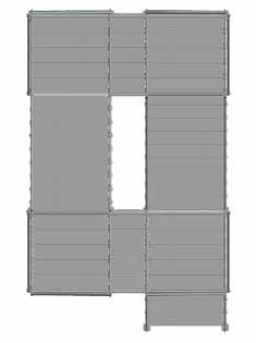
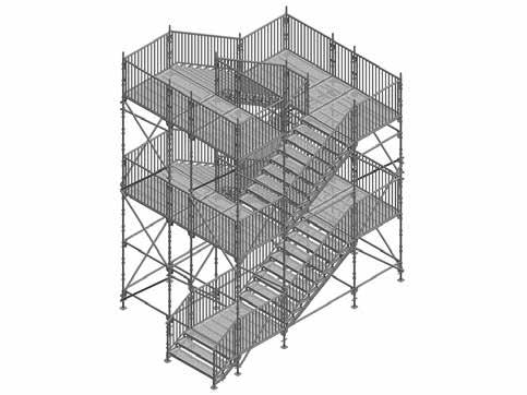
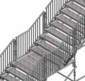
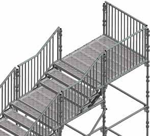
22 EXAMPLE ARRANGEMENTS
23 EXAMPLE ARRANGEMENTS
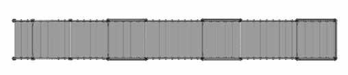
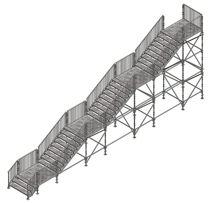
24 ALTERNATIVE ARRANGEMENTS 24

25 Methods of erection when guardrail frame is fitted in advance SAFE SCAFFOLDING Use HAKI s advanced guardrail tool (or the aid of other guardrail fitting devices) to fit guardrail frames prior to the stair flight installation. The standards must be one metre higher than the next lift. For other fitting devices, see HAKI Component List. 25
26 Notes 26
27 SAFETY CHECKLIST 1. Supporting surface checked with regard to load-bearing capacity 2. Distance to wall or similar as short as possible 3. Scaffold aligned correctly horizontally and vertically 4. Components correctly fitted and locked 5. Bracing correctly fitted 6. Anchoring with right number and placing of ties 7. Decking correctly fitted 8. Scaffold erected for correct class of load 27
28 Experience With over 60 years experience to call on, HAKI has gained a leading reputation in its field. With its own R & D and manufacturing facilities, the company now operates throughout Europe and its equipment is in use worldwide. With all products designed and manufactured to ISO 9001:2008, and a comprehensive training and support infrastructure, you can rely on HAKI for support. Training The Company s dedicated Training Centre is equipped with the full range of HAKI products where a comprehensive choice of courses is offered. With the benefit of this training, all users of HAKI products can be assured that the equipment is being employed safely and effectively. Support From computerised estimating facilities to on site assessment and project back up, HAKI is with its customers every step of the way. Working with HAKI means far more than just proven equipment, it means working with people who understand the scaffolding industry. Whatever the project, the company is committed to ensuring every user enjoys the full benefits associated with the use of HAKI - maximising the savings, profitability, and above all, SAFETY. Health and Safety at Work Act, 1974 HAKI equipment is designed to meet the requirements of the above Act, Section 6. It is also the customer s responsibility to comply with the requirements of this Act, particularly to use the equipment in accordance with current codes of practice and in ensuring that components are in good working condition prior to each use. We are able to provide assistance and advice on matters relating to safe and proper use of HAKI equipment. HAKI AB SE Sibbhult, Sweden Tel info@haki.se HAKI INT P000172