One and Two Family Residential Construction. Guidelines & Inspection Checklist
|
|
|
- Shana Conley
- 5 years ago
- Views:
Transcription


1 One and Two Family Residential Construction Guidelines & Inspection Checklist Revised March 21,
2 Based on the 2012 International Residential Code and the 2011 National Electric Code THIS IS A GUIDELINE ONLY IF YOU SHOULD HAVE ANY QUESTIONS PLEASE CALL OUR OFFICE!! DEVELOPMENT DEPARTMENT BUILDING REGULATIONS Office Hours: 8:30-4: W. Mt. Vernon St. PO Box 395 Nixa, MO Phone: Fax: R101.3 Intent. The purpose of this code is to establish minimum requirements to safeguard the public safety, health and general welfare through affordability, structural strength, means of egress facilities, stability, sanitation, light and ventilation, energy conservation and safety to life and property from fire and other hazards attributed to the built environment and to provide safety to fire fighters and emergency responders during emergency operations. 2
3 TABLE OF CONTENTS Site Planning Required Inspections Setbacks Zero Lot Line Duplexes Footing & Stemwalls Minimum Floor Elevation Piers & Columns Brick Ledge Waterproofing & Damp Proofing Crawl Space Concrete Floor (0n ground) Framing Floors Walls Wall Sheathing Ceiling & Roof Attic Ventilation Attic Access Purlins Wood Trusses Bracing Alterations to Trusses Truss Uplift Resistance Ceiling Height FireBlocking Means of Egress Emergency Escape & Rescue Openings Glazing Electric Temporary Power Permanent Power & Electric Ditch Service Size and Rating Panel Boards Branch Circuits Receptacle Outlets Smoke & Carbon Monoxide Alarms GFIC & AFCI Protection Plumbing Water Supply
4 TABLE OF CONTENTS Fixtures Drainage & Vent Systems Sumps & Injectors Drilling & Notching Gas Piping Systems Sewer Lateral Mechanical Duct Installation Water Heaters Fireplaces Final Inspection Checklist Construction Sediment & Erosion Control Guidelines
5 Site planning for One & Two Family Homes CONTRACTOR/BUILDER RESPONSIBILITIES All houses shall have the address posted on property during construction. Permanent address must be posted before occupancy. All construction sites shall have a portable rest room for construction workers. The builder is responsible for hooking up the correct water line and meter to the correct building on multifamily residences. Builders who need water during construction shall hook up a frost free hydrant on the outside base of the water meter. No kind of apparatus is allowed inside meter box. Excess mud, dirt, and rock on the street shall be cleaned up by contractor. Storm water drainage fences & protection. The builder is responsible for making sure landscaper does not cover water meters with dirt or sod during final grade. All materials that are used must be approved by U.L. or equal agency. The contractor is responsible for the maintenance, repair, and/or replacement of the water meter, water meter pit and lid, electric vaults, and related equipment, at no expense to the City of Nixa. This informational handout is based on the 2012 IRC one and two family dwelling code, the 2011 National Electric Code and other Nixa City Ordinances. The purpose of this handout is to better present and clarify code interpretation and enforcement for construction of a one or two family dwelling; however, it by no means attempts to address every code item. The Building Department s mission is to work with the Contractors and the public so that the consumer may purchase a quality home that meets or exceeds the requirements of the code in the City of Nixa. 5
6 REQUIRED INSPECTIONS For on-site construction, the building department inspectors, upon notification from the permit holder or his agent, will make all necessary inspections and will either approve that portion of the construction as completed or disapprove that same portion, state why on an inspection slip and post the inspection slip in a conspicuous place. Inspections consist of but are not limited to the following items: Footing: Commonly made after areas are excavated, forms erected and required steel is in place prior to the placing of concrete. Foundation (Stem Wall): Commonly made after footing concrete has been placed, forms erected, and required steel is in place prior to placing of concrete; or during and upon completion of laying concrete block foundation. Temporary Electric: Usually at footing-foundation stage prior to framing. In-ground Plumbing: Inspection required before any concealment, before fixtures are set and prior to framing inspection. Sheathing: Before house wrap & windows Rough Ins: Rough In inspections include the following: Framing: Required after the roof, all framing, fire stopping, draft stopping and bracing are in place. Electric: Inspection required before any concealment Plumbing Mechanical: Inspection required before any concealment, before fixtures are set Gas Test Draft Stop Sewer Inspection: Before sewer connection. Electric Ditch: Permanent Electric: After all rough-in inspections are approved, usually at drywall stage. Final Inspection: Commonly made after building is complete and yard and driveway are completed. OCCUPANCY: No building shall be occupied until a final inspection is approved! If occupancy occurs a fine will be assessed and a ticket will be issued and you will have to appear in front of the City Judge. City Ordinance ; IRC
 SETBACKS: This term refers to zoning regulations regarding the location of a building on the lot or")
 25 ft. 5 ft. 20 ft. 12 ft.")
7 ONE & TWO FAMILY DWELLING SETBACKS Single family (corner lot) Each side yard is 5 feet unless corner lot TWO-FAMILY (Duplex/Townhouse) SETBACKS: This term refers to zoning regulations regarding the location of a building on the lot or parcel of land. The setbacks vary with the use of the building and the zoning district. The setback requirements are: Front Side Back Street Side Single Family (R-1) 25 ft. 5 ft. 20 ft. 12 ft. Duplex & Townhouse (R-4 & R-5) 20 ft. 6 ft. 15 ft. 12 ft. 7
8 ZERO LOT LINE DWELLINGS Townhouse A single-family dwelling unit constructed in a group of three or more attached units in which each unit extends from foundation to roof and with a yard or public way on at least two sides. Common Wall A common 2-hour fire-resistive wall is permitted for townhouses if such walls do not contain plumbing or mechanical equipment, ducts or vents in the cavity of the common wall. Electrical installations are limited to electrical wire installed in raceways and electrical outlet boxes. R302.2 Continuity The common wall for townhouses shall be continuous from the foundation to the underside of the roof sheathing, deck or slab and shall extend the full length of the common wall. R Materials The wall separating the dwelling may be of masonry or wood construction with 2 layers of 5/8" type X fire resistant gypsum board applied on both sides of separating wall. No combustible material may extend through the fire wall. The fire wall must extend out to the back of the fascia board when there is an overhang. Parapets Parapets shall be provided for townhouses when roof surfaces adjacent to the wall are at the same elevation. The parapet shall extend not less than 30" above the roof surfaces. R Exceptions A parapet is not required when the roof decking is of noncombustible material or approved fire-retardant treated wood for a distance of 4' on each side of the wall. DUPLEXES Dwelling units in two-family dwellings are required to be separated from each other by wall and/or floor assemblies of not less than 1-hour fire-resistive rating (2 layers of 5/8 type X sheet rock. Fire-resistive, floor/ceiling and wall assemblies shall extend to and be tight against the exterior wall, and wall assemblies shall extend to the underside of the roof sheathing. R302.2 Sound Insulation Wall and floor assemblies separating dwelling units shall provide airborne and impact sound insulation for floor/ceiling assemblies. These assemblies shall meet a sound transmission class of 45. 8

9 Footing and Stemwalls Footing Inspection Requirements R401 Building permit has been posted on-site. R105.7 The lot and street number has been posted. Building drawings are on site and available to the inspector All property pins have been located. The minimum dimensions for footings are based on loading and assumed allowable soil pressure of 2000 pounds per square foot. Footing widths or the depth of footings below natural grade may have to be increased if the supporting soil is of a type not having an allowable bearing pressure of at least 2000 pounds per square foot. R Minimum requirements for footings R401.2 Concrete can only be placed on frost-free surfaces Concrete footing shall be protected from freezing during depositing and for a period of not less than five days thereafter. Concrete in footings shall have a compressive strength of not less than 2500 lbs. per square inch in 28 days. R402.2 Depth. Footings are to be poured on a solid bearing surface. All exterior footing shall be placed at least 12 inches below the undisturbed ground surface and minimum of 18 inches below finish grade. R Footings shall be at least 6 inches in thickness R403.1(1) Width TABLE R403.1 MINIMUM WIDTH OF CONCRETE, PRECAST OR MASONRY FOOTINGS (inches) a All loose dirt and debris have been removed from interior of the footing. Footing soil is free of vegetation roots branches. The footing is clear of water. Concrete 9
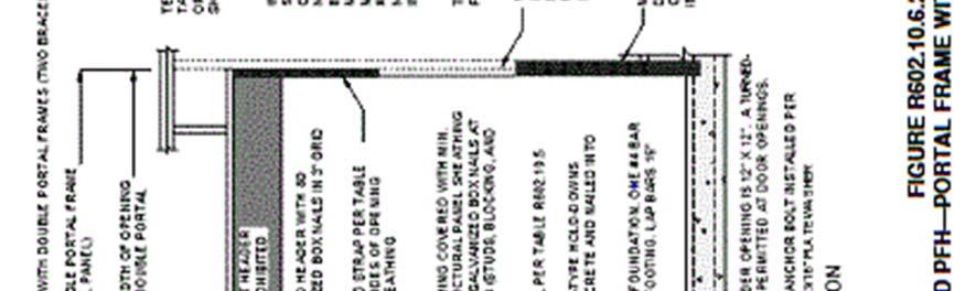
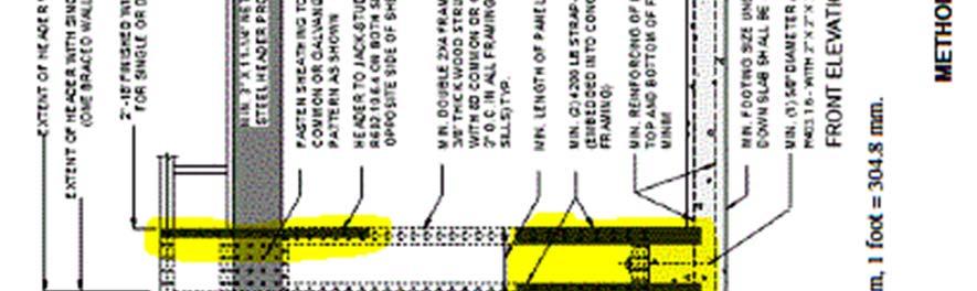
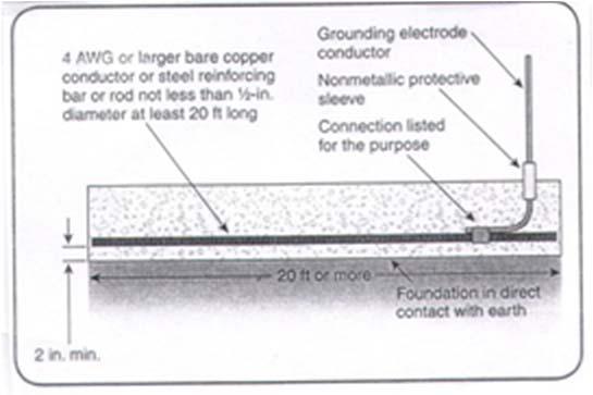
10 Slope. The top surface of footing shall be level. The bottom surface of footing shall not have a slope exceeding one vertical in 10 units horizontal (10% slope) Concrete encased electrode (uffer ground) One or more bare steel re-enforcing rods not less than ½ inch in diameter installed in a continuous 20 foot length. E The rebar re-enforcing has been installed and sets on steel high chairs (no bricks or stones allowed) FOUNDATION R404 Concrete and masonry foundation walls shall extend above the finished grade adjacent to the foundation at all points a minimum of 4 inches where masonry veneer is used and a minimum of 6 inches elsewhere. R Stem walls are to be a minimum of 6 inches wide for on (1) story Foundations with stem walls shall have installed a minimum of on #4 bar within 12 inches of the top of the wall and on #4 bar located 3 inches to 4 inches from the bottom of the footing. R Stem wall height should be a minimum of on (1) foot above street curb, depending on grade of lot Foundation shall have 1/2 inch bolts at six (6) feet on center not more than 12 inches from each corner and seven (7) inches into concrete Portal frame with hold-downs. R Method PFH minimum width of narrow wall single-story are minimum of 16 inches and two-story are minimum 24 inches in wide. Concrete 10

11 11 Concrete
12 Minimum Floor Elevation for Storm water Finished Floor Elevation Verification Policy To ensure proper placement of a structure, all lots with a minimum finished floor elevation identified on the recorded Final Plat shall require the submittal of a finished floor elevation certificate upon completion of the basement finished floor and/or garage finished floor and prior to framing of the structure. A surveyor registered in the State of Missouri shall conduct the elevation certification. Results of the survey shall be submitted, stamped, and sealed to the Development department; verifying compliance with the finished floor elevation for the lot on the City s Certification Form. Piers and Columns Piers and columns are vertical members usually made of concrete, brick, block, steel, or wood and are used to support the floor system. Piers and columns may be used to support the complete structure or they may be used in conjunction with the foundation wall and provide intermediate support between riders and beams. The unsupported height of columns shall not exceed ten (10) times their least dimension. Block or hollow masonry unit columns are required to have the cells filled with concrete when their unsupported height exceeds four times their least dimension Hollow columns shall be capped with four (4) inches thick solid masonry Pier column to be at least eight (8) inches thick. Concrete columns shall be doweled to the pier with 1/2 inch rebar. Columns in basements shall be of treated wood, minimum 4X4 or steel posts not less than three (3) inches in diameter Shims for floor joist or girders shall be of hardwood or steel plates. Shim width shall not be less than girder width. Brick Ledge Exterior Veneer supported by foundation, wood or cold-formed steel construction The brick ledge can be formed in the foundation wall or by concrete masonry units bearing on the footing, head and bed joints are required. R607.2 Plywood under brick is required to be covered with felt or sealed Surface drainage shall be diverted to a storm sewer conveyance or other approved point of collection that does not create a hazard. Lots shall be graded to drain surface water away from foundation walls. The grade shall fall a minimum of 6 inches within the first 10 feet. R401.3 Concrete 12

13 Foundation Waterproofing and Damp Proofing R406.1 Concrete and masonry foundation damp proofing. Except where required by Section R406.2 to be waterproofed, foundation walls that retain earth and enclose interior spaces and floors below grade shall be damp proofed from the top of the footing to the finished grade. Masonry walls shall have not less than 3/8 inch Portland cement parging applied to the exterior of the wall. The parging shall be damp proofed in accordance with one of the following: 1. Bituminous coating 2. Three pounds per square yard of acrylic modified cement. 3. 1/8 coat of surface-bonding cement complying with ASTM C Any material permitted for waterproofing in Section R Other approved methods or materials. 6. A 6-mil-thick (0.15 mm) polyethylene vapor retarder shall be applied over the porous layer with the basement floor constructed over the polyethylene. R Concrete 13
14 Crawl Space Ventilation opening is 1 square foot for each 150 square feet of crawl space Openings shall be within 3 feet of each corner of the building Minimum access hole required is 18 inches x24 inches Minimum heights of crawl space to bottom of floor joist is 18 inches or wood girders when closer than 12 inches to exposed ground Concrete Floor (on ground) R506 GENERAL: Concrete slab on ground loors shall be designed and constructed in accordance with the provisions of this section or ACI 332. Floors shall be a minimum 3.5 thick R506.1 The area within the foundation walls shall have all vegetation, top soil and foreign material removed. R506.2 Fill material shall be free of vegetation and foreign material. The fill shall be compacted to assure uniform support of the slab and except where approved, the fill depth shall not exceed 24 inches for clean sand or gravel and 8 inches for earth.r A 6-mil polyethylene or approved vapor retarder with joints lapped not less than 6 inches shall be placed between the concrete floor slab and the base course or the prepared subgrade where no base course exists.r Exception: The vapor retarder may be omitted: 1. From garages, utility buildings, and other unheated accessory structures. 2. For unheated storage rooms, having an area of less than 70 square feet and carports. 3. From driveways, walks, patios and other flatwork not likely to be enclosed and heated at a later date. 4. Where approved by the building official, based on local site conditions. Concrete 14

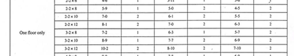
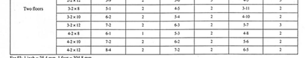
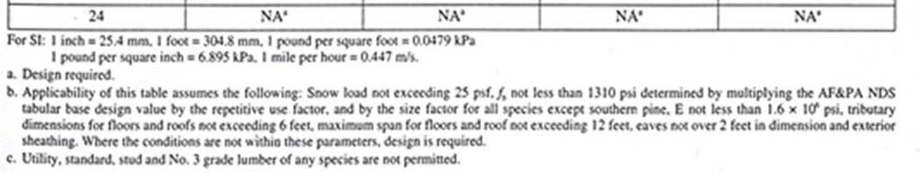
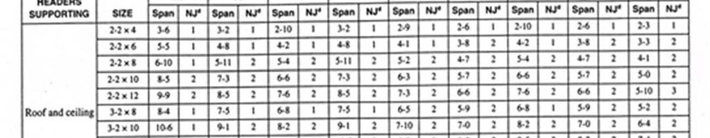
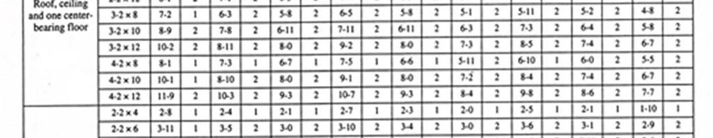
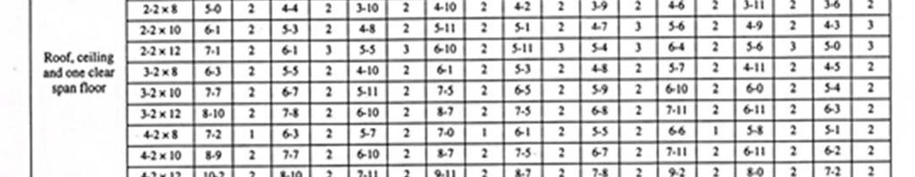
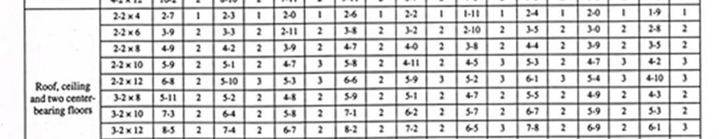
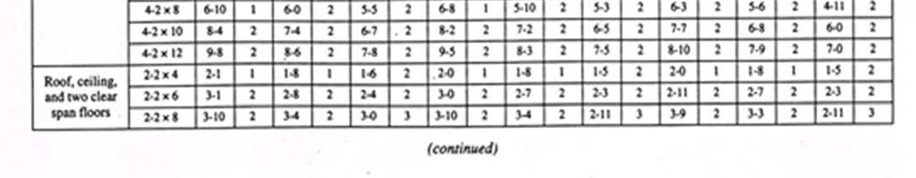
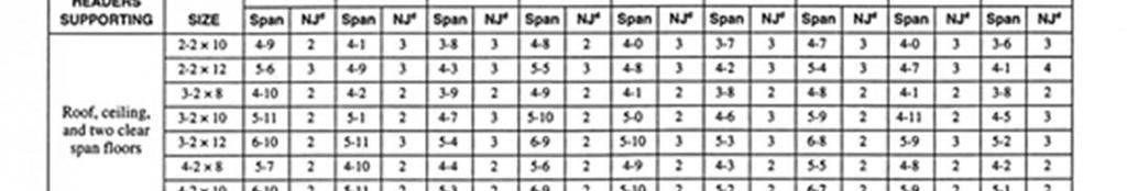
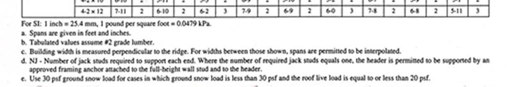
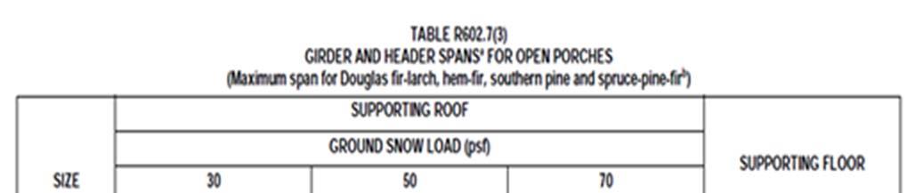
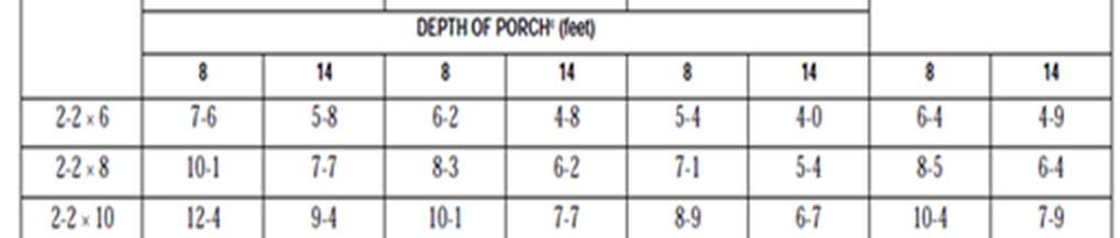
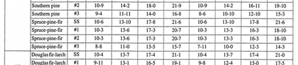
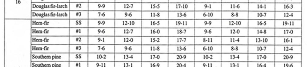
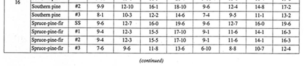
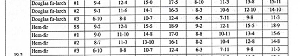
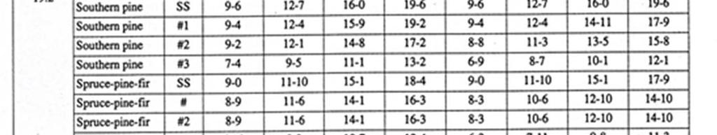
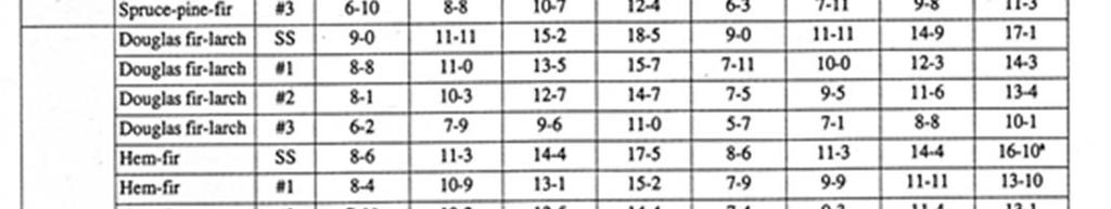
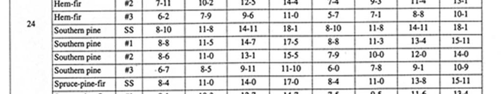
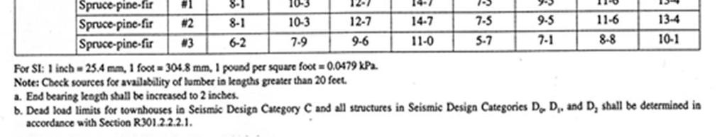
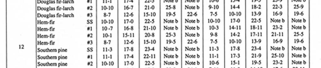
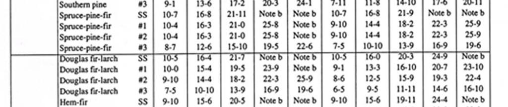
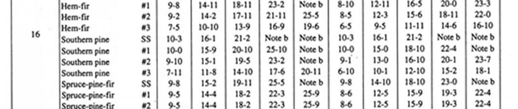
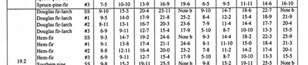
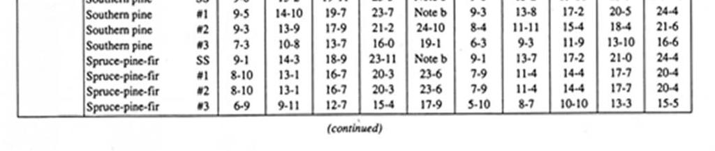
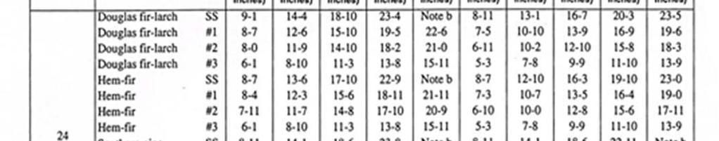
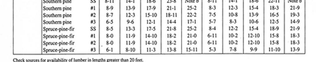
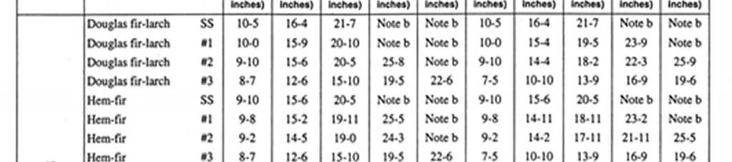
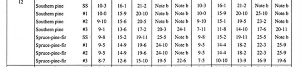
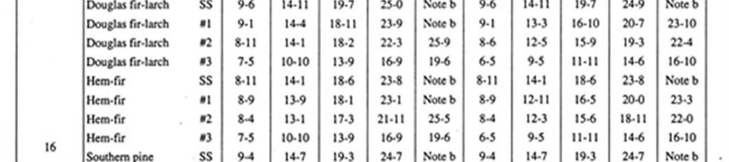
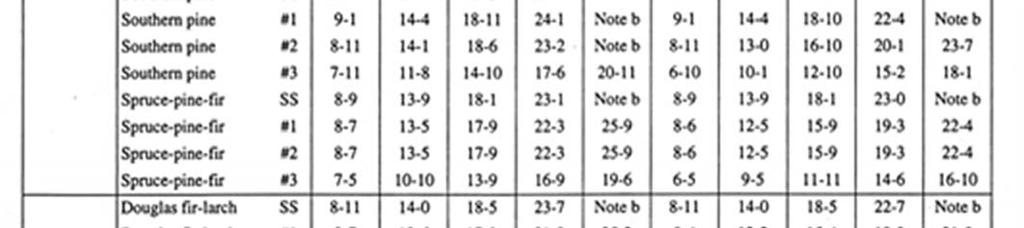
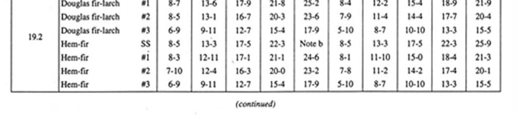
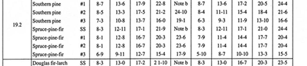
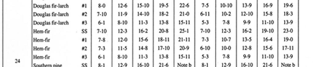
15 Framing Girders Girders are the main horizontal support members upon which the floor system is laid. They are supported by posts, beam pockets, and piers. The arrangement of the girders under the floor system is dependent on the design of the floor system itself and the load it is expected to carry. Some girders are positioned to carry only floor load while others will have to support floors, walls, and roof structures. This can result in girders of various size and spacing. The most common method of laying out girders is to determine the size of the largest girder required and use girders of like size in all locations where they will be needed. This results in a uniform design and makes the job of framing easier. For Girder spans see table 502.5(2) (page 25) Floors R502 All lumber for joists, beams, and girders shall be grade marked by an approved agency and shall be minimum of grade 3# The ends of each joist, beam, or girder shall have not less than 1 1/2 inches bearing on wood or metal and not less than three (3) inches on concrete or masonry Joists attached into the sides of a wood girder shall be supported by approved framing anchors Notches in the top or bottom of joist shall not exceed 1/6th the depth of the joist and cannot be located in the middle 1/3 of the span Holes bored in joists shall not be larger in diameter than 1/3rd the depth of the joist Framing 15
16 Framing 16

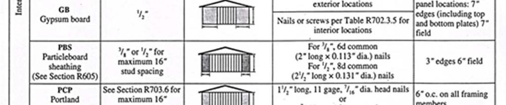
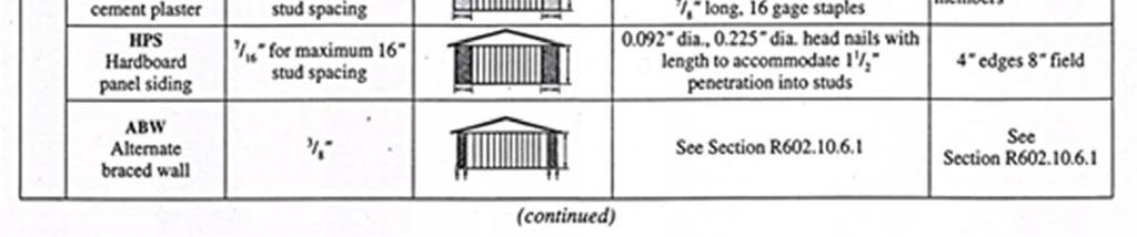
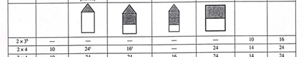
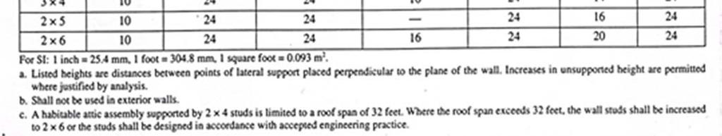
17 Allowable holes in prefabricated I-joist No field cut Minimum distance from Minimum distance from 1 ½ hole may be cut anywhere in web Minimum applies to all holes except Closely grouped round holes are permi ed if the group perimeter Do not cute holes larger Joists under bearing walls shall be doubled. Double joists which are separated to permit installation of piping or vents shall be solid blocked at maximum spacing of 4 on center The clear span of floor joist shall not exceed the values set forth in IRC Tables (page 26) Openings over 4 shall be framed with a header and double trimmer joists Floor trusses shall be designed and installed in accordance with approved engineering practices. Floor trusses shall not be drilled, cut notched, or altered in any manner unless so designed Joists exceeding a nominal 2 by 12 shall be supported laterally by solid blocking, diagonal bridging (wood or metal), or a continuous 1 by 3 strip nailed across the bottom of joists perpendicular to joists at intervals not exceeding Walls Load-bearing dimension lumber for studs and plates and headers shall be grade-marked by an approved agency Studs are to be a minimum grade 3# The size, height, and spacing of studs shall be in accordance with Table R602.3(5) Top Bored hole max diameter 40% of stud Notch must not exceed 25% of Bored holes shall not be located in the same cross 5/8 in mini- If hole is between 40% and 60% of stud depth, then stud must be double and no more than two successive studs Framing 17

18 A stud cannot be cut or notched more than 25% of its width Drilling and notching. Where top plates are cut, drilled, or notched due to piping or duct work more than 50% of its width, the plates shall be reinforced with 24 gauge steel angle or equivalent support Fire stopping shall be provided to cut off all concealed draft openings both horizontal and vertical. In concealed spaces of stud walls and partitions including furred spaces at the celling and floor level. At all soffits, drop ceilings, cove ceilings, in concealed spaces between stair stringers at the top of bottom of the run. Draft stop at openings around vents, pipes, ducts, chimneys, and fireplaces at ceiling and floor level Cripple walls shall be framed of studs not less in size with studding above, with a minimum length of 14 or shall be framed of solid blocking. When exceeding 4, studs will be sized for an additional story Wall Sheathing R Method PFG: Portal frame at garage door openings in Seismic Design Categories A, B, and C. Where supporting a roof or one story and a roof, a Method PFG braced wall panel constructed in accordance with Figure R shall be permitted on either side of garage door openings. Framing 18


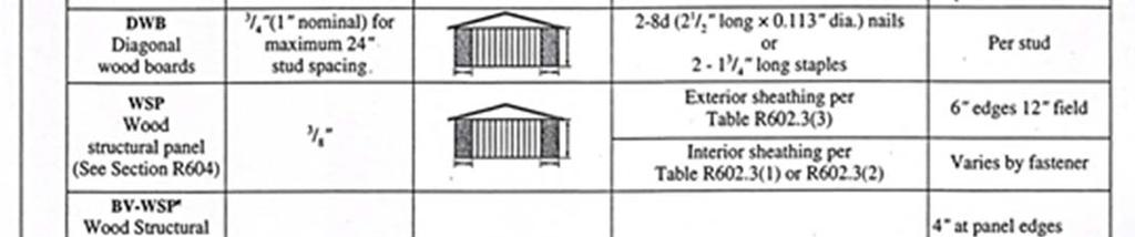
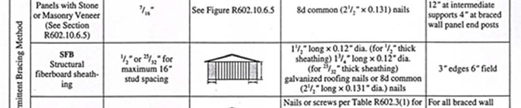
19 Brace wall panels R A braced wall panel shall begin within 10 from each end of a braced wall line as determined in Section R The distance between adjacent edges of braced wall panels along a braced wall line shall be no greater than 20 as shown in Figure R Braced wall lines with a length of 16 or less shall have a minimum of two braced wall panels of any length or one braced wall panel equal to 48 or more. Braced wall lines greater than 16 shall have a minimum of two braced wall panels. Framing 19

20 Framing 20


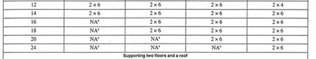
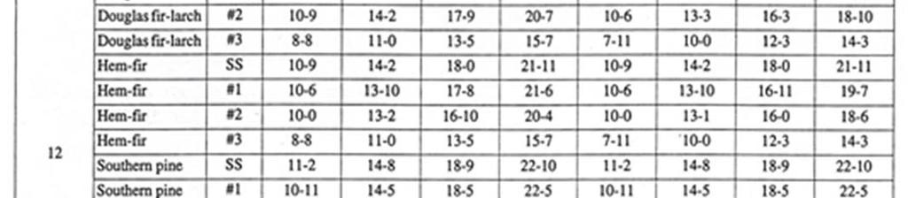
21 Roof and Ceiling: R801 New concepts in ceiling design have brought about new configurations in framing methods and introduced assemblies such as stiff backs, A-frames and trusses to enable the new concepts in ceiling design to be accomplished. Some of these designs are so complex that it is necessary to consult with an engineer to insure structural integrity. All load-bearing dimension lumber for ceiling joists shall be grade marked by an approved agency and shall be a minimum of grade #3. Dimension lumber used for the fabrication of stiff back, A-frames, truss assemblies or other load-bearing assemblies shall be a minimum grade #3. Load-bearing dimension lumber used in roof framing shall be grade marked and shall be a minimum of grade #3. This would include all rafters, purlins, purlin bracing, all hip and valley rafters and ridge boards. Beams used to support raised ceilings shall have solid support to bottom plate. Framing 21
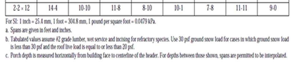
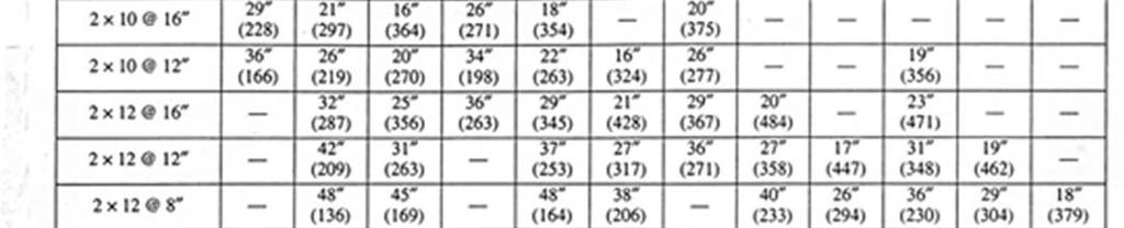
22 Rafters shall be nailed to ceiling joists to form a continuous tie between exterior walls. Where rafters are not parallel, they shall be tied with rafter ties, located as near the plate as practical. Rafter ties shall not be spaced more than 4 on center Bearing: The ends of each rafter or joist shall not have less than 1 1/2 bearing on wood or metal and 3 on concrete Cutting and notching: Notching at the ends of the rafters or ceiling joists shall not exceed 1/4 the depth. Notches in the top or bottom of the joists shall not exceed 1/6 of the depth and shall not be located in the middle 1/3 of the span Bored Holes: Holes bored in rafter and ceiling joists shall not be within 2 of the top and bottom. Their diameter shall not exceed 1/3 the depth of the member. Ridge boards shall be at least 1 nominal thickness and depth shall not be less than the cut at end of the rafter Hips and valley rafters: There shall be a hip or valley rafter not less than 2 nominal thickness and not less in depth than the cut at the end of the rafter at every hip and valley. All hip and valley rafters shall be supported at the ridge by a brace to a bearing partition or be designed to carry and distribute the specific load at that point Rafters and ceiling joists having a depth to thickness ratio exceeding 6 to 1 based on nominal dimensions shall be supported laterally by solid blocking, diagonal bridging (wood or metal) or a continuous 1 by 3 wood strip nailed across the rafters or ceiling joists at intervals not exceeding 8. R Attic Ventilation Enclosed attics and rafter spaces where ceilings are applied directly to the underside of roof rafters shall have cross ventilation for each separate space The net free ventilating area shall not be less than 1 to 150 of the area of the space ventilated except that the area may be 1 to 300, provided at least 50% of the required ventilating area has ventilators located in the upper portion of the space to be ventilated, at least 3' above eave or cornice vents Attic Access A readily accessible attic access framed opening, not less than 22 by 30, shall be provided to any attic area having a clear height of over Purlins The unsupported span of rafters shall not exceed the values set forth in span tables. Intermediate support of long rafters shall be provided with purlins or interior walls. The maximum rafter span is the maximum distance between the exterior or interior wall support and the purlin, or between the ridge member and the purlin or between purlins Purlins shall never be smaller in dimension than the rafters that they support. Purlins shall be braced at no more than 4 on center. Braces for purlins shall not rise to support the purlin of less than 45 degrees above ceiling joists or over 60 degrees Purlin braces exceeding 6 in length are required to be double or teed. Braces are to bear on interior walls or beams designed to carry the load. Do not brace to ceiling joists or stiff backs except where these members are directly over a wall. Wood Trusses Framing Truss design drawings prepared in conformance to Section R shall be provided to the building official and approved prior to installation. Truss design drawings shall be provided with the shipment of trusses delivered to the jobsite. 22
23 Applicability limits. The provisions of this section shall control the design of truss roof framing when snow controls for buildings not greater than 60 in length perpendicular to the joist, rafter or truss span, not greater than 36 in width parallel to the joist, rafter or truss span not more than 3 stories above grade plane in height, and roof slopes not smaller than 3:12 (25 percent slope) or greater than 12:12 (100 percent slope). Truss roof framing constructed in accordance with the provision of this section shall be limited to sites subjected to a maximum design wind speed of 110 miles per hour, exposure A, B, or C and a maximum ground snow load of 70 psf. For consistent loading of all truss types, roof snow load is to be computed as :0.7p R Bracing Trusses shall be braced to prevent rotation and provide lateral stability in accordance with the requirements specified in the construction documents for the building and on the individual truss design drawings. R Alterations to Trusses Truss members shall not be cut, notched, drilled, spliced or otherwise altered in any way without the approval of a registered design professional. Altercations resulting in the addition of load (e.g., HVAC equipment, water heater) that exceeds the design load for the truss shall not be permitted without verification that the truss is capable of supporting such additional loading. R Truss uplift resistance. Trusses shall be attached to supporting wall assemblies by connections capable of resisting uplift forces as specified on the truss design drawings. Uplift forces shall be permitted to be determined as specified by Table R802.11, if applicable, or as determined by accepted engineering practice. R Ceiling Height 305 Minimum Height. Habitable space, hallways, bathrooms, toilet rooms, laundry rooms and portions of basements containing these spaces shall have a ceiling height of not less than Exceptions: For rooms with sloped ceilings, at least 50% of the required floor area of the room must have a ceiling height of at least 7 and not portion of the required floor area may have a ceiling height of less than 5. Bathrooms shall have a minimum ceiling height of 6 8 at the center of the front clearance area for fixtures shall be such that the fixture is capable of being used for its intended purpose. A shower or tub equipped with a showerhead shall have a minimum ceiling height of 6 feet 8 inches above a minimum area 30 inches by 30 inches at the showerhead. Basements. Portions of basements that do not contain habitable space, hallways, bathrooms, toilet rooms, and laundry rooms shall have a ceiling height of not less than 6 feet 8 inches. R Exception: Beams, girders, ducts, or other obstructions may project to within 6 feet 4 inches of the finished floor Framing 23
24 Fireblocking R Fireblocking: In combustible construction, fireblocking shall be provided to cut off all concealed draft openings (both vertical and horizontal) and to form an effective fire barrier between stories, and between a top story and the roof space. Fireblocking shall be provided in wood-frame construction in the following locations: 1. In concealed spaces of stud walls and partitions, including furred spaces and parallel rows of studs or staggered studs, as follows: 1.1. Vertically at the ceiling and floor levels Horizontally at intervals not exceeding 10 feet. 2. At all interconnections between concealed vertical and horizontal spaces such as occur at soffits, drop ceilings and cove ceilings. 3. In concealed spaces between stair stringers at the top and bottom of the run. Enclosed spaces under stairs shall comply with Section R At openings around vents, pipes, ducts, cables and wires at ceiling and floor level, with an approved material to resist the free passage of flame and products of combustion. The material filling this annular space shall not be required to meet the ASTM E 136 requirements. 5. For the fireblocking of chimneys and fireplaces, see Section R Fireblocking of cornices of a two-family dwelling is required at the line of dwelling unit separation. Fireblocking R Fireblocking materials: Except as provided in Section R302.11, Item 4, fireblocking shall consist of the following materials. 1. Two-inch nominal lumber. 2. Two thicknesses of 1-inch nominal lumber with broken lap joints. 3. One thickness of 23/32-inch wood structural panels with joints backed by 23/32-inch wood structural panels. 4. One thickness of 3/4-inch particleboard with joints backed by 3/4-inch particleboard. 5. One-half-inch gypsum board. 6. One-quarter-inch cement-based millboard. 7. Batts or blankets of mineral wool or glass fiber or other approved materials installed in such a manner as to be securely retained in place. 8. Cellulose insulation installed as tested for the specific application. Framing 24
25 25 Framing

26 Framing 26

27 27 Framing

28 Framing 28

29 29 Framing

30 Framing 30

31 31 Framing

32 Framing 32

33 33 Framing
34 Framing 34

35 35 Framing

36 Framing 36

37 37 Framing

38 Framing 38

39 39 Framing

40 Framing 40

41 41 Framing
42 Means of Egress R311 Egress Door. At least one egress door shall be provided for each dwelling unit. The egress door shall be sidehinged, and shall provide a minimum clear width of 32 inches when measured between the face of the door and the stop, with the door open 90 degrees. The minimum clear height of the door opening shall not be less than 78 inches in height measured from the top of the threshold to the bottom of the stop. Other doors shall not be required to comply with these minimum dimensions. Egress doors shall be readily openable from inside the dwelling without the use of a key or special knowledge or effort. R311.2 Floors and landings at exterior doors. There shall be a landing or floor on each side of each exterior door. The width of each landing shall not be less than the door served. Every landing shall have a minimum dimension of 36 inches measured in the direction of travel. Exterior landings shall be permitted to have a slope not to exceed ¼ unit vertical in 12 units horizontal. R311.3 Floor elevations at the required egress doors. Landings or finished floors at the required egress door shall not be more than 1 ½ inches lower than the top of the threshold. Exception. The landing or floor on the exterior side shall not be more than 7 ¾ inches below the top of the threshold provided the door does not swing over the landing or floor. R Floor elevations for other exterior doors. Doors other than the required egress door shall be provided with landings or floors not more than 7 ¾ inches below the top of the threshold. Exception: A landing is not required where a stairway of two or fewer risers is located on the exterior side of the door, provided the door does not swing over the stairway. R Stairways R311.7 Width. Stairways shall not be less than 36 inches in clear width at all points above the permitted handrail height and below the required headroom height. Handrails shall not project more than 4.5 inches on either side of the stairway at and below the handrail heights, including treads and landings, shall not be less than 31 ½ inches where a handrail is installed on one side and 27 inches where handrails are provided on both sides. R Framing Headroom. The minimum headroom in all parts of the stairway shall not be less than 6 feet 8 inches measured vertically from the sloped line adjoining the tread nosing or from the floor surface of the landing or platform on that portion of the stairway. R
43 Vertical Rise. A flight of stairs shall not have a vertical rise larger than 12 feet between floor levels or landings. R Framing 43
44 Walkline. The walkline across winder treads shall be concentric to the curved direction of travel through the turn and located 12 inches from the side where the winders are narrower. The 12 inch dimension shall be measured from the widest point of the clear stair width at the walking surface of the winder. If winders are adjacent within the flight, the point of the widest clear stair width of the adjacent winders shall be used. R Stair treads and risers. Stair treads and risers shall meet the requirements of this section. For the purposes of this section all dimensions and dimensioned surfaces shall be exclusive of carpets, rugs, or runners. R Risers. The maximum riser height shall be 7 ¾ inches. The riser shall be measured vertically between leading edges of the adjacent treads. The greatest riser heights within any flight of stairs shall not exceed the smallest by more than 3/8 inch. Risers shall be vertical or sloped from the underside of the nosing of the tread above at an angle not more than 30 degree from the vertical. Open risers are permitted provided that the opening between treads does not permit the passage of a 4 inch diameter sphere. R Winder treads. Winder treads shall have a minimum tread depth of 10 inches measured between the vertical planes of the foremost projection of adjacent treads at the intersections with the walkline. Winder treads shall have a minimum tread depth of 6 inches at any point within the clear width of the stair. Within any flight of stairs, the largest winder tread depth at the walkline shall not exceed the smallest winder tread by more than 3/8 inch. Consistently shaped winders at the walkine shall be allowed within the same flight of stairs as rectangular treads and do not have to be within 3/8 inch of the rectangular tread depth. R Treads. The minimum tread depth shall be 10 inches. The tread depth shall be measured horizontally between the vertical planes of the foremost projection of adjacent treads and at a right angle to the tread s leading edge. The greatest tread depth within any flight of stairs shall not exceed the smallest by more than 3/8 inch. R Nosings. The radius of curvature at the nosing shall be no greater than 9/16 inch. A nosing not less than ¾ inch but not more than 1¼ inches shall be provided on stairways with solid risers. The greatest nosing projection shall not exceed the smallest nosing projection by more than 3/8 inch between two stories, including the nosing at the level of floors and landings. Beveling of nosings shall not exceed ½ inch. R Framing 44
45 Landings for stairways. There shall be a floor or landing at the top and bottom of each stairway. The minimum width perpendicular to the direction of travel shall be no less than the width of the flight served. Landings of shapes other than square or rectangular shall be permitted provided the depth at the walk line and the total area is not less than that of a quarter circle with a radius equal to the required landing width. Where the stairway has a straight run, the minimum depth in the direction of travel shall be not less than 36 inches. R Exception: A floor or landing is not required at the top of interior flight of stairs, including stairs in an enclosed garage provided a door does not swing over the stairs. Framing 45
46 Handrails. Handrails shall be provided on at least one side of each continuous run of treads or flight with four or more risers. R Height. Handrail height, measured vertically from the sloped plane adjoining the tread nosing, or finish surface of ramp slope, shall be not less than 34 inches and not more than 38 inches. R Continuity. Handrails for stairways shall be continuous for the full length of the flight, from a point directly above the top riser of the flight to a point directly above the lowest riser of the flight. Handrail ends shall be returned or shall terminate in newel posts or safety terminals. Handrails adjacent to a wall shall have a space of not less than inch between the wall and handrails. R Exceptions: Handrails shall be permitted to be interrupted by a newel post at the turn. The use of a volute, turnout, starting easing or starting newel shall be allowed over the lowest tread. Grip-size. All required handrails shall be of one of the following types or provide equivalent graspability. R Type I. Handrails with a circular cross section shall have an outside diameter of at least 1 ¼ inches and not greater than 2 inches. If the handrail is not circular, it shall have a perimeter dimension of at least 4 inches and not greater than inches with a maximum cross section of dimension of inches. Edges shall have a minimum radius of 0.01 inch. Framing Type II. Handrails with a perimeter greater than 6 ¼ inches shall have a graspable finger recess area on both sides of the profile. The finger recess shall begin within a distance of ¾ inch measured vertically from the tallest portion of the profile and achieve a depth of at least 5/16 inch within 7/8 inch below the widest portion of the profile. This required depth shall continue for at least 3/8 inch to a level that is not less than 1 ¾ inches below the tallest portion of the profile. 46


47 The minimum width of the handrail above the recess shall be 1 ¼ inches to a maximum of 2 ¾ inches. Edges shall have a minimum radius of 0.01 inch. Guards. Guards shall be provided in accordance with Sections R Through R R Where Required. Guards shall be located along open-sided walking surfaces, including stairs, ramps, and landings that are located more than 30 inches measured vertically to the floor or grade below at any point within 36 inches horizontally to the edge of the open side. Insect screening shall not be considered as a guard. Framing 47
48 Height. Required guards at open-sided walking surfaces, including stairs, porches, balconies, or landings, shall be not less than 36 inches high measured vertically above the adjacent walking surface, adjacent fixed seating or the line connecting the leading edges of the treads. R312 Exceptions: 1. Guards on the open sides of stairs shall have a height not less than 34 inches measured vertically from a line connecting the leading edges of the treads. 2. Where the top of the guard also serves as a handrail on the open sides of stairs, the top of the guard shall not be less than 34 inches and not more than 38 inches measured vertically from a line connecting the leading edges of the treads. Opening limitations. Required guards shall not have openings from the walking surface to the required guard height which allow passage of a sphere 4 inches in diameter. R Exceptions: 1. The triangular openings at the open side of stair, formed by the riser, tread and bottom rail of a guard, shall not allow passage of a sphere 6 inches in diameter. 2. Guards on the open side of stairs shall not have openings which allow passage of a sphere 4 3/8 inches in diameter. Framing Emergency Escape and Rescue Openings R310 Emergency escape and rescue required. Basements, habitable attics and every sleeping room shall have at least one operable emergency escape and rescue opening. Where basements contain one or more sleeping rooms, emergency egress and rescue openings shall be required in each sleeping room. Where emergency escape and rescue openings are provided they shall have a sill height of not more than 44 inches measured from the finished floor to the bottom of the clear opening. Where a door opening having a threshold below the adjacent ground elevation serves as an emergency escape and rescue opening and is provided with a bulkhead enclosure, the bulkhead enclosure shall comply with Section R The net clear opening dimensions required by this section shall be obtained by the normal operation of the emergency escape and rescue opening from the inside. Emergency escape and rescue openings with a finished sill height below the adjacent ground elevation shall be provided with a window well in accordance with Section R Emergency escape and rescue openings shall open directly into a public way, or to a yard or court that opens to a public way. R310.1 Exception: Basements used only to house mechanical equipment and not exceeding total floor area of 200 square feet. 48
49 Minimum opening area. All emergency escape and rescue openings shall have a minimum net clear opening of 5.7 square feet. R Exception: Grade floor openings shall have a minimum net clear opening of 5 square feet. Minimum opening height. The minimum net clear opening height shall be 24 inches. R Minimum opening width. The minimum net clear opening width shall be 20 inches. R Operational constraints. Emergency escape and rescue openings shall be operational from the inside of the room without the use of keys, tools or special knowledge. R Window wells. The minimum horizontal area of the window well shall be 9 square feet with a minimum horizontal projection and width of 36 inches. The area of the window well shall allow the emergency escape and rescue opening to be fully opened. R310.2 Exception: The ladder or steps required by Section R shall be permitted to encroach a maximum of 6 inches into the required dimensions of the window well. Ladder and steps. Window wells with a vertical depth greater than 44 inches shall be equipped with a permanently affixed ladder or steps usable with the window in the fully open position. Ladders or steps required by this section shall not be required to comply with Sections R311.7 and R Ladders or rungs shall have an inside width of a least 12 inches, shall project at least 3 inches from the wall and shall be spaced not more than 18 inches on center vertically for the full height of the window well. R Framing 49


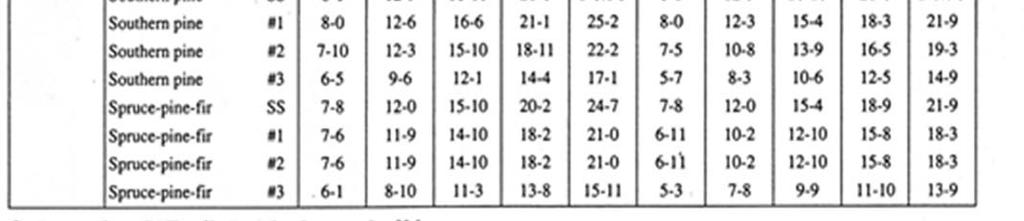
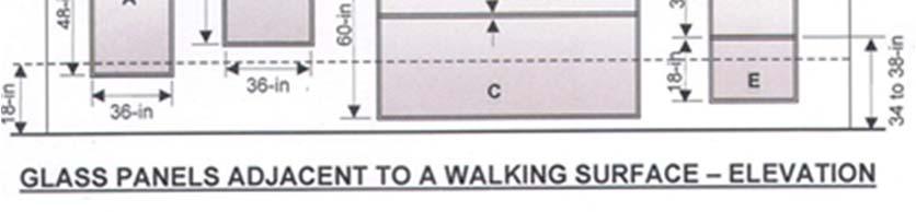
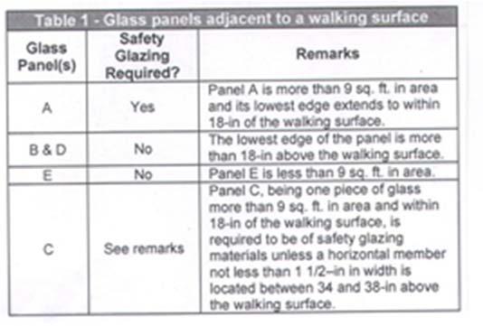
50 Drainage. Window wells shall be designed for proper drainage by connecting to the building s foundation drainage system required by Section R405.1 or by an approved alternative method. R Glazing R308 Identification. Permanent labels and identification marks for glazing installed in hazardous locations is always required. Each unit of tempered glass shall be sandblasted, laser etched embossed or of a type that once applied cannot be removed without being destroyed and be visible when the unit is glazed. R308.1 Hazardous locations. The following are specific hazardous locations where safety glazing is required R308.4: Glazing adjacent doors. Glazing in an individual fixed or operable panel adjacent to a door where the nearest vertical edge of the glazing is within a 24 inch arc of either vertical edge of the door in a closed position and where the bottom exposed edge of the glazing is less than 60 inches above the floor or walking surface shall be considered a hazardous location. R Glazing and wet surfaces. Glazing in walls, enclosures or fences containing or facing hot tubs, spas, whirlpools, saunas, steam rooms, bathtubs, showers and indoor or outdoor swimming pools where the bottom exposed edge of the glazing is less than 60 inches measured vertically above any standing or walking surface shall be considered a hazardous location. This shall apply to single glazing and all panes in multiple glazing. R Glazing in windows. Glazing in an individual fixed or operable panel that meets all of the following conditions shall be considered a hazardous location: Framing 1. The exposed area of an individual pane is larger than 9 square feet; 2. The bottom edge of the glazing is less than 18 inches above the floor; 3. The top edge of the glazing is more than 36 inches above the floor; 4. One or more walking surfaces are within 36 inches, measured horizontally and in a straight line, of the glazing. 50

51 51 Framing

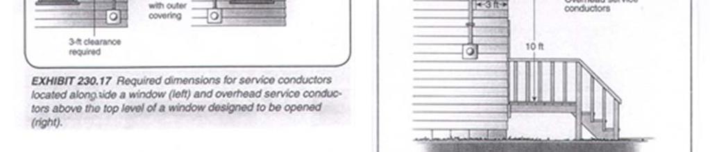
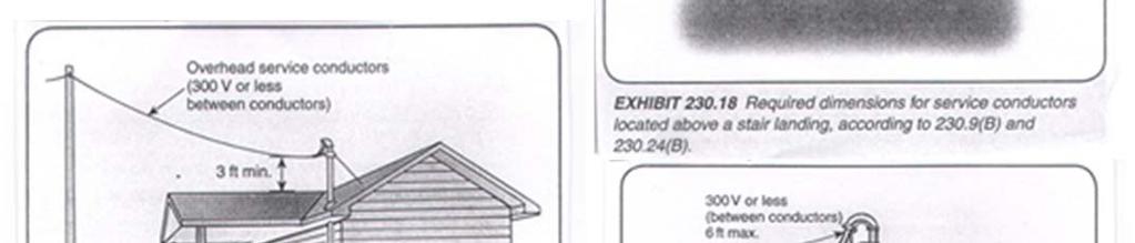
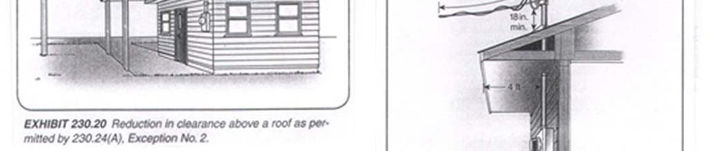
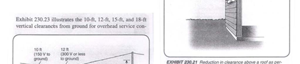
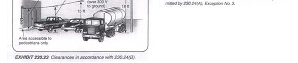
52 Electric Temporary Power Requirements General Specification applying to overhead and underground service. Temporary service requiring the city to extend overhead or underground facilities or install transformers will require additional costs. Check with the electrical superintendent for an estimate of charges and other requirements. Meter base will be mounted on a 4x4 post 4 ½ 5 1/2. Meter post braces should be a minimum of 2x4 lumber with stakes solidly driven into the ground. Do not mount temporary service pole in a location that will conflict with the trenching required for the permanent service conduit. Provide sufficient service conductor to reach the transformer, plus 6 for making connections. Minimum #8 copper ground from meter base to grounding rod. All conductors from the city power source to the meter base and all conductors from the meter base to the panel are to be marked as follows: Neutral legs are to be marked with white tape NEC. GFI protected receptacles. Weather proof enclosure. Service drip clearance requirements are as follows 10 minimum at lowest point of the drip loop, 12 over residential property and driveways, 18 over public streets and parking areas subject to truck traffic. Electric 52

53 53 Electric
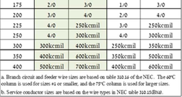
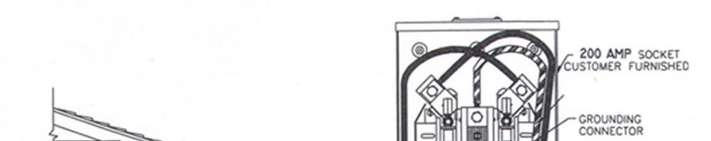
54 Permanent Power and Electric Ditch Requirements Address must be posted before the electric service will be hooked up. Electrical meter base shall be installed on the side of the building toward the front. Contractor is to supply meter base. It must be 200 AMP. A 100amp minimum capacity panel is required to all residential dwellings. Contractor is to supply service entrance conductors and conduit. Meter base height from ground level must be between 5 and 5 ½. Any building with more than one meter shall have address permanently marked on meter base before permanent electric will be hooked up. NEC Roof must be completed. No building will be approved with wet wiring. E Conduit from meter base to ditch, schedule 80 if exposed. Ditch 30 deep. Conduit in ditch must be glued. All conductors from city power source to the meter base and all conductors from meter base to panel are to be marked as follows: Neutral legs are to be marked with white tape NEC Concrete encased electrode consisting of at least 20 of steel reinforcing bars or rods not less than ½ in diameter E Cover shield over panel board. Replacing an existing service all work done will need to meet current codes. Where an uffer ground connection is not accessible 2 ground rods may be used. NEC Residential Service Upgrades Ordinance No All structures for residential purposes, requiring a service upgrade or modification, shall mandate the following electrical system improvements; GFI receptacles in the kitchen(s) and bathroom(s) shall be installed if outlets are in existence at the time of the service upgrade. Approved hard-wired, dual-powered, interconnected smoke detectors shall be installed and located as per the adopted building code. The kitchen shall be provided with a minimum of two grounded small appliance branch circuits. All apparent hazards shall be corrected. If a fire occurs, or other similar incident that damages any part of the electrical system within a residential structure, in addition to all the damaged systems being repaired, it is mandated that all apparent hazards within the structure be corrected. Hard-wired, dual-powered, interconnected smoke detectors shall be installed and located as per the adopted building codes. If the service portion of the electrical system is damaged or upgraded as a result of a fire or other incident, it shall require that all items listed in paragraph E(1) of this section shall be provided. A total a partial upgrade of the electrical system may be required, if in the opinion of the Code Official, or his designee, the condition of the existing electrical system constitutes a potential threat to the safety and welfare of current or future occupants. Service Size and Rating E3602 Electric Ampacity of ungrounded conductors. Ungrounded service conductors shall have an ampacity of not less than the load served. For one-family dwellings, the ampacity of the ungrounded conductors shall be not less than 100 amperes, 3 wire. For all other installations, the ampacity of the ungrounded conductors shall be not less than 60 amperes. E
55 55


56 56 Electric

57 Electric 57


58 58 Electric

59 Electric 59
60 Panel Boards E3706 Panel Board rating. All panel boards shall have a rating not less than that of the minimum service or feeder capacity required for the calculated load. E Location of overcurrent devices in or on premises. Overcurrent devices shall: 1. Be readily accessible. 2. Not be located where whey will be exposed to physical damage. 3. Not be located where they will be in the vicinity of easily ignitable material such as in clothes closets. 4. Not be located in bathrooms. 5. Not be located over steps of a stairway. 6. Be installed so that the center of the grip of the operating handle of the switch or circuit breaker, when in its highest position, is not more than 6 7 above the floor or working platform. E Damp and wet locations. In damp or wet locations, cabinets and panel boards of the surface type shall be placed or equipped so as to prevent moisture or water from entering and accumulating within the cabinet. NEC Panel board circuit identification. All circuits and circuit modifications shall be legibly identified as to their clear, evident, and specific purpose or use. E Branch Circuits E3701 Branch-circuit ampere rating. Branch circuits shall be rated in accordance with the maximum allowable ampere rating or setting of the overcurrent protection device. The rating for other than individual branch circuits shall be 15, 20, 30, 40, and 50 amperes. Where conductors of higher ampacity are used, the ampere rating or setting of the specified over-current device shall determine the circuit rating. E (fifteen) and 20 (twenty) ampere branch circuits. A 15 or 20 ampere branch circuit shall be permitted to supply lighting units, or other utilization equipment, or a combination of both. E Branch circuits serving multiple loads or outlets. General-purpose branch circuits shall supply lighting outlets, appliances, equipment, or receptacle outlets, and combinations of such. Multi-outlet branch circuits serving lighting or receptacles shall be limited to a maximum branch-circuit rating of 20 amperes. E Kitchen and dining area receptacles. A minimum of two 20 ampere rated branch circuits shall be provided to serve all wall and floor receptacle outlets located in the kitchen, pantry, breakfast area, dining area or similar area of a dwelling. The kitchen countertop receptacles shall be served by a minimum of two 20 ampere rated branch circuits, either or both of which shall also be permitted to supply other receptacle outlets in the same kitchen, pantry, breakfast, and dining area including receptacle outlets for refrigeration appliances. E Island countertop spaces. At least one receptacle outlet shall be installed at each island countertop space with a long dimension of 24 inches or greater and a short dimension of 12 inches or greater. E Peninsular countertop space. At least one receptacle outlet shall be installed at each peninsular countertop space with a long dimension of 24 inches or greater and a short dimension of 12 inches or greater. A peninsular countertop is measured from the connecting edge. E Electric 60
61 TABLE E BRANCH-CIRCUIT REQUIREMENTS-SUMMARY a, b CIRCUIT RATING Conductors: Minimum size (AWG) circuit conductors Maximum overcurrentprotection device rating Ampere rating Outlet devices: Lampholders permitted Receptacle rating (amperes) 15 amp 20 amp 30 amp Any type 15 maximum Any type 15 or 20 N/A 30 Maximum load Laundry Circuits: A minimum of one 20 ampere rated branch circuit shall be provided for receptacles located in the laundry area and shall serve only receptacle outlets located in the laundry area. E Electric Bathroom branch circuits: A m inim um of one 20 am pere branch circuit shall be provided to supply bathroom receptacle outlet(s). Such circuits shall have no other outlets. E


 fans shall not have any parts located within a")
62 Exception: Where the 20 ampere circuit supplies a single bathroom, outlets for other equipment within the same bathroom shall be permitted to be supplied. Lampholders in wet or damp locations. Lampholders installed in wet locations shall be listed for use in wet locations. Lampholders installed in damp locations shall be listed for damp locations or shall be listed for wet locations. E Bathtub and shower areas. Cord connected luminaires, chain, cable, or cord suspended luminaires, lighting track, pendants, and ceiling suspended (paddle) fans shall not have any parts located within a zone measured 3 feet horizontally and 8 feet vertically from the top of a bathtub rim or shower stall threshold. E Electric 62
63 Receptacle Outlets E3901 Spacing. Receptacles shall be installed so that no point measured horizontally along the floor line of any wall space is more than 6 from a receptacle outlet. E Floor receptacles. Receptacle outlets in floors shall not be counted as part of the required number of receptacle outlets except where located within 18 inches of the wall. E Basements, garages, and accessory buildings. At least one receptacle outlet, in addition to any provided for specific equipment, shall be installed in each basement and in each attached garage, and in each detached garage or accessory building that is provided with electrical power. Where a portion of the basement is finished into one or more habitable room(s), each separate unfinished portion shall have a receptacle outlet installed in accordance with this section. E Hallways. Hallways of 10 feet or more in length shall have at least one receptacle outlet. E Electric 63
 located in each wall space that is 3 feet or more in width and unbroken by doorways,")

64 Foyers. Foyers that are not part of a hallway and that have an area that is greater than 60 shall have a receptacles(s) located in each wall space that is 3 feet or more in width and unbroken by doorways, floor to ceiling windows, and similar openings. E HVAC outlet. A 125 volt, single phase, 15 or 20 ampere rated receptacle outlet shall be installed at an accessible location for the servicing of heating, air-conditioning, and refrigeration equipment. The receptacle shall be located on the same level and within 25. E Storage or equipment spaces. In attics, under floor spaces, utility rooms, and basements, at least one lighting outlet shall be installed where these spaces are used for storage or contain equipment requiring servicing. E Luminaires in clothes closets. E Electric 64
65 Smoke & Carbon Monoxide Alarms Location. Smoke alarms shall be installed in the following locations: E In each sleeping room. 2. Outside each separate sleeping area in the immediate vicinity of the bedrooms. 3. On each additional story of the dwelling, including basements and habitable attics but not including crawl spaces and uninhabitable attics. Alterations, repairs and additions. When alterations, repairs or additions requiring a permit occur, or when one or more sleeping rooms are added or created in existing dwellings, the individual dwelling unit shall be equipped with smoke alarms located as required for new dwellings. R Power source. Smoke alarms shall receive their primary power from the building wiring when such wiring is served from a commercial source, and when primary power is interrupted, shall receive power from a battery. R314.4 Electric 65

66 GFIC & AFCI Protec on Garage and accessory building receptacles. All 125 volt, single phase, 15 or 20 ampere receptacles installed in garages and grade level portions of unfinished accessory buildings used for storage or work areas shall have ground fault circuit-interrupter. E Outdoor receptacles. All 125 volt, single phase, 15 and 20 ampere receptacles installed outdoors shall have a ground fault circuit interrupter. E Outdoor outlets. At least one receptacle outlet that is accessible while standing at grade level and located not more than 6 feet, 6 inches above grade, shall be installed outdoors at the front and back of each dwelling unit having direct access to grade. Balconies, decks, and porches that are accessible from inside of the dwelling unit shall have at least one receptacle outlet installed within the perimeter of the balcony, deck, or porch. E Damp or wet locations. In dam p or wet locations, boxes, conduit bodies and fittings shall be placed or equipped so as to prevent moisture from entering or accumulating within the box, conduit body or fitting. E Sink receptacles. All 125 volt, single phase, 15 and 20 ampere receptacles that are located within 6 feet of the outside edge of a sink shall have ground fault circuit interrupter protection for personnel. E Crawl space receptacles. Where a crawl space is at or below grade level, all 125 volt, single phase, 15 and 20 ampere receptacles installed in such spaces shall have ground fault circuit interrupter. E Unfinished basement receptacles. All 125 volt, single phase, 15 and 20 ampere receptacles installed in unfinished basements shall have ground fault circuit interrupter protection for personnel. For purposes of this section, unfinished basements are defined as portions or areas of the basement not intended as habitable rooms and limited to storage areas, work areas, and the like. E Arc fault circuit interrupter protection. All branch circuits that supply 120 volt, single phase, 15 and 20 ampere outlets installed in bedrooms areas shall be protected by a combination type arc fault circuit interrupter installed to provide protection of the branch circuit. Ordinance No.1828 E Ceiling outlets. At every outlet used exclusively for lighting, the box shall be designed or installed so that a luminaire or lamp holder can be attached. Such boxes shall be capable of supporting a luminaire weighing up to 50 pounds. A luminaire that weighs more than 50 pounds shall be supported independently of the outlet box, unless the outlet box is listed and marked for the maximum weight to be supported. E Electric 66
 shall be marked by their manufacturer as suitable for this purpose and shall not support ceiling")
 that weigh more than 35 pounds, the required marking shall include the maximum weight to be supported.")
 fan. E3905.8 Surface mounting.")
67 Boxes at fan outlets. Outlet boxes and outlet box systems used as the sole support of ceiling suspended fans (paddle) shall be marked by their manufacturer as suitable for this purpose and shall not support ceiling suspended fans (paddle) that weigh more than 70 pounds. For outlet boxes and outlet box systems designed to support ceiling suspended fans (paddle) that weigh more than 35 pounds, the required marking shall include the maximum weight to be supported. Where spare, separately switched, ungrounded conductors are provided to a ceiling mounted outlet box and such box is in a location acceptable for a ceiling suspended (paddle) fan, the outlet box or outlet box system shall be listed for sole support of a ceiling suspended (paddle) fan. E Surface mounting. An enclosure mounted on a building or other surface shall be rigidly and securely fastened in place. If the surface does not provide rigid and secure support, additional support in accordance with other provisions of Section E shall be provided. E Structural mounting. An enclosure supported from a structural m em ber of a building or from grade shall be rigidly supported either directly, or by using a metal, polymeric or wood brace. E Miscellaneous. Supports 4 1/2 apart or within 12 of the box Protection from physical damage. Where subject to physical damage, cables shall be protected by conduit. E All electrical wiring must have nail protection (steel plates) across all studs, top and bottom plates where wires pass within one and one quarter inch of the edge. NEC AC wire with breaker/fuse per manufactures instructions. E Disconnect in sight of HVAC Water heater disconnect in sight or lockable breaker. Electric 67

68 68 Electric
69 Electric 69
70 Plumbing P2601 Water Supply Water service main, branch main and risers pipe shall not be less than 3/4 diameter. P Water service minimum depth shall be installed a minimum of 24 inches deep. P Each dwelling unit shall be provided with an accessible main shutoff valve near the entrance of the water service. P The static water pressure shall be not greater than 80 psi. When main pressure exceeds 80 psi, an approved pressure reducing valve shall be installed. P Backflow prevention for the protection from fire sprinkler, irrigation systems, or other connections. P Fixtures An individual shutoff valve shall be required on the fixture supply pipe to each plumbing fixture other than bathtubs and showers. P Whirlpool tubs. An opening of not less than 12 by 12 shall be installed for access to the circulation pump. Where pumps are located more than 2 from the access opining, an opening of not less than 18 by 18 shall be installed. P Water closet shall not be set closer than 15 from its center to any side wall and not less than 21 in front to any wall fixture or door. P Plumbing 70

71 Shower compartments shall have not less than 30 in minimum dimension measured from the finished interior dimension of the shower compartment. P The combined discharge from a sink, dishwasher, and waste grinder is permitted to discharge through a single 1 ½ trap. P Plumbing 71
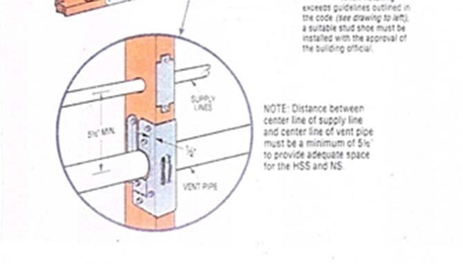
72 Standpipes shall extend not less than 18 but not greater than 42 Drainage and Vent Systems Vent and branch vent pipes shall be graded, connected, and supported to allow moisture and condensate to drain back to the soil or waste pipe by gravity. P Within each plumbing system, not less than one stack vent or a vent stack shall extend outdoors to the open air. P Open vent pipes that extend through a roof shall be terminated not less than 6 above roof. P The island fixture vent shall connect to the fixture drain as required for an individual or common vent. The vent shall rise vertically to above the drainage outlet of the fixture being vented before offsetting horizontally or vertically downward. The vent or branch vent for multiple island fixture vents shall extend not less than 6 inches above the highest island fixture being vented before connecting to the outside vent terminal. Plumbing 72


73 Air admittance valves shall be located not less than 4 above the horizontal branch drain or fixture drain being vented. Stack type air admittance valves shall be located not less than 6 above the flood level rim of the highest fixture being vented. The air admittance valve shall be located within the maximum developed length permitted for the vent. The air admittance valve shall be installed not less than 6 inches above insulation materials where installed in attics. Horizontal drainage piping shall be installed in uniform alignment at uniform slopes not less than ¼ per foot for 3 diameter and less, and not less than 1/8 per foot for diameters of 4 or more Floor drains shall have waste outlets not less than 2 in diameter and removable. P All one and two family dwellings shall have a backwater valve installed to prevent the possibility of sewage backup into the residence. Backwater valves shall be installed with access. Section 5-50A Plumbing 73
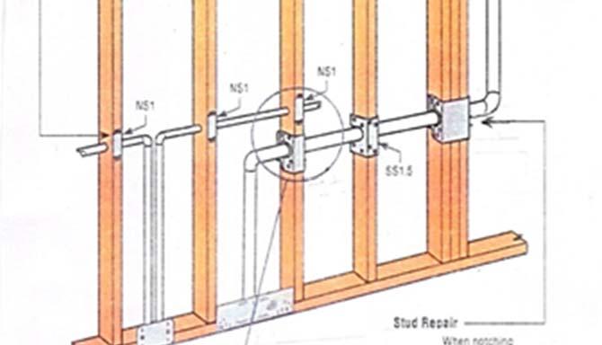
74 Sumps and Ejectors Building sub-drains that cannot be discharged to the sewer by gravity flow shall be discharged into a tightly covered and vented sump from which the liquid shall be lifted and discharged into the building gravity drainage system by automatic pumping equipment or other approved method. A check valve and full open valve located on the discharge side of the check valve shall be installed in the pump or ejector discharge piping between the pump or ejector and the gravity drainage system Drilling and Notching In the process of installing or repairing any part of a plumbing and drainage installation, the finished floors, walls, ceilings, tile work, or any other part of the building or premises that must be changed or replaced shall be left in a safe structural condition in accordance with the requirements of the building portion of this code. P Wood-framed structural members shall not be drilled, notched or altered in any manner except as provided in Sections R502, R602, R802, and R802. P In concealed locations, where piping, other than cast-iron or galvanized steel, is installed through holes or notches in studs, joists, rafters, or similar members less than 1 ½ from the nearest edge of the member, the pipe shall be protected by steel shield plates. P Pipes passing through concrete or cinder walls and floors, cold-formed steel framing or other corrosive material shall be protected against external corrosion by a protective sheathing or wrapping or other means that will withstand any reaction from lime and acid of concrete, cinder, or other corrosive material. Plumbing 74

75 Plumbing 75


76 76
77 Gas Piping Systems The test pressure to be used shall be not less than 3 psig of design pressure. G The test duration shall be not less than 10 minutes. G Piping shall not be installed in or through a ducted supply, return or exhaust, or a clothes chute, chimney or gas vent, dumbwaiter or elevator shaft. Piping installed downstream of the point of delivery shall not extend through any townhouse unit other than the unit served by such piping. G Portions of a piping system installed in concealed locations shall not have unions, tubing fittings, right and left couplings, bushings, compression couplings, and swing joints made by combinations of fittings. G In concealed locations, where piping other than black or galvanized steel is installed through holes or notches, in wood studs, joists, rafters or similar members less than 1 1/2 from the nearest edge of the member, the pipe shall be protected by shield plates. G The shut-off valve shall be located in the same room as the appliance. The shut-off valve shall be within 6 of the appliance and shall be installed upstream of the union, connector or quick disconnect device it serves. Such shut-off valves shall be provided with access. Appliance shutoff valves located in the firebox of a fireplace shall be installed in accordance with the appliance manufacturer s instructions. G Every meter shall be equipped with a shut-off valve located on the supply side of the meter. G Sewer Lateral Minimum 4 sch 40 pipe for sewer lateral. There shall be a clean out near the junction of the building drain and building sewer. Such cleanouts may be installed outside of the building within 5 of the building wall. All one and two family dwellings shall have a backwater valve installed to prevent the possibility of sewage backup into the residence. Backwater valves shall be installed with access. Nixa Ordinance Section 5-50A Where trenches are excavated such that the bottom of the trench forms the bed for the pipe, solid and continuous load bearing support shall be provided between joints. Where over-excavated, the trench shall be backfilled to the proper grade with compacted earth, sand, fine gravel or similar granular material. Piping shall not be supported on rocks or blocks at any point. Rocky or unstable soil shall be brought to the proper grade with suitable compacted granular material. P Backfill shall be free from discarded construction material and debris. Backfill shall be free from rocks, broken concrete and frozen chunks until the pipe is covered by not less than 12 of tamped earth. P Plumbing 77

78 Mechanical General Requirements M1301 Appliances shall be accessible for inspection, service, repair and replacement without removing permanent construction, other appliances or any other piping or ducts not connected to the appliance being serviced, repaired or replaced. M Attics containing appliances shall be provided with an opening and a clear and unobstructed passageway large enough to allow removal of the largest appliance, but not less than 30 high and 22 wide and not more than 20 long measured along the centerline of the passageway from the opening to the appliance. The passageway shall have continuous solid flooring less than 24 wide. A level service space at least 30 deep and 30 wide shall be present along all sides of the appliance where access is required. The clear access opening dimensions shall be a minimum of 20 by 30, and large enough to allow removal of the largest appliance.m Mechanical 78
79 When a furnace is installed in an under floor area, it is suspended a minimum of 6 above grade or installed on a slab a minimum 4 thick. M Equipment installed in pits or excavated areas do not come in direct contact with the surrounding soil. Soils held back a minimum 12 from the equipment. When depth exceeds 12 below adjacent grade, the walls of the pit are lined with concrete or masonry extending a minimum 4 above grade. A passageway is provided large enough to remove the largest piece of equipment, but no less than 22 x36 required to access equipment in under-floor areas and no longer than 20 in length. A 30 x30 working space is provided. Appliances having an ignition source shall be elevated such that the source of ignition is not less than 18 above the floor in garages. M Appliances shall not be installed in a location subject to vehicle damage except where protected by approved barriers. M Condensate from all cooling coils or evaporators shall be conveyed from the drain pan outlet to an approved place of disposal. M Refrigerant circuit access ports located outdoors shall be fitted with locking type tamper resistant caps or shall be otherwise secured to prevent unauthorized access. M Two permanent openings, one commencing within 12 of the top and one commencing within 12 of the bottom of the enclosure, shall be provided. The openings shall communicate directly, or by ducts, with the outdoors or spaces that freely communicate with the outdoors. Mechanical 79
 installed outside the conditioned space have all seams and joints, both longitudinal and transverse, sealed.")


80 Duct Installation M1601 Joints, seams, and fittings, of ducts sealed with tapes, mastic, or other approved means. Ducting (including enclosed stud bays or joist cavities used to transport air) installed outside the conditioned space have all seams and joints, both longitudinal and transverse, sealed. Flex duct support with 1 ½ strap every 4 or per manufacturer s specifications. Mechanical Metal ducts shall be supported by ½ wide 18 gage metal straps or 12 gage galvanized wire at intervals not exceeding 10 feet or other approved means. M Fuel burning appliances shall be vented to the outdoors in accordance with their listing and label and manufacturer s installation instructions except appliances listed and labeled for unvented use. M Joints between sections of connector piping and connections to flue collars and draft hood outlets shall be fastened by one of the following methods: G Sheet metal screws 2. Vent connectors of listed vent material assembled and connected to flue collars or draft hood outlets in accordance with the manufacturer s instructions. 3. Other approved means. A vent connector shall be installed without dips or sags and shall slope upward toward the vent or chimney at least ¼ per foot. 80

81 A Type B or L gas vent shall terminate at least 5 feet in vertical height above the highest connected appliance draft hood or flue collar. G Mechanical 81


82 Water Heaters M2005 Fuel fired water heaters shall not be installed in a room used as a storage closet. Water heaters located in a bedroom or bathroom shall be installed in a sealed enclosure so that combustion air will not be taken from the living space. M Where a storage tank type water heater or a hot water storage tank is installed in a location where water leakage from the tank will cause damage. P Water heaters having an ignition source shall be elevated such that the source of ignition is not less than 18 inches above the floor. M Appliances shall not installed in a location subject to vehicle damage except where protected by approved barriers. M Exhaust Systems M1501 Mechanical The primary intent of this section is to avoid exhausting contaminants into areas that may be occupied by people or into concealed spaces such as attics and crawl spaces where moisture can damage the building components. The air removed by every mechanical exhaust system shall be discharged to the outdoors. Air shall not be exhausted into an attic, soffit, ridge vent or crawl space. M Clothes dryers shall be exhausted in accordance with the manufacturer s instructions. M Dryer exhaust systems shall be independent of all other systems and shall convey the moisture to the outdoors. M The maximum length of the exhaust duct shall be 35 from the connection to the transition duct from the dryer to the outlet terminal. Where fittings are used, the maximum length of the exhaust duct shall be reduced in accordance with Table M


83 Exhaust ducts shall have a smooth interior finish and constructed of metal. The duct shall be 4 nominal in diameter. M Exhaust ducts shall be supported at intervals not to exceed 12 feet and shall be secured in place. Ducts shall not be joined with screws or similar fasteners that protrude more than 1/8 into the inside of the duct. M Range hoods shall discharge to the outdoors through a single wall duct. The duct serving the hood shall have a smooth interior surface, shall be air tight, shall be equipped with a back draft damper, and shall be independent of all other exhaust systems. Ducts serving range hoods shall not terminate in an attic or crawl space or areas inside the building. M Fireplaces Zero clearance fireplaces shall be installed in accordance with manufacturer s installation instructions. Mechanical 83
84 Final Residential Inspection Checklist This checklist is not intended to be all inclusive but rather, a guide to assist you in preparing for your final inspection. Final Checklist Permit and approved plans are on site for the inspector. All site work will be completed before calling for a final inspection. House numbers are plainly visible from the street minimum 4 and a contrasting color. Final grade is a minimum 6 fall in 10. A minimum of 2 trees. Front or back Check for cracked and or broken concrete in sidewalks, driveways. Verify that water, gas, and electric meter are operational. Outdoor receptacles protected by GFCI and provided with in-use weather proof covers. Seal all exterior holes in walls and roofs. They should be weather tight. Backflow preventer is required on all irrigation systems. Vacuum breakers type hose bibs. All exterior lighting fixtures are installed correctly and are outdoor types. Crawl space access should be at least 18 x24. Remove all debris from crawl space. Floor girders are supported on piers. HVAC duct work is properly supported. Plumbing drain waste has correct slope & is supported. Backwater valve on main plumbing waste line is installed. Floor joist have not been notched. Attic access is 22 x30. Check attic insulation. Foam plastic insulation is covered with a thermal barrier. Verify all HVAC, plumbing, and mechanical vents terminate outside. Circuit breakers in main electrical service panels and subpanels are to be properly labeled. No unused knockout in electrical panel. Circuit breaker amperage to be within listed operating range of a/c equipment All electric outlets must be trimmed out. No suspended lighting fixtures within 8 of rim of bath tub. Test electrical outlets for proper wiring, continuity, GFCI, AFCI working condition. Distance between lighting and shelving in storage closets. All mechanical equipment will function properly. Equipment shut off valves and vents will be installed with proper clearances and support and slope. Adequate combustion air is required. Smoke and Carbon Monoxide detectors are tested. 84
85 Check for water leaks at all plumbing fixtures. Provide minimum size access hole, for whirl pool tubs. Locks and hardware will be installed on all doors and windows. All doors will be provided with landings. Provide proper handrails and guardrails at all decks, stairs and platforms. Final Checklist 85
86 Construction Sediment & Erosion Control Guidelines As you may or may not be aware, the EPA with the help of MoDNR has instituted a storm water pollution prevention program entitled: National Pollution Discharge Elimination System (NPDES). Within this NPDES program is information outlining the Municipal Separate Storm Sewer System (MS4) program. The document contains requirements that: any municipality, county or other form of government that has a population of 10,000 or more has a Duty to Comply. The City of Nixa, as a regulated small MS4 has been given this Duty to Comply. Among other things, the City of Nixa is required to: develop, implement, and enforce a storm water management program and plan (SWMP) designed to reduce the discharge of pollutants from the permittee s (City of Nixa) regulated small MS4 to the maximum extent practicable, to protect water quality, and to satisfy the appropriate water quality requirements of the Missouri Clean Water Law. This handout contains guidelines and procedures sufficient for typical One & Two Family construction. It is not intended to address all circumstances that can occur during construction. The goal of this handout is to educate home builders so they can eliminate or reduce the amount of sediment that leaves construction sites and is deposited onto City streets and into the storm sewer system. Since our streets and storm sewer systems convey storm water to lakes and rivers, it is important that we keep these sediments and pollutants off City streets and out of the City s storm sewer system keeping sediment out of our lakes and rivers Best Management Practices: Also known as BMP s, these include but are not limited to; temporary vehicle tracking pads, silt fence, seeding, erosion control blankets, construction phasing or any other device or procedure that helps reduce erosion and sediment loss. Installation Sequencing: The following is the order in which most BMP s are to be utilized: 1. Grass Buffer Strips Ensure that the existing grass buffer strip along the curb lines are not disturbed. If grass is already established, and a buffer strip of 10 feet wide can be left in place, we would ask you to do so. 2. Inlet Protection -Ensure that all storm inlets that receive storm water runoff from your lot are properly protected. 3. Perimeter Control Devices such as silt fence, wattles, or straw bales must be properly installed on all areas where runoff leaves your site. Sediment & Erosion Control 4. All debris that is tracked off site onto the city street is to be removed at the end of each work day. 5. Grading/Excavating All BMP s should be installed prior to any grading or excavation. Dewatering for any trenching or excavation must be done in such a manner as to not deposit sediment downstream. Wattles, filter logs, sedimentation basins or some other means of removing sediment from dewatering must be used prior to discharging water off site. Discharge water should be clear. 6. Stockpiles Perimeter control should be installed around all stock piles. 7. Backfill and rough grading Care should be taken to avoid disturbing the grass buffer strips 86
87 8. Maintenance All BMP s should be maintained so the devices are functioning properly. All sediment should be removed from the streets, gutters and inlets at the end of each work day and after each rain event in which sedimentation occurs. 9. Final Grading All BMP s should be left in place until the site has adequate vegetation established. 10. Seeding or Sodding Should be done as soon as practicable. Permit Holders Responsibility: 1. If a lot is part of a subdivision, the NPDES permit holder for that development must comply with said permit regulations and SWPPP for the life of the project (until such time the permit can be terminated). 2. Ensure that adequate BMP s are in place and functioning until the project is complete. 3. Provide periodic inspection (as outlined in the permit) of BMP s at least once a week and after significant rainfalls. 4. Maintain all BMP s in working order. Remove sediment from inlet protection, perimeter control and other devices as needed. Maintenance requirements: 1. Maintain the grass buffer behind the curb at all times. 2. All perimeter controls that are: collapsed, torn down, or ineffective, are to be replaced or repaired as needed. 3. Remove accumulated sediment from perimeter control BMP s when sediment reaches 1/3 the height of the device. 4. Remove accumulated sediment from inlet protection when it accumulates. Inspections City: The City of Nixa will conduct erosion and sediment control inspections in conjunction with routine building inspections to ensure that the appropriate erosion and sediment control measures are in place and properly secured. The first inspection will occur during footing inspection. It is expected that: the grass buffer strip is maintained, inlet protection and perimeter control be installed, stockpiles protected, and vehicle tracking pads installed (if practicable). BMP s that are not installed or are installed improperly will result in a failed footing inspection. At all subsequent inspections, the BMP s will be subject to inspection to make sure they are working properly. If at any time during construction, sediment deposits are found off the construction site, a stop work order may be issued until the deposit(s) are removed and the proper BMP s have been established. Upon final completion of the project the entire site must be properly stabilized. This can be done through sodding or seed and straw on the entire site. Only when vegetation is adequately established may the sediment control devices be removed. Construction BMP s: The following items give examples of the types of BMP s that should be on every site. Additional BMP s may be required depending on the site, its topography, location, layout, etc. Sediment & Erosion Control 87
88 Boulevard Vegetation: The City of Nixa requests that during new home construction, the boulevard area (the right of way behind the curb to the beginning of the lot line) be vegetated or stabilized the entire time during construction. If the lot has already been graded and has turf grass established, then all that is requested during construction is to leave a 10 grass strip behind the curb when the excavation for the house begins. If this area has not been seeded or if work is required in the boulevard, then additional BMP s may be required to prevent sediment from leaving the property. This boulevard vegetation acts as a buffer strip and helps prevent sediment from being discharged into the streets and storm sewer system. Perimeter Control: Perimeter control is required on all downstream areas of the site where runoff could leave the site. Items that can be used for perimeter control include but are not limited to: silt fence, wattles (fiber logs or silt soxx), seeded soil berm, or straw bales. Silt Fence is the most common type of perimeter control used. To be effective the silt fence must be installed correctly. To achieve this, the bottom of the fence must be installed in a 6 inch deep trench and anchored with dirt spoils from trenching. Wattles (also known as fiber rolls, fiber logs, silt soxx or sediment logs) are made of straw or wood fiber bound by a net to form the shape of a tube. They are typically 6 to 12 inches in diameter and 8 to 10 feet long (or can be laid continuous as perimeter protection). The wattles are held in place by staking. The wattles are easy to install and work great for providing perimeter control next to sidewalks or curb and gutter. Straw bales work as excellent perimeter control to prevent sediment from running into wetlands or low areas if correctly installed with the binding strings on the sides of the bales not next to the ground. Inlet Protection: Inlet protection is required on all storm sewer inlets (curb inlet and area inlets) located downstream of the construction site where storm water runoff may enter. The inlet protection must be installed prior to disturbing the ground, and only removed when vegetation on the lot is adequately established. Miscellaneous Items: Sediment & Erosion Control Other pollution control items that need to be addressed during construction include: site waste control, concrete washout, and dewatering. During construction, all construction waste on the site should be put in an approved container with a lid. Care should be taken to prevent debris and garbage from being blown off site. Hazardous materials such as gas, oils, paints and solvents should be stored in proper containers to prevent leaks and should be disposed of properly. A concrete washout area should be constructed in a manner & location so as to not discharge off site. Washing concrete out into the street or into storm water inlets is considered an illegal discharge. Dewatering is another construction item that needs to be addressed. All water from dewatering practices must be clear before it is discharged off site. If the water is turbid or sediment laden it must be treated with appropriate BMP s before discharging offsite. This may include using a filter bag, dewatering into a sedimentation basin or into a grass swale where the water can infiltrate into the ground. Sediment laden water that is discharged off site is considered an illegal discharge. For more information concerning the City of Nixa s Sediment & Erosion Control Ordinance or the MS4 program; contact the City of Nixa Building Regulations Department at (417) , or the City of Nixa Public Works Department at (417) , or online 88


89 Proper Silt Fence Installation Proper Waddle or Fiber Roll Installation Sediment & Erosion Control 89


90 Proper Curb Inlet Protection Installation Proper Area Inlet Protection Installation Sediment & Erosion Control 90