Construction Procedures
|
|
|
- Fay Blake
- 5 years ago
- Views:
Transcription

1 Construction Procedures 2016 Rev
2 Contents Introduction Base Row Layout Drainage and Backfill Compaction... 7 Subsequent Rows... 8 In Pictures Variations.. 11 Step by Step. 12 Tool Lists


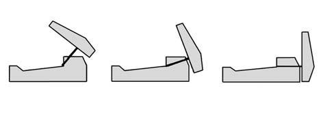
3 Introduction This manual presents the methods and procedures necessary for the proper erection of a LOCK+LOAD retaining wall. problems later during the service life of the masonry wall structure. The LOCK+LOAD wall system provides uniform compaction from the face to the far end of the soil reinforcement creating a monolithic mass of reinforced soil faced with 5500 psi steel reinforced concrete. Second, each LOCK+LOAD module is independently stable and does not stack upon the lower wall modules. This allows the wall structure to consolidate as it is being erected and therefore eliminates unwanted stress in the wall face and soil reinforcement. Third, LOCK+LOAD places the soil reinforcement (geo-grid etc.) at the mid-point of the panel where the grid is contact only with the backfill (just as it is everywhere else in the fill) and so cannot be damaged by being sandwiched between rigid masonry blocks. Each LOCK+LOAD module consists of two pieces, a panel and counterfort that are easily assembled at the project site; as shown in the picture above. LOCK+LOAD also has several unique aspects that require procedures different and at times in direct contravention of procedures commonly used in the building of other masonry block retaining walls. First and most importantly, LOCK+LOAD allows and requires full compaction all the way to the face of the wall (back of the panel). This is required because the reinforced concrete fascia is held in place by friction between the backfill and the counterfort. Typical masonry wall procedures require only light compaction within three feet of the wall face to avoid misalignment due to compaction forces. This zone of light compaction may cause The Vertical locking force on the LOCK+LOAD counterfort is always larger than the horizontal loads placed upon the wall panel allowing large compaction equipment to be used in close proximity to the wall face. 3


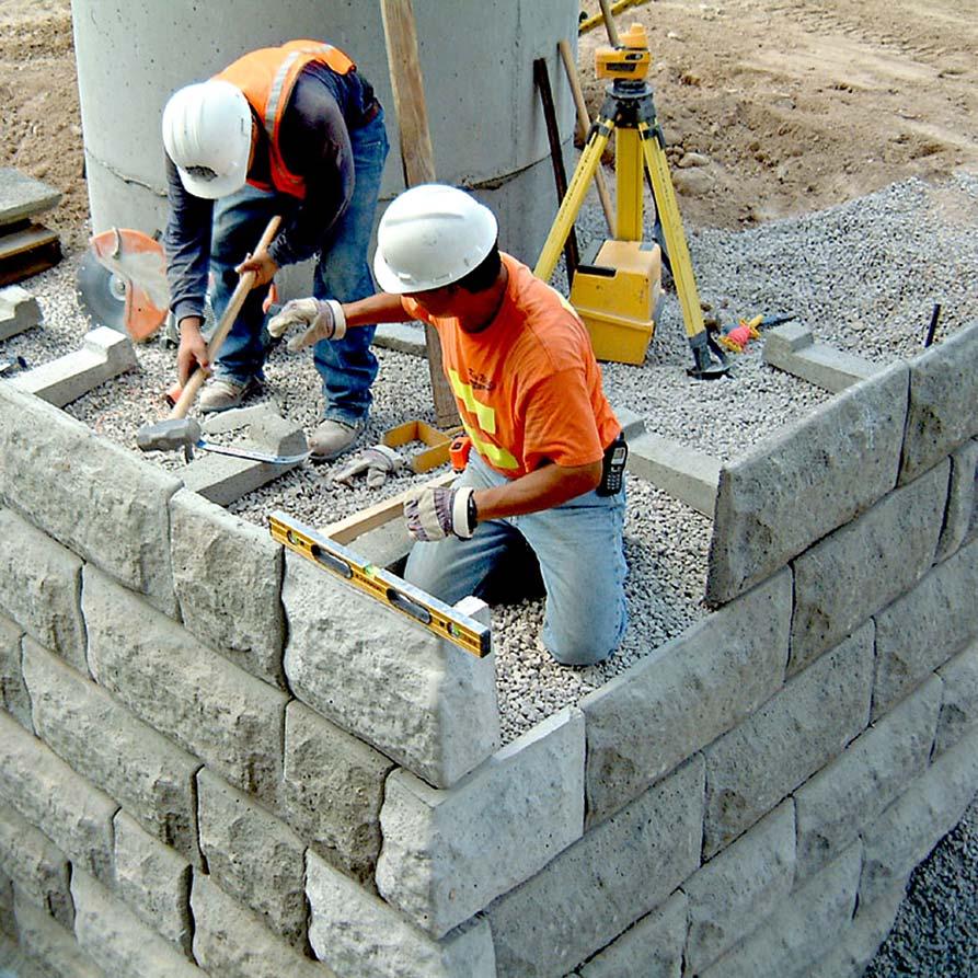
4 Layout Base Row Consult Engineer: Locate survey control points and confirm with the engineer that foundation soils have adequate bearing capacity for the wall height and then if necessary strengthen the foundation where required. Once foundation condition, wall plan and schedule is approved construction may begin. Excavate for the foundation pad: Remove surface vegetation and organic soils and then excavate a minimum 36 wide foundation to 6 below base elevation. If there are elevation steps in the foundation cut each step 16 higher than the next lower level. Access to a laser level this will greatly accelerate this process allowing grade to be checked all along the wall alignment. Other leveling devices may be used, but must be accurate. Foundation cut is a minimum of 36 wide to allow for a drainage pipe at the foundation level behind the counterforts or geo-grid. Drain system placement, is site, and soil specific and must be constructed in accordance with the plan. Set Bottom Row: Except for special circumstances always begin the building a wall from the lowest point of the alignment. Set one panel at each end of the wall section to be constructed. Check panel with survey markers for correct position from survey hub. Place carpenters level on back of panel and plumb by adding or subtracting grading material under counterfort until panel is vertical. Place level on top of panel and level horizontally in the same manner. Check top elevation of both panels on each end of wall segment being constructed with laser level to ensure run will be level. Compact foundation pad: Place ¾ Minus stone 6 deep or as required and compact to 95% Modified Proctor (typically a minimum of 4 passes with a 750 lb or larger reversible vibrating plate compactor). When the base pad is compacted layout panels face down along the wall alignment and attach counterforts. 4

5 Base Row cont. Secure a metal stake at each, set and leveled, panel ( 50 to 80 ft apart ) and run a string line the entire distance of wall segment to be constructed. Additional stakes at may be added to eliminate sag in the string line. Double check alignment, with laser or survey instrument. Now set the intervening panels along the string line. At this point, the top rear of panels will vary slightly off the string line. Adjust panel alignment by adding or subtracting gravel from underneath each counterfort until all panels align with string. If adding material under counterfort, make sure to tamp material tight. Height adjustment, if necessary, is conducted in the same manner adding or subtracting grading material. Slight variations of panels exceeding string line height, can be adjusted by tapping the top of the panel with a sledge hammer using a piece of scrap lumber to prevent chipping of the concrete (similar to setting bricks in mortar). Low panels can be adjusted up by tipping them forward and adding gravel under base of panel Use wedges between the counterfort head and the panel back to remove play and make the module rigid. to raise its elevation. Invest the necessary few minutes to perfect the alignment of the bottom row as it will save time later and helps assure a beautiful, strait, level, aligned wall. After some practice this process becomes quick, efficient, and productive. Accurate alignment and quality compaction are the difference between a good and excellent wall installation. 5
 non-engineered walls the drainpipe will be located at the rear of the counterfort and on the leveling pad (lowest elevation).")


6 Drainage & Backfill Place drainpipe: and drainage stone (aggregate) as specified on the plans, or as approved by engineer. On short (4 ft & less) non-engineered walls the drainpipe will be located at the rear of the counterfort and on the leveling pad (lowest elevation). On walls using geo-grid it may be at the backend of the geo-grid. Check the plans! For rows that will contain soil reinforcement the grid is placed after the first lift of fill is compacted so that geo grid is located at about the mid-point of the wall panel. Backfill : Start by placing backfill material over the tail of the counterfort first. Keep a minimum of 2.0 ft. of select 3/4 clear crushed rock material behind wall face for the foundation of the next row. Beyond this use the specified backfill material. Placement is approximate and need not be perfect. Panel rows should be back filled and compacted in two lifts of ~8 with the second lift rising to approximately 2 above panels top edge so that the compacted soil will consolidate to top of panel. Make minor field adjustments as necessary. Once select fill material is placed over the counterforts the specified backfill can be placed, leveled and compacted in ~8 lifts within the reinforced soil zone using heavy equipment. Take care not to displace the wall alignment or damage soil reinforcement. 6

7 Compaction Compact in 8 lifts using a plate compactor of 750 lbs. minimum, since the ability to compact ~18 of soil is required to erect a row of panels two lifts will be required. If a smaller compactor is used lifts must be reduced to 8 maximum and each coarse of panels compacted in three lifts. Compaction to 95% Modified Proctor is required and should be checked and verified by the Geotech. For granular crushed rock typically a minimum of 4 passes of the plate compactor will be required. Compact along the horizontal distance of the wall, and then proceed to back of the rein forced fill zone. Finally finish with the plate compactor up to and abutting the wall face. Note: This differs from typical modular block wall systems that specify Light Equipment compaction within 3 to 5 behind the wall face. LOCK+LOAD retaining walls require compaction to the wall face, because the counterfort is Even better compaction equipment are large reversible diesel plate compactors with operating weights of 900 to 1100 lbs. [Examples: Wacker models (BPU-3345) or Multi Quip (MVH-200DA) or equivalent]. Roller compactors can safely be used to within 16 of the wall face. All compaction activity always begins with compacting over the tail of the counterfort first locking it into place. the facings attachment to the soil mass. Safety dictates keeping large ride on rollers a minimum of 16 behind the wall face and using the large plate compactors to compact this area. For taller walls local codes may require that this no ride zone increase. 7

8 Subsequent Rows Leveling for Next Row: Using a flat point shovel scrape along the first 5 of wall face using the top of the previous coarse as a guide until level. Note: PANELS DO NOT STACK!!! Back needs to be level with the top of previous panel and compacted. The 1 gap at the base of the next panel is for isolation, movement during a seismic event, and to allow for mass consolidation in taller walls. Repeat layout & align step 4, backfill step 6 and, compact step 7, etc. 8


9 Subsequent Rows cont. Geo-grid Placement: When installing geo-grid in the reinforced soil mass, backfill only approximately ½ the way up panel back making sure that the fill is evenly distributed and about level over the whole grid area. Compact, this lift of fill being careful over the counterforts. Roller compactors may not be used to compact on the first lift over the, barley covered, counterforts since they may be damaged. Once compacted and ~leveled place geogrids with grid directional strength, perpendicular to the wall face. Check against the plans to insure that the geo-grid is the proper strength and length for its position in the retaining wall structure. Place the geogrid so that a minimum of 3 inches remains vertical and in contact with the panel back. Now carefully backfill over the grid, to the top of wall panel, keeping the geo-grid tight and free of wrinkles., A minimum of 2 foot of select material is to be maintained at the wall face. Compact as previously described beginning over the tail of the counterfort to the panel back and then toward the back end of the geo-grid Insure that the geogrid remains in contact with the panel back after compaction. When the back fill is compacted to specification and leveled to the top of the panels the compaction should be checked and approved by the engineer, as required, before construction proceeds. Once approved this construction sequence repeats for the next and subsequent rows until the wall is completed. 9

10 The Steps In Pictures 10


11 Variations Radius Inside and Outside: Curve alignment can be accomplished in several ways an easy method for short radii is to use a rope from a single radius point and swinging an arc. Set the first panel and the next panel will abut it and the opposite edge distance is checked with the rope. Longer radius curves generally will be set as off sets from survey stakes. Once several units are set a string line is run along the outside of the panels and slight a variations removed. For tight curves of 8 radius or less: use half wide panels and construct in the same manner as standard curves. Outside corners are made using the LOCK+LOAD corner panels. When possible begin walls at outside corners to minimize panel trimming if on bond erection is required. Note: Corner counterfort may need to be chipped to round the head so that it can be rotated to avoid interference with adjacent panel counterforts. Corners: LOCK+LOAD does not need to be built on bond but if it is required, for aesthetic reasons, the panels will need to be trimmed for inside corners. The need to trim panels is due to the wall batter. On inside corners the length of subsequent rows grows by 40 mm or 1 9/16. Using a diamond blade cut off saw mark cuts on panel back according to the attached detail and trim to lengths required to maintain the split bond. 11


12 Step by Step Retaining Module Assembly Prepare Foundation & Layout 1st Row Compact Over Counterfort Tail First 12
13 Tool Lists Required Tools 1.) String Line 2.) Flat pry bar, (12 wonder nail pulling bar ) 3.) 36 round steel concrete stakes 4.) Flat point shovel 5.) 4-16 Lb. Hammer 6.) 2 ft. Builders Level 7.) String line level (minimum), Rotating Laser level and string line preferred. 8.) Plate Compactor; with 16 in. backfill lift capability (minimum). For example: Wacker BPU 2440 or Equivalent 24 Kn or 5400 lb, centrifugal force or larger, the best results with fewer passes. Note: a smaller compactor is only acceptable on walls 4 ft or less where access for a larger compactor may be difficult and Lifts must be reduced to 8 in maximum with multiple passes. 9.) Scrap lumber, (2 x 4 s). 10.) Always work safely, Safety Glasses, Ear Protection, Hard Hat, Leather Gloves, Leather Work Boots. Recommended Tools 1.) Material Handling Equipment: Front End Loader (skid steer, wheel loader, backhoe) and or Excavator with grading bucket, Dozer etc. for excavation, placement and leveling of backfill. 2.) Ride on Vibratory Roller: Pad-foot recommended for clay and cohesive soils. Smooth drum for granular material. Geo-tech can aid in your selection for soil type and geographic location. 3.) Laser Level: Speeds up leveling process and insures accuracy. 4.) Utility Knife: Used to cut geo-grid in taller wall designs. 5.) 12 or 14 Diamond concrete blade on a Cut Off Saw with water. 13