Introduction.» Demolition Concepts» Concept Design» Final Design» Construction» Health Monitoring
|
|
|
- Hannah Cook
- 5 years ago
- Views:
Transcription

1

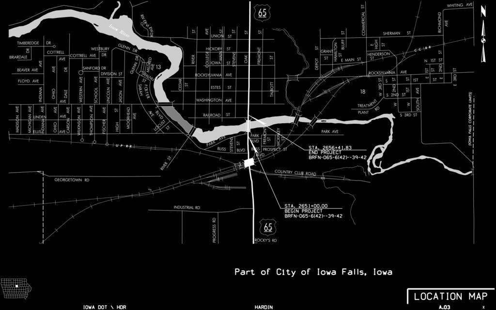
2 Location of Project
3 Introduction» Demolition Concepts» Concept Design» Final Design» Construction» Health Monitoring
4 Existing Bridge» Built in 1928» 255-foot Open Spandrel Concrete Arch Bridge» 24-foot Roadway and Two Sidewalks» Deck Supported by R/C Floor Beams RIGHT PROFILE

5 Existing Bridge» Rehabilitated 7 Different Occasions» Needed Widening and Strengthening» Replace Rather than Rehabilitate
6 Concept Stage Type Study» Identify Constraints and Constructability Concerns» Identify Feasible Demolition Concepts» Identify Feasible Replacement Alternatives» Cost» Timeline for Construction


7 Constraints and Constructability Issues» Site Access


8 Constraints and Constructability Issues» Historic Church NW Corner of Bridge Listed on the National Register of Historic Places Photo by: iafalls.com


9 Constraints and Constructability Issues» Dam Maintain Water Level
10 Demolition Concepts Assumptions» No Environmental Restrictions» Access to River is Available» No Prohibition on Use of Engineered Explosives» Vibration Monitoring Required» Cost versus Clean up

11 Actual Demolition» Started mid October 2010 and Finished mid December 2010.» Lowered the Iowa River with Cooperation of the Downstream Dam» Constructed an Access Road and Causeway Utilizing a System of Steel Bridge Beams and Crane Mats over the Open Water

12 Actual Demolition» Constructed a System to Protect the Sanitary Sewer Lines» Demolished the Bridge using the Causeway» Deck and Columns were Demolished using two Excavators with Hydraulic Breakers» Each excavator started at the Center of the Bridge

13 Actual Demolition» Demolished the Arches Using the same Excavators with a Mounted Hammer» Arch Pieces were Broken Down and Hauled Off-Site by Truck» Vibration Monitoring was Provided at the Adjacent Church and Residences

14 Bridge Replacement Alternatives» City of Iowa Falls Scenic City River Cruises is a Major City Attraction Several Types of Bridges that Span Across Iowa River Photo by: EmpressBoatClub.com


15 Bridge Replacement Alternatives Washington Avenue Concrete Arch Bridge Photo by: HistoricBridges.org
16 Bridge Replacement Alternatives Assumptions» No Environmental Restrictions» Access to River Launch Segmental Barges Erect a Suitable 150-ton Crane» Vibration Monitoring Required

17 Bridge Replacement Alternatives Two Span Prestressed Concrete Alternative» Easiest to Construct» Drilled Shaft at Pier Eliminates Need for Cofferdam» Drilled Shaft at Abutments Reduces Vibration Impacts» Less Rock Excavation than other Alternatives» Most Economical Option
18 Bridge Replacement Alternatives Simple Span Haunched Girder Alternative» Non-conventional Super Type» Heavy Girder Pieces» Require Temporary Bents or Falsework» Substantial Rock Excavation» Require Lead Time for Fabrication

19 Bridge Replacement Alternatives Partial Thru Steel Arch Alternative» Easier to Construct Relative to Concrete Arch» Shorter Construction Period than Concrete Arch» Require Temporary Bents, Falsework or Tied-Back Systems to Construct» Additional Inspection and Maintenance of Suspenders» Requires Construction Engineering

20 Bridge Replacement Alternatives Concrete Deck Arch Alternative» Most Difficult/Complex to Construct» Rib Shortening Issues» Requires Temporary Bents or Falsework or Tied- Back Systems» Longest Construction Period» Requires Construction Engineering


21 Bridge Replacement Alternatives The Alternatives Existing Concrete Deck Arch Prestressed Concrete Girder Haunched Steel Girder Partial Thru Steel Arch Concrete Deck Arch

22 New Bridge Aerial View
23 Final Design Considerations» Tight Geometrics» Bridge Footprint» Retaining Walls and Rock Cuts» Substructure Sizing and Sustainability» Protection of the Superstructure
24 Tight Geometrics

25 Existing Church Retaining Wall

26 Micropile Retaining Wall
27 Rock Cut Support Walls
28 Rock Cut and Concrete Fascia Walls
29 Aesthetics and Renderings» Kimball Olson Aesthetics coordinator Iowa DOT» Used to convey Size Perspective Spatial relationships» Useful in Design and Presentation to the General Public

30 Rendering Showing Trail

31 Actual Bridge
32 Deck and Hanger Cables» Floor Beam and Stinger system suspended from the Arch Rib» End Floor Beams frame directly into the Arch Rib» Deepened Exterior Stringer / Stiffening Girder Distributes vehicular loads from deck to multiple hanger cables Minimize local live load deflections
33 Arch Design» Grade 50 Weathering Steel with Protective Coatings» Built in Replacement of Hanger Cables» Pinned Bearings» Wide aspect ratio Length to Width ratio = 4 No trussed sway bracing.

34 Interior Floor Beam and Hangers
35 End Floor Beam


36 Pinned Bearings» Net Zero Change in Steel Weight from a Fixed Connection» Reduced Footing Size» Minimized Impacts to Surrounding Properties
37 Foundations» Issues: Existing Bridge Showed Signs of Undermining Arch Skew Back Behave Differently than the Retaining Wall Abutment.» Solutions: High Capacity Micropiles Separate Foundations Tied-back Abutment Lightweight Backfill

38 Foundation Issues» Existing Bridge Undermining

39 Micropiles

40 Abutment and Micropile Schematic

41 Pin and Hanger Steel Tolerances» Construction tolerance issues during fabrication of the Pins and Hangers: ASHTO Requirement: 0.031» Maximum Difference» As Fabricated» Pin to Pin Plate: 0.04» Pin to Socket: 0.14

42 Pin and Hanger Steel Tolerances» Resolution Perform additional tests on the Pin to Socket connection to quantify permanent deformation under load. 55% Proof load No permanent deformation allowed as measured to nearest Contractor also tested two connections to 100% load

43 Pin and Hanger Steel Tolerances» Observed Deformations Proof load = % load = 0.04» Contractor was allowed to use the pins and sockets as fabricated.

44 Fabricated Bearing Tolerances» Bearing Side Plates Warped out of tolerance Would not allow upper unit to fit with the lower unit» Masonry Plate Curved upward on the edges Would not allow full bearing on the concrete skew back

45 Fabricated Bearing Tolerances» Bearing Side Plates Total conflict 1/4 Fabricator milled 1/8 from upper and lower units Difference was evaluated and deemed acceptable Complicated fit


46 Fabricated Bearing Tolerances» Masonry Plate Maximum gap of 3/4 at the edge Steel erection allowed to proceed Jacked and grouted prior to pouring the concrete deck

47 Health Monitoring» Iowa State University - Dr. Brent Phares

48