September Greenland Well Pump Station Replacement 143 Post Road Greenland, New Hampshire BID# CITY OF Portsmouth New Hampshire
|
|
|
- Robert Gibson
- 5 years ago
- Views:
Transcription

1 September 2016 CITY OF Portsmouth New Hampshire Greenland Well Pump Station Replacement 143 Post Road Greenland, New Hampshire BID# 11-17
2 Division TABLE OF CONTENTS Section Number 0 BIDDING AND CONTRACT REQUIREMENTS Advertisement For Bids A-1 Information for Bidders A-2 Bid Form A-3 Bid Bond A-4 Notice of Award B-1 Agreement B-2 Payment Bond B-3 Performance Bond B-4 Notice to Proceed B-5 Change Order B-6 Certificate of Substantial Completion B-7 Certificate of Final Completion B-8 Contractor s Affidavit B-9 Contractor s Final Release B-10 General Conditions Supplementary Conditions Permits GENERAL REQUIREMENTS Scope and Sequence of Work Control of Work and Materials Special Provisions Measurement and Payment Submittals Structural Tests and Inspections Dust Control Existing Fences Cleaning Up Operations and Maintenance Manuals SITE WORK Ductile Iron Pipe And Fittings for Water Mains Groundwater Observation Wells Selective Structure Demolition Abandonment of Existing Water Mains Dewatering i
3 Division ii Section Number Support of Excavation Earthwork Rock Excavation and Disposal Riprap Insulation For Pipeline Hydrants and Valves Service Connections Connections to Existing Water Mains Processed Gravel Roadway Chain Link Fence Loaming and Seeding CONCRETE Cast-In-Place Concrete MASONRY Masonry METALS Miscellaneous Metals THERMAL AND MOISTURE PROTECTION Foundation Insulation Fully Adhered Elastomeric Sheet Roofing Green Roof Joint Sealants FINISHES Painting EQUIPMENT Vertical Turbine Pumps Chemical Feed Equipment SPECIAL CONSTRUCTION Precast Concrete Utility Building Process Control Strategies 13410
4 Division Section Number Field Instruments and Equipment Control Panels Variable Frequency Drives Programmable Controllers Wireless Telemetry System MECHANICAL Process Valves and Appurtenances Process Pipe and Fittings Chemical Storage Tanks Plastic Process Pipe & Fittings ELECTRICAL Basic Electrical (Division 16 Specifications provided on the plans) E-5 and E-5.1 Appendix A HAZARDOUS MATERIALS SURVEY Appendix B Asbestos Demolition/Renovation Notification Form N.H. Department of Environmental Services Air Resources Division Appendix C Underground Propane Tanks Appendix D Existing Building Photos Appendix E Well Diagrams END OF SECTION O:\Portsmouth NH\Greenland Well\Design\Specs\Table of Contents.docx iii
5 A-1.1 ADVERTISEMENT FOR BIDS City of Portsmouth, New Hampshire Owner Department of Public Works, 680 Peverly Hill Road, Portsmouth, NH Address Sealed BIDS for the construction of the Greenland Well Pump Station Replacement will be received at the City of Portsmouth Purchasing Department, City Hall, 1 Junkins Avenue, Portsmouth, NH 03801, until 11:00 a.m. local time on Thursday, October 6, BIDS will then be publicly opened and read aloud at said office and time. The Project includes, but is not limited to, installing a new precast concrete building with a green roof to house a new well pump, motor, variable frequency drive and associated pump column and discharge piping, chemical feed equipment, instrumentation and controls, and a new outdoor standby generator. Other work includes, but is not limited to, the demolition of the existing well pump house, miscellaneous site work, and electrical work. There will be a mandatory pre-bid meeting on September 15, 2016 at 1:00 PM. The pre-bid meeting will be held in the first floor conference room located at the City of Portsmouth Department of Public Works, 680 Peverly Hill Road, Portsmouth, New Hampshire, and followed by a visit to the project site. 1. Completion time for the project will be calculated as calendar days from the date specified in the Notice to Proceed as follows: 280 calendar days for substantial completion. 310 calendar days for final completion. Liquidated damages will be in the amount of $ for each calendar day of delay from the date established for substantial completion, and $ for each calendar day of delay from the date established for final completion. Liquidated damages in the amount of $ shall also be assessed for each calendar day the City s existing or replacement well supply is not in service beyond the time that is allotted per the contract documents. 2. Each General Bid shall be accompanied by a Bid Security in the amount of 5% of the Total Bid Price. 3. The successful Bidder must furnish 100% Performance and Payment Bonds and will be required to execute the Contract Agreement within 10 days following notification of the acceptance of his Bid. 4. No Bidder may withdraw a Bid within 60 days after the actual date of opening thereof. 08/03/2016
6 5. The owner reserves the right to reject any and all bids, to accept any bid, to waive any informatlity on bids received, and to omit any item or items it may deem to be in the best interest of the Owner. 6. Any questions regarding bidding should be directed to the Purchasing Department at All questions regarding the design plans and specifications must be provided in writing to Andrea David, Weston & Sampson at by 4:00 pm September 22, Electronic Contract Documents (Plans, Specification, and Addenda) may be obtained at the City s website Contract Documents may also be viewed and downloaded as a Portable Document Format (PDF) file free of charge at Copies may be obtained by completing an order online or by calling with payment of printing fee for each set. Copies may be shipped for an additional charge. All payments for printing and shipping are nonrefundable. Completed orders may be picked up at the offices of Accent Printing located at 75 Third Avenue, Waltham, MA ( ) or 99 Chelmsford Road, North Billerica, MA ( ), from 9 a.m. to 4 p.m. Copies may also be shipped to prospective bidders for an additional charge to cover handling and mailing fees. Addenda to this project, if any, including written answers to questions will not be provided directly to bidders, but will be posted on City s website and listed under the project heading by 4:00 pm on September 29, Bidders are responsible for basing their bids on the complete set of Contract Documents associated with the project and made available on the City s website. END OF SECTION 08/03/2016
7 A-2.1 INFORMATION FOR BIDDERS BIDS will be received by City of Portsmouth (herein called the "OWNER"), at Purchasing Department, 1 Junkins Ave., Portsmouth, NH until 11:00 am on October 6, 2016 and then at said office publicly opened and read aloud. Each BID must be submitted in a sealed envelope, addressed to: City of Portsmouth Purchasing Department at City Hall, 1 Junkins Ave., Portsmouth, NH Each sealed envelope containing a BID must be plainly marked on the outside as BID for Bid No Greenland Well Pump Station Replacement and the envelope should bear on the outside the BIDDER's name, address, and license number if applicable and the name of the project for which the BID is submitted. If forwarded by mail, the sealed envelope containing the BID must be enclosed in another envelope addressed to the OWNER at City of Portsmouth Purchasing Department, City Hall, 1 Junkins Ave., Portsmouth, NH All BIDS must be made on the required BID form and be based on the complete set of CONTRACT DOCUMENTS including all ADDENDA. All blank spaces for BID prices must be filled in, in ink or typewritten, and the BID form must be fully completed and executed when submitted. Only one copy of the BID form is required. The OWNER may waive any informalities or minor defects or reject any and all BIDS. Any BID may be withdrawn prior to the above scheduled time for the opening of BIDS or authorized postponement thereof. Any BID received after the time and date specified shall not be considered. No BIDDER may withdraw a BID within 60 days after the actual date of the opening thereof. Should there be reasons why the contract cannot be awarded within the specified period, the time may be extended by mutual agreement between the OWNER and the BIDDER. BIDDERS must satisfy themselves of the accuracy of the estimated quantities in the BID SCHEDULE by examination of the site and a review of the drawings and specifications including ADDENDA. After BIDS have been submitted, the BIDDER shall not assert that there was a misunderstanding concerning the quantities of WORK or of the nature of the WORK to be done. The OWNER shall provide to BIDDERS prior to BIDDING, all information which is pertinent to, and delineates and describes, the land owned and rights-of-way acquired or to be acquired. The CONTRACT DOCUMENTS contain the provisions required for the construction of the PROJECT. Information obtained from an officer, agent, or employee of the OWNER or any other person shall not affect the risks or obligations assumed by the CONTRACTOR or relieve him from fulfilling any of the conditions of the contract. 08/03/2016
8 A-2.2 Each BID must be accompanied by a BID BOND payable to the OWNER in the amount of five percent (5%) of the total amount of the BID. As soon as the BID prices have been compared, the OWNER will return the BONDS of all except the three lowest responsible BIDDERS. When the AGREEMENT is executed, the bonds of the two remaining unsuccessful BIDDERS will be returned. The BID BOND of the successful BIDDER will be retained until the PAYMENT BOND and PERFORMANCE BOND have been executed and approved, after which it will be returned. A certified check may be used in lieu of a BID BOND. A PERFORMANCE BOND and a PAYMENT BOND, each in the amount of 100 percent of the CONTRACT PRICE, with a corporate surety approved by the OWNER, will be required for the faithful performance of the contract. Attorneys-in-fact who sign BID BONDS or PAYMENT BONDS and performance BONDS must file with each BOND a certified and effective dated copy of their power of attorney. The party to whom the contract is awarded will be required to execute the AGREEMENT and obtain the PERFORMANCE BOND and PAYMENT BOND within ten (10) calendar days from the date when NOTICE OF AWARD is delivered to the BIDDER. The NOTICE OF AWARD shall be accompanied by the necessary AGREEMENT and BOND forms. In case of failure of the BIDDER to execute the AGREEMENT, the OWNER may at his option consider the BIDDER in default, in which case the BID BOND accompanying the proposal shall become the property of the OWNER. The OWNER within ten (10) days of receipt of acceptable PERFORMANCE BOND, PAYMENT BOND and AGREEMENT signed by the party to whom the AGREEMENT was awarded shall sign the AGREEMENT and return to such party an executed duplicate of the AGREEMENT. Should the OWNER not execute the AGREEMENT within such period, the BIDDER may by WRITTEN NOTICE withdraw his signed AGREEMENT. Such notice of withdrawal shall be effective upon receipt of the notice by the OWNER. The NOTICE TO PROCEED shall be issued within ten (10) days of the execution of the Agreement by the OWNER. Should there be reasons why the NOTICE TO PROCEED cannot be issued within such period, the time may be extended by mutual agreement between the OWNER and CONTRACTOR. If the NOTICE TO PROCEED has not been issued within the ten (10) day period or within the period mutually agreed upon, the CONTRACTOR may terminate the AGREEMENT without further liability on the part of either party. The OWNER may make such investigations as he deems necessary to determine the ability of the BIDDER to perform the WORK, and the BIDDER shall furnish to the OWNER all such information and data for this purpose as the OWNER may request. The OWNER reserves the right to reject any BID if the evidence submitted by, or investigation of, such BIDDER fails to satisfy the OWNER that such BIDDER is properly qualified to carry out the obligations of the AGREEMENT and to complete the WORK contemplated therein. A conditional or qualified BID will not be accepted. Award will be made to the lowest responsive and responsible BIDDER. 08/03/2016
9 A-2.3 All applicable laws, ordinances, and the rules and regulations of all authorities having jurisdiction over construction of the PROJECT shall apply to the contract throughout. Each BIDDER is responsible for inspecting the site and for reading and being thoroughly familiar with the CONTRACT DOCUMENTS. The failure or omission of any BIDDER to complete any of the foregoing shall in no way relieve any BIDDER from any obligation in respect to his BID. Further, the BIDDER agrees to abide by the requirements under Executive Order No , as amended, including specifically the provisions of the equal opportunity clause set forth in the GENERAL CONDITIONS. The low BIDDER shall supply the names and addresses of major material SUPPLIERS and SUBCONTRACTORS when requested to do so by the OWNER. MANUFACTURERS EXPERIENCE Wherever it may be written that an equipment manufacturer must have a specified period of experience with his product, equipment which does not meet the specified experience period can be considered if the equipment supplier or manufacturer is willing to provide a bond or cash deposit for the duration of the specified time period which will guarantee replacement of that equipment in the event of failure. SAFETY AND HEALTH REGULATIONS This project is subject to all of the Safety and Health Regulations (CFR 29 Part 1926 and all subsequent amendments) as promulgated by the U.S. Department of Labor on June 24, Contractors are urged to become familiar with the requirements of these regulations. NON-DISCRIMINATION IN EMPLOYMENT Contracts for work under this proposal will obligate the contractors and sub-contractors not to discriminate in employment practices. COPIES OF THE CONTRACT There shall be at least three (3) executed copies of the Contract to be distributed as follows: a) One (1) copy each to the Owner, Engineer, Contractor. NON-RESIDENT CONTRACTORS The successful bidder, if a corporation established under laws other than the State of New Hampshire, shall file, at the time of the execution of the contract, with the Owner, notice of the name of its resident attorney, appointed as required by the laws of the State of New Hampshire. 08/03/2016
10 A-2.4 The successful bidder, if not a resident of New Hampshire, and not a corporation, shall file, at the time of execution of the contract, with the Owner a written appointment of a resident of the state of New Hampshire, having an office or place of business therein, to be his true and lawful attorney upon whom all lawful processes in any actions or proceedings against him may be served; and in such writing, which shall set forth said attorney's place of residence, shall agree that any lawful process against him which is served on said attorney shall be of the same legal force and validity as if served on him and that the authority shall continue in force so long as any liability remains outstanding against him in New Hampshire. The power of attorney shall be filed in the office of the Secretary of State if required, and copies certified by the Secretary shall be sufficient evidence thereof. Such appointment shall continue in force until revoked by an instrument in writing, designating in a like manner some other person upon whom such processes may be served, which instrument shall be filed in the manner provided herein for the original appointment. A Non-resident Contractor shall be deemed to be: a) A person who is not a resident of the State of New Hampshire. b) Any partnership that has no member thereof resident of the State of New Hampshire. c) Any corporation established under laws other than those of the State of New Hampshire. BIDDERS QUALIFICATIONS No award will be made to any Bidder who cannot meet all of the following requirements: A. BIDDER shall not have defaulted nor turned the work over to the bonding company on any contract within three years prior to the bid date. B. BIDDER shall maintain a permanent place of business. C. BIDDER shall have adequate personnel and equipment to perform the work expeditiously. D. BIDDER shall have suitable financial status to meet obligations incidental to the work. E. BIDDER shall have appropriate technical experience satisfactory to the Engineer and the Division in the class of work involved. F. BIDDER shall be registered with the Secretary of State to do business in New Hampshire. G. BIDDER shall have performed to the satisfaction of the Engineer and the Division on previous contracts of a similar nature. H. BIDDER shall not have failed to complete previous contracts on time, including approved time extensions. 08/03/2016 A-2.5
11 WITHDRAWAL OF BIDS Prior to Bid Opening, bids may be withdrawn upon written or telegraphic request of the Bidder provided confirmation of any telegraphic withdrawal over the signature of the Bidder is placed in the mail and postmarked prior to the time set for Bid Opening. Bid documents and security of any Bidder withdrawing their bid in accordance with the foregoing conditions will be returned. END OF SECTION 08/03/2016
12 A-3.1 BID Proposal of (hereinafter called "BIDDER"), organized and existing under the laws of the State of doing business as (Corporation, Partnership, Individual) To the City of Portsmouth (hereinafter called "OWNER"). In compliance with your Advertisement for Bids, BIDDER hereby proposes to perform all WORK for the construction of Greenland Well Pump Station Replacement in strict accordance with the CONTRACT DOCUMENTS, within the time set forth therein, and at the prices stated below. By submission of this BID, each BIDDER certifies, and in the case of a joint BID each party thereto certifies as to his own organization, that this BID has been arrived at independently, without consultation, communication, or agreement as to any matter relating to the BID with any other BIDDER or with any competitor. BIDDER hereby agrees to commence WORK under this contract on or before a date to be specified in the NOTICE TO PROCEED and to complete the PROJECT within: 280 consecutive calendar days for substantial completion. 310 consecutive calendar days for final completion. Liquidated damages will be in the amount of $ for each calendar day of delay from the date established for substantial completion and $ for each calendar day of delay from the date established for final completion, as provided in Section 18 of the General Conditions. Liquated damages in the amount of $ shall also be assessed for each calendar day the City s existing or replacement well supply is not in service beyond the time that is allotted per the contract documents. BIDDER acknowledges receipt of the following ADDENDUM: 08/03/2016 A-3.2
13 The Bidder shall state below what works of a similar character to that of the proposed contract he has performed, and provide such references as will enable the Owner to judge his experience, skill, and business standing. All questions must be answered and the data given must be clear and comprehensive. This statement must be notarized. If necessary, add separate sheets. 1. Name of Bidder. 2. Permanent Main Office address. 3. When organized? 4. Where incorporated? 5. Is bidder registered with the Secretary of the State to do business in New Hampshire? 6. For how many years has your firm engaged in the contracting business under its present name? Also state names and dates of previous firm names, if any. 7. Contracts on hand. (Schedule these, showing gross amount of each contract and the approximate anticipated dates of completion.) 8. General character of work performed by your company. 9. Have you ever failed to complete any work awarded you in the scheduled contract time, including approved time extensions? (Yes) (No). If so, where and why? 10. Have you ever defaulted on a contract? (Yes) (No). If so, where and why? 11. Have you ever had liquidated damages assessed on a contract? (Yes) (No). If so, where and why? 12. List the more important contracts recently executed by your company, stating approximate cost for each, and the month and year completed. 13. List your major equipment available for this contract. 14. List your key personnel such as Project Superintendent and foreman available for this contract. 15. List any subcontractors whom you would expect to use for the following (unless this work is to be done by your own organization): a. Civil Engineering: b. Utility Installation: c. Other work: 08/03/2016
14 A With what banks do you conduct business? Do you grant the Engineer permission to contact this (these) institutions? (Yes) (No) NOTE: Bidders may be required to furnish their latest financial statement as part of the award process. Respectfully submitted: Signature Address Title Date Being duly sworn, deposes and says that he is of (Name of Organization) and that the answers to the foregoing questions and all statements contained therein are true and correct. Sworn to before me this day of, 20 My commission expires Notary Public (Seal - If BID is by Corporation) ATTEST: BIDDER agrees to perform all the work described in the CONTRACT DOCUMENTS for the following unit prices or lump sum: NOTE: BIDS shall include sales tax and all other applicable taxes and fees. 08/03/2016
15 A-3.4 BID SCHEDULE Item 1. BASE PROPOSAL: Bidder agrees to perform all of the work described in the specification and shown on the plans for the sum of: ($ ) Dollars and Cents (All entries shall be made clearly in ink or typewritten. Amounts are to be shown in both words and figures. In case of discrepancy, the amount shown in words will govern.) The BASE PROPOSAL shall include all labor, materials, bailing, shoring, removal, overhead, profit, insurance, engineering costs, etc., to cover the finished work of the several kinds called for. The Bidder understands that all bids for this project are subject to the applicable bidding laws of the State of New Hampshire. The contract will be awarded to the lowest responsible and eligible bidder. Bidder understands that the Owner reserves the right to reject any or all bids and to waive any informalities in the bidding. END OF SECTION 08/03/2016
16 A-4.1 BID BOND KNOW ALL MEN BY THESE PRESENTS, that we, the undersigned, held and firmly bound unto City of Portsmouth in the penal sum of as Principal, and as Surety, are hereby as OWNER for the payment of which, well and truly to be made, we hereby jointly and severally bind ourselves, successors and assigns. Signed, this day of The Condition of the above obligation is such that whereas the Principal has submitted to a certain BID, attached hereto and hereby made a part hereof to enter into a contract in writing, for the Greenland Well Pump Station Replacement NOW, THEREFORE, (a) If said BID shall be rejected, or (b) If said BID shall be accepted and the Principal shall execute and deliver a contract in the Form of Contract attached hereto (Properly completed in accordance with said BID) and shall furnish a BOND for faithful performance of said contract, and for the payment of all persons performing labor or furnishing materials in connection therewith, and shall in all other respects perform the agreement created by the acceptance of said BID, then this obligation shall be void, otherwise, the same shall remain in force and effect; it being expressly understood and agreed that the liability of the Surety for any and all claims hereunder shall, in no event, exceed the penal amount of this obligation as herein stated. 08/03/2016
17 A-4.2 The Surety, for value received, hereby stipulates and agrees that the obligations of said Surety and its BOND shall be in no way impaired or affected by any extension of the time within which the OWNER may accept such BID; and said Surety does hereby waive notice of any such extension. IN WITNESS WHEREOF, the Principal and the Surety have hereunto set their hands and seals, and such of them as are corporations have caused their corporate seals to be hereto affixed and these presents to be signed by their proper officers, the day and year first set forth above. Principal By: Surety By: IMPORTANT-Surety companies executing BONDS must appear on the Treasury Department's most current list (Circular 570 as amended) and be authorized to transact business in the state of New Hampshire. END OF SECTION 08/03/2016
18 TO: B-1.1 NOTICE OF AWARD Dated, 20 (BIDDER) ADDRESS: OWNER'S PROJECT NO: 1108 PROJECT: Greenland Well Pump Station Replacement OWNER'S CONTRACT NO: CONTRACT FOR: Greenland Well Pump Station Replacement (Insert name of contract as it appears in the Bid Documents) You are notified that your Bid for the above Contract has been dated considered. You are the apparent successful bidder and have been awarded a contract for: Greenland Well Pump Station Replacement The Contract Price of your contract is (Indicate total Work, alternates or sections of Work awarded) Dollars ($ ). 3 copies of each of the proposed Contract Documents (except Drawings) accompany this Notice of Award. The same number of sets of the Drawings will be delivered separately or otherwise made available to you immediately. You must comply with the following conditions precedent within ten days of receiving this Notice of Award. 1. You must deliver to the OWNER all of the fully executed counterparts of the Agreement including all the Contract Documents. This includes the sets of Drawings. Each of the Contract Documents must bear your signature on (the cover) (every) page. 2. You must deliver with the executed Agreement the Contract Security (Bonds) as specified in the Information for Bidders and General Conditions. 08/03/2016
19 B (List other conditions precedent). Proof of Insurance Coverage Failure to comply with these conditions within the time specified will entitle OWNER to consider your bid abandoned, to annul this Notice of Award and to declare your Bid Security forfeited. Within ten days after receipt of acceptable performance BOND, payment BOND and agreement signed by the party to whom the Agreement was awarded, the OWNER will return to you one fully signed counterpart of the Agreement with the Contract Documents attached. City of Portsmouth, NH (OWNER) By (AUTHORIZED SIGNATURE) (TITLE) 08/03/2016 ACCEPTANCE OF NOTICE Receipt of the above NOTICE OF AWARD is hereby acknowledged By The day of, 20 By Title Copy to ENGINEER (Use Certified Mail, Return Receipt Requested) END OF SECTION
20 B-2.1 AGREEMENT THIS AGREEMENT, made this day of,20 16 by and between City of Portsmouth, New Hampshire, hereinafter called "OWNER" (Name of Owner) and doing business as (an individual,) or (a partnership,) or (a corporation) hereinafter called "CONTRACTOR". WITNESSETH: That for and in consideration of the payments and agreements hereinafter mentioned: 1. The CONTRACTOR will commence and complete the construction of: Greenland Well Pump Station Replacement (Project) 2. The CONTRACTOR will furnish all of the material, supplies, tools, equipment, labor and other services necessary for the construction and completion of the PROJECT described herein. 3. The CONTRACTOR will commence the work required by the CONTRACT DOCUMENTS within 30 calendar days after the date of the NOTICE TO PROCEED unless the period for completion is extended otherwise by the CONTRACT DOCUMENTS. Completion time for the project will be calculated as calendar days from the date specified in the NOTICE TO PROCEED as follows: 280 calendar days for substantial completion. 310 calendar days for final completion. Liquidated damages will be in the amount of $ date established for substantial completion and $ for each calendar day of delay from the for each calendar day of delay from the date established for final completion. Liquated damages in the amount of $ shall also be assessed for each calendar day the City s existing or replacement well supply is not in service beyond the time that is allotted per the contract documents. 4. The CONTRACTOR agrees to perform all of the WORK described in the CONTRACT DOCUMENTS and comply with the terms therein for the sum of $ or as shown in the BID schedule. 08/03/2016
21 B The term "CONTRACT DOCUMENTS" means and includes the following: (A) ADVERTISEMENT FOR BIDS (B) INFORMATION FOR BIDDERS (C) BID (D) BID BOND (E) NOTICE OF AWARD (F) AGREEMENT (G) PAYMENT BOND (H) PERFORMANCE BOND (I) NOTICE TO PROCEED (J) CHANGE ORDER(S) (K) CERTIFICATION OF SUBSTANTIAL COMPLETION (L) CERTIFICATION OF FINAL COMPLETION (M) CONTRACTORS AFFIDAVIT (N) CONTRACTORS RELEASE (O) GENERAL CONDITIONS (P) SUPPLEMENTAL GENERAL CONDITIONS (Q) SPECIAL CONDITIONS (R) DRAWINGS prepared by: Weston & Sampson Engineers, Inc. numbered 1 through 23, and dated September, (S) SPECIFICATIONS prepared or issued by: Weston & Sampson Engineers, Inc., and dated September, (T) ADDENDA: No., dated, 20 No., dated, 20 No., dated, 20 No., dated, 20 No., dated, 20 08/03/2016
22 B The OWNER will pay to the CONTRACTOR in the manner and at such times as set forth in the General Conditions such amounts as required by the CONTRACT DOCUMENTS. 7. This Agreement shall be binding upon all parties hereto and their respective heirs, executors, administrators, successors, and assigns. IN WITNESS WHEREOF, the parties hereto have executed, or caused to be executed by their duly authorized officials, this Agreement in original on the date first above written. 3 copies, each of which shall be deemed an OWNER: City of Portsmouth, NH By: Name: John P. Bohenko, City Manager (Please type) (SEAL) ATTEST: Name: Title: CONTRACTOR: By: Name: Address: (SEAL) ATTEST: Name: Title: 08/03/2016
23 KNOW ALL MEN BY THESE PRESENTS: that B-3.1 PAYMENT BOND (Name of Contractor) a and (Address of Contractor) (Corporation, Partnership or Individual) (Name of Surety), hereinafter called Principal, (Address of Surety) hereinafter called Surety, are held and firmly bound unto City of Portsmouth, New Hampshire (Name of Owner) 1 Junkins Ave., Portsmouth, NH (Address of Owner) hereinafter called OWNER and unto all persons, firms, and corporations who or which may furnish labor, or who furnish materials to perform as described under the contract and to their successors and assigns, in the total aggregate penal sum of Dollars, ($ ) in lawful money of the United States, for the payment of which sum well and truly to be made, we bind ourselves, our heirs, executors, administrators, successors, and assigns, jointly and severally, firmly by these presents. THE CONDITION OF THIS OBLIGATION is such that whereas, the Principal entered into a certain contract with the OWNER, dated the day of 20, a copy of which is hereto attached and made a part hereof for the construction of: Greenland Well Pump Station Replacement NOW, THEREFORE, if the Principal shall promptly make payment to all persons, firms, and corporations furnishing materials for or performing labor in the prosecution of the WORK provided for in such contract, and any authorized extension or modification thereof, including all amounts due for materials, lubricants, oil, gasoline, coal and coke, repairs on machinery, equipment and tools, consumed or used in connection with the construction of such WORK, and for all labor cost incurred in such WORK including that be a subcontractor, and to any mechanic or materialman lienholder whether it acquires its lien by operation of State or Federal Law; then this obligation shall be void; otherwise to remain in full force and effect. PROVIDED, that beneficiaries or claimants hereunder shall be limited to the subcontractors, and persons, firms, and corporations having a direct contract with the PRINCIPAL or its SUBCONTRACTORS. 08/03/2016
24 B-3.2 PROVIDED FURTHER, that the said Surety for value received hereby stipulates and agrees that no change, extension of time, alteration or addition to the terms of the contract or to the WORK to be performed thereunder or the SPECIFICATIONS accompanying the same shall in any way affect its obligation on this BOND, and it does hereby waive notice of any such change, extension of time, alteration or addition to the terms of the contract or to the WORK or to the SPECIFICATIONS. PROVIDED, FURTHER that no suit or action shall be commenced hereunder by any claimant: (a) Unless claimant, other than one having a direct contract with the PRINCIPAL shall have given written notice to any two of the following: The PRINCIPAL, the OWNER, or the SURETY above named within ninety (90) days after such claimant did or performed the last of the work or labor, or furnished the last of the materials for which said claim is made, stating with substantial accuracy the amount claimed and the name of the party to whom the materials were furnished, or for whom the work or labor was done or performed. Such notice shall be served by mailing the same by registered mail or certified mail, postage prepaid, in an envelope addressed to the PRINCIPAL, OWNER, or SURETY, at any place where an office is regularly maintained for the transaction business, or served in any manner in which legal process may be served in the state in which the aforesaid project is located, save that such service need not be made by a public officer. (b) After the expiration of one (1) year following the date on which PRINCIPAL ceased work on said CONTRACT, it being understood, however, that if any limitation embodied in the BOND is prohibited by any law controlling the construction hereof, such limitation shall be deemed to be amended so as to be equal to the minimum period of limitation permitted by such law. PROVIDED, FURTHER, that it is expressly agreed that this BOND shall be deemed amended automatically and immediately, without formal and separate amendments hereto, upon amendment to the Contract not increasing the contract price more than 20 percent, so as to bind the PRINCIPAL and the SURETY to the full and faithful performance of the Contract as so amended. The term "Amendment", wherever used in this BOND and whether referring to this BOND, the contract or the loan Documents shall include any alteration, addition, extension or modification of any character whatsoever. PROVIDED FURTHER, that no final settlement between the OWNER and the CONTRACTOR shall abridge the right of any beneficiary hereunder, whose claim may be unsatisfied. 08/03/2016
25 B-3.3 IN WITNESS WHEREOF, this instrument is executed in 3 counterparts, each one of (number) which shall be deemed an original, this day of, 20. ATTEST: By: (SEAL) (Principal) Secretary BY Principal (Address) By: Witness as to Principal (Address) (Surety) ATTEST: BY Attorney - in - Fact By Witness as to Surety (Address) (Address) NOTE: Date of BOND must not be prior to date of Contract. If CONTRACTOR is partnership, all partners should execute BOND. IMPORTANT: Surety companies executing BONDS must appear on the Treasury Department's most current list (Circular 570 as amended) and be authorized to transact business in the State of New Hampshire. END OF SECTION 08/03/2016
26 KNOW ALL MEN BY THESE PRESENTS: B-4.1 PERFORMANCE BOND that, (Name of Contractor) with place of business at, (Address of Contractor) a and (Corporation, Partnership or Individual) (Name of Surety) (Address of Surety), hereinafter called PRINCIPAL,, with place of business at, hereinafter called SURETY, are held and firmly bound unto City of Portsmouith, New Hampshire, (Name of Owner) with place of business at Department of Public Works, 680 Peverly Hill Road, Portsmouth, NH 03801, (Address of Owner) hereinafter called OWNER, in the penal sum of Dollars ($ ), in lawful money of the United States, for the payment of which sum well and truly to be made, we bind ourselves, successors, and assigns, jointly and severally, firmly by these presents. THE CONDITION OF THIS OBLIGATION is such that whereas, the Principal entered into a certain contract with the OWNER, dated the day of 20, a copy of which is hereto attached and made a part hereof for the construction of: Greenland Well Pump Station Replacement NOW, THEREFORE, if the Principal shall well, truly and faithfully perform its duties, all the undertakings, covenants, terms, conditions, and agreements of said contract during the original term thereof, and any extension thereof which may be granted by the OWNER, with or without notice to the Surety and during the one year guaranty period, and if the PRINCIPAL shall satisfy all claims and demands incurred under such contract, and shall fully indemnify and save harmless the OWNER from all costs and damages which it may suffer by reason of failure to do so, and shall reimburse and repay the OWNER all outlay and expense which the OWNER may incur in making good any default, then this obligation shall be void: otherwise to remain in full force and effect. PROVIDED, FURTHER, that the said surety, for value received hereby stipulates and agrees that no change, extension of time, alteration or addition to the terms of the contract or to WORK to be performed thereunder or the specifications accompanying the same shall in any wise affect 08/03/2016
27 its obligation on this BOND, and it does hereby waive notice of any such change, extension of time alteration or addition to the terms of the contract or to the WORK or to the specifications. PROVIDED, FURTHER, that no final settlement between the OWNER and the CONTRACTOR shall abridge the right of any beneficiary hereunder, whose claim may be unsatisfied. IN WITNESS WHEREOF, this instrument is executed in 3 counterparts, (number) each one of which shall be deemed an original, this day of 20. ATTEST: (Principal Secretary) (Principal) (SEAL) BY: (Address) By: (Witness as to Principal) (Address) ATTEST: BY: (Surety) Attorney-in Fact BY: (Witness as to Surety) (Address) (Address) NOTE: Date of BOND must not be prior to date of Contract. If CONTRACTOR is partnership, all partners should execute BOND. IMPORTANT: Surety companies executing BONDS must appear on the Treasury Department's most current list (Circular 570 as amended) and be authorized to transact business in the State of New Hampshire. END OF SECTION 08/03/2016
28 B-5.1 NOTICE TO PROCEED Dated, 20 TO: (Contractor) ADDRESS: OWNER'S PROJECT NO.: PROJECT: Greenland Well Pump Station Replacement OWNER'S CONTRACT NO.: CONTRACT FOR: Greenland Well Pump Station Replacement You are notified that the Contract Time under the above contract will commence to run on, 20. By that date, you are to start performing your obligations under the Contract Documents. In accordance with paragraph 3 of the Agreement, the dates of Substantial Completion and Final Completion are, 20 and, 20, respectively. Before you may start any Work at the site, paragraph 27 of the General Conditions provides that you and Owner must each deliver to the other (with copies to ENGINEER) certificates of insurance which each is required to purchase and maintain in accordance with the Contract Documents. Copy to ENGINEER (Use certified Mail, return Receipt Requested) By (owner) (Authorized Representative) (Title) ACCEPTANCE OF NOTICE Receipt of the above NOTICE TO PROCEED is hereby acknowledged by: by: (Contractor) This the, 20 Employee Identification Number: (Title) END OF SECTION 08/03/2016
29 B-6.1 CHANGE ORDER No. PROJECT: Greenland Well PS Replacement DATE OF ISSUANCE: OWNER: (Address) CONTRACTOR: OWNER s Project No. CONTRACT FOR: ENGINEER Weston & Sampson Engineers. ENGINEER s Project No You are directed to make the following changes in the Contract Documents. Description: Purpose of Change Order: Justification: Attachments: (List documents supporting change) $ $ $ $ $ CHANGE IN CONTRACT PRICE Original Contract Price Previous Change Orders Contract Price prior to this Change Order Net Increase (Decrease) of this Change Order Contract Price with all approved Change Orders CHANGE IN CONTRACT TIME Original Contract Time (days or date) Net change from previous Change Orders (days) Contract Time prior to this Change Order (days or date) Net Increase (decrease) this Change Order (days) Contract Time with all Change Orders (days or date) This document will become a supplement to the CONTRACT and all provisions will apply hereto. The attached Contractor s Revised Project Schedule reflects increases or decreases in Contract Time as authorized by this Change Order. 08/03/2016
30 Stipulated price and time adjustment includes all costs and time associated with the above described change. Contractor waives all rights for additional time extension for said change. Contractor and Owner agree that the price(s) and time adjustment(s) stated above are equitable and acceptable to both parties. RECOMMENDED: APPROVED: APPROVED: By: By: By: Engineer Owner Contractor Date Date Date END OF SECTION 08/03/2016
31 B-7.1 CERTIFICATE OF SUBSTANTIAL COMPLETION OWNER's Project No ENGINEER's Project No Project Greenland Well Pump Station Replacement CONTRACTOR Contract For Contract Date This Certificate of Substantial Completion applies to all Work under the Contract Documents or to the following specified parts thereof: To And To City of Portsmouth, New Hampshire (Owner) (Contractor) The Work to which this Certificate applies has been inspected by authorized representatives of OWNER, CONTRACTOR and ENGINEER, and that Work is hereby declared to be substantially complete in accordance with the Contract Documents on. (Date of Substantial Completion) A tentative list of items to be completed or corrected is attached hereto. This list may not be allinclusive, and the failure to include an item in it does not alter the responsibility of CONTRACTOR to complete all the Work in accordance with the Contract Documents. The items in the tentative list shall be completed or corrected by CONTRACTOR within calendar days of the above date of Substantial Completion. The responsibilities between OWNER and CONTRACTOR for security, operation, safety, maintenance, heat, utilities, insurance and warranties shall be as follows: RESPONSIBILITIES: OWNER: CONTRACTOR: 08/03/2016
32 The following documents are attached to and made a part of this Certificate: This certificate does not constitute an acceptance of Work not in accordance with the Contract Documents nor is it a release of CONTRACTOR's obligation to complete the Work in accordance with the Contract Documents. Executed by ENGINEER on 20 By Weston & Sampson Engineers, Inc. (Engineer) CONTRACTOR accepts this Certificate of Substantial Completion on, 20 By (Contractor) OWNER accepts this Certificate of Substantial Completion on, 20 By City of Portsmouth, New Hampshire (Owner) END OF SECTION 08/03/2016
33 B-8.1 CERTIFICATE OF FINAL COMPLETION Owner s Project No Engineer s Project No Project Greenland Well Pump Station Replacement Owner: City of Portsmouth, New Hampshire Contractor: Engineer: Weston & Sampson Engineers, Inc. Agreement Date: Notice to Proceed Date: Contractual Substantial Completion Date as modified by Change Orders: Actual Substantial Completion Date: Contractual Final Completion Date as modified by Change Orders: The Work to which this Certificate applies has been inspected by authorized representatives of Owner, Contractor, Engineer and NHDES, the punch list has been completed and the Work of the Contract is hereby declared to be Finally Complete in accordance with the Contract Documents on: Date of Final Completion This Certificate does not constitute an acceptance of any Work not in accordance with the Contract Documents nor is it a release of Contractor s obligation to complete the Work in accordance with the Contract Documents. The Warranty for all Work completed subsequent to the date of Substantial Completion expires one year from the date of this Final Acceptance. Executed by Engineer on:, 20 By: Contractor Accepts this Certificate of Final Completion on:, 20 By: Owner Accepts this Certificate of Final Completion on:, 20 By: NHDES Accepts this Certificate of Final Completion on:, 20 By: END OF SECTION 08/03/2016
34 B-9.1 CONTRACTOR'S AFFIDAVIT STATE OF: COUNTY OF: Before me, the undersigned, a (Notary Public, Justice of Peace, Alderman) in and for said County and State personally appeared, (Individual, Partner or duly who being duly sworn according to law authorized representative of corporate contractor) deposes and says that the cost of all the Work, and outstanding claims and indebtedness of whatever nature arising out of the performance of the contract between City of Portsmouth, NH and (Owner) (Contractor) of (Address) dated for the construction of the Greenland Well Pump Station Replacement (Project Name) and necessary appurtenant installations have been paid in full. (Individual, Partner, or duly authorized representative of corporate contractor) (Title) Sworn to and subscribed before me this day of, 20 Notary Public END SECTION 08/03/2016
35 B-10.1 CONTRACTOR'S FINAL RELEASE AND WAIVER OF LIEN Project/Owner Contractor Project: Greenland Well Pump Station Replacement Name Address: 143 Post Road Address: Greenland NH City State Zip City State Zip Owner: City of Portsmouth, NH Contractor License: Contract Date: TO ALL WHOM IT MAY CONCERN: For good and valuable consideration, the receipt and sufficiency of which is hereby acknowledged, the undersigned Contractor hereby waives, discharges, and releases any and all liens, claims, and rights to liens against the above-mentioned project, and any and all other property owned by or the title to which is in the name of the above-referenced Owner and against any and all funds of the Owner appropriated and available for the construction of said project, and any and all warrants drawn upon or issued against any such funds or monies, which the undersigned Contractor may have or may hereafter acquire or process as a result of the furnishing of labor, materials, and/or equipment, and the performance of Work by the Contractor on or in connection with said project, whether under and pursuant to the above-mentioned contract between the Contractor and the Owner pertaining to said project or otherwise, and which said liens, claims or rights of lien may arise and exist. The undersigned further hereby acknowledges that the sum of Dollars ($ ) constitutes the entire unpaid balance due the undersigned in Connection with said project whether under said contract or otherwise and that the payment of said sum to the Contractor will constitute payment in full and will fully satisfy any and all liens, claims, and demands which the Contractor may have or assert against the Owner in connection with said contract or project. 08/03/2016
36 Dated this day of 20 Witness to Signature By Title Contractor By Title END OF SECTION 08/03/2016
37 This document has important legal consequences; consultation with an attorney is encouraged with respect to its use or modification. This document should be adapted to the particular circumstances of the contemplated Project and the controlling Laws and Regulations. STANDARD GENERAL CONDITIONS OF THE CONSTRUCTION CONTRACT Prepared by ENGINEERS JOINT CONTRACT DOCUMENTS COMMITTEE and Issued and Published Jointly by AMERICAN COUNCIL OF ENGINEERING COMPANIES ASSOCIATED GENERAL CONTRACTORS OF AMERICA AMERICAN SOCIETY OF CIVIL ENGINEERS PROFESSIONAL ENGINEERS IN PRIVATE PRACTICE A Practice Division of the NATIONAL SOCIETY OF PROFESSIONAL ENGINEERS Endorsed by CONSTRUCTION SPECIFICATIONS INSTITUTE EJCDC C-700 Standard General Conditions of the Construction Contract Copyright 2007 National Society of Professional Engineers for EJCDC. All rights reserved.
38 These General Conditions have been prepared for use with the Suggested Forms of Agreement Between Owner and Contractor (EJCDC C-520 or C-525, 2007 Editions). Their provisions are interrelated and a change in one may necessitate a change in the other. Comments concerning their usage are contained in the Narrative Guide to the EJCDC Construction Documents (EJCDC C-001, 2007 Edition). For guidance in the preparation of Supplementary Conditions, see Guide to the Preparation of Supplementary Conditions (EJCDC C-800, 2007 Edition). Copyright 2007 National Society of Professional Engineers 1420 King Street, Alexandria, VA (703) American Council of Engineering Companies th Street N.W., Washington, DC (202) American Society of Civil Engineers 1801 Alexander Bell Drive, Reston, VA (800) Associated General Contractors of America 2300 Wilson Boulevard, Suite 400, Arlington, VA (703) The copyright for this EJCDC document is owned jointly by the four EJCDC sponsoring organizations and held in trust for their benefit by NSPE. EJCDC C-700 Standard General Conditions of the Construction Contract Copyright 2007 National Society of Professional Engineers for EJCDC. All rights reserved.
39 STANDARD GENERAL CONDITIONS OF THE CONSTRUCTION CONTRACT TABLE OF CONTENTS Article 1 Definitions and Terminology Defined Terms Terminology... 5 Article 2 Preliminary Matters Delivery of Bonds and Evidence of Insurance Copies of Documents Commencement of Contract Times; Notice to Proceed Starting the Work Before Starting Construction Preconstruction Conference; Designation of Authorized Representatives Initial Acceptance of Schedules... 7 Article 3 Contract Documents: Intent, Amending, Reuse Intent Reference Standards Reporting and Resolving Discrepancies Amending and Supplementing Contract Documents Reuse of Documents Electronic Data Article 4 Availability of Lands; Subsurface and Physical Conditions; Hazardous Environmental Conditions; Reference Points Availability of Lands Subsurface and Physical Conditions Differing Subsurface or Physical Conditions Underground Facilities Reference Points Hazardous Environmental Condition at Site Article 5 Bonds and Insurance Performance, Payment, and Other Bonds Licensed Sureties and Insurers Certificates of Insurance Contractor s Insurance Owner s Liability Insurance Property Insurance Waiver of Rights Receipt and Application of Insurance Proceeds EJCDC C-700 Standard General Conditions of the Construction Contract Copyright 2007 National Society of Professional Engineers for EJCDC. All rights reserved. Page i Page
40 5.09 Acceptance of Bonds and Insurance; Option to Replace Partial Utilization, Acknowledgment of Property Insurer Article 6 Contractor s Responsibilities Supervision and Superintendence Labor; Working Hours Services, Materials, and Equipment Progress Schedule Substitutes and Or-Equals Concerning Subcontractors, Suppliers, and Others Patent Fees and Royalties Permits Laws and Regulations Taxes Use of Site and Other Areas Record Documents Safety and Protection Safety Representative Hazard Communication Programs Emergencies Shop Drawings and Samples Continuing the Work Contractor s General Warranty and Guarantee Indemnification Delegation of Professional Design Services Article 7 Other Work at the Site Related Work at Site Coordination Legal Relationships Article 8 Owner s Responsibilities Communications to Contractor Replacement of Engineer Furnish Data Pay When Due Lands and Easements; Reports and Tests Insurance Change Orders Inspections, Tests, and Approvals Limitations on Owner s Responsibilities Undisclosed Hazardous Environmental Condition Evidence of Financial Arrangements Compliance with Safety Program Article 9 Engineer s Status During Construction Owner s Representative EJCDC C-700 Standard General Conditions of the Construction Contract Copyright 2007 National Society of Professional Engineers for EJCDC. All rights reserved. Page ii
41 9.02 Visits to Site Project Representative Authorized Variations in Work Rejecting Defective Work Shop Drawings, Change Orders and Payments Determinations for Unit Price Work Decisions on Requirements of Contract Documents and Acceptability of Work Limitations on Engineer s Authority and Responsibilities Compliance with Safety Program Article 10 Changes in the Work; Claims Authorized Changes in the Work Unauthorized Changes in the Work Execution of Change Orders Notification to Surety Claims Article 11 Cost of the Work; Allowances; Unit Price Work Cost of the Work Allowances Unit Price Work Article 12 Change of Contract Price; Change of Contract Times Change of Contract Price Change of Contract Times Delays Article 13 Tests and Inspections; Correction, Removal or Acceptance of Defective Work Notice of Defects Access to Work Tests and Inspections Uncovering Work Owner May Stop the Work Correction or Removal of Defective Work Correction Period Acceptance of Defective Work Owner May Correct Defective Work Article 14 Payments to Contractor and Completion Schedule of Values Progress Payments Contractor s Warranty of Title Substantial Completion Partial Utilization Final Inspection Final Payment Final Completion Delayed EJCDC C-700 Standard General Conditions of the Construction Contract Copyright 2007 National Society of Professional Engineers for EJCDC. All rights reserved. Page iii
42 14.09 Waiver of Claims Article 15 Suspension of Work and Termination Owner May Suspend Work Owner May Terminate for Cause Owner May Terminate For Convenience Contractor May Stop Work or Terminate Article 16 Dispute Resolution Methods and Procedures Article 17 Miscellaneous Giving Notice Computation of Times Cumulative Remedies Survival of Obligations Controlling Law Headings EJCDC C-700 Standard General Conditions of the Construction Contract Copyright 2007 National Society of Professional Engineers for EJCDC. All rights reserved. Page iv
43 ARTICLE 1 DEFINITIONS AND TERMINOLOGY 1.01 Defined Terms A. Wherever used in the Bidding Requirements or Contract Documents and printed with initial capital letters, the terms listed below will have the meanings indicated which are applicable to both the singular and plural thereof. In addition to terms specifically defined, terms with initial capital letters in the Contract Documents include references to identified articles and paragraphs, and the titles of other documents or forms. 1. Addenda Written or graphic instruments issued prior to the opening of Bids which clarify, correct, or change the Bidding Requirements or the proposed Contract Documents. 2. Agreement The written instrument which is evidence of the agreement between Owner and Contractor covering the Work. 3. Application for Payment The form acceptable to Engineer which is to be used by Contractor during the course of the Work in requesting progress or final payments and which is to be accompanied by such supporting documentation as is required by the Contract Documents. 4. Asbestos Any material that contains more than one percent asbestos and is friable or is releasing asbestos fibers into the air above current action levels established by the United States Occupational Safety and Health Administration. 5. Bid The offer or proposal of a Bidder submitted on the prescribed form setting forth the prices for the Work to be performed. 6. Bidder The individual or entity who submits a Bid directly to Owner. 7. Bidding Documents The Bidding Requirements and the proposed Contract Documents (including all Addenda). 8. Bidding Requirements The advertisement or invitation to bid, Instructions to Bidders, Bid security of acceptable form, if any, and the Bid Form with any supplements. 9. Change Order A document recommended by Engineer which is signed by Contractor and Owner and authorizes an addition, deletion, or revision in the Work or an adjustment in the Contract Price or the Contract Times, issued on or after the Effective Date of the Agreement. 10. Claim A demand or assertion by Owner or Contractor seeking an adjustment of Contract Price or Contract Times, or both, or other relief with respect to the terms of the Contract. A demand for money or services by a third party is not a Claim. 11. Contract The entire and integrated written agreement between the Owner and Contractor concerning the Work. The Contract supersedes prior negotiations, representations, or agreements, whether written or oral. EJCDC C-700 Standard General Conditions of the Construction Contract Copyright 2007 National Society of Professional Engineers for EJCDC. All rights reserved. Page 1 of 62
44 12. Contract Documents Those items so designated in the Agreement. Only printed or hard copies of the items listed in the Agreement are Contract Documents. Approved Shop Drawings, other Contractor submittals, and the reports and drawings of subsurface and physical conditions are not Contract Documents. 13. Contract Price The moneys payable by Owner to Contractor for completion of the Work in accordance with the Contract Documents as stated in the Agreement (subject to the provisions of Paragraph in the case of Unit Price Work). 14. Contract Times The number of days or the dates stated in the Agreement to: (i) achieve Milestones, if any; (ii) achieve Substantial Completion; and (iii) complete the Work so that it is ready for final payment as evidenced by Engineer s written recommendation of final payment. 15. Contractor The individual or entity with whom Owner has entered into the Agreement. 16. Cost of the Work See Paragraph for definition. 17. Drawings That part of the Contract Documents prepared or approved by Engineer which graphically shows the scope, extent, and character of the Work to be performed by Contractor. Shop Drawings and other Contractor submittals are not Drawings as so defined. 18. Effective Date of the Agreement The date indicated in the Agreement on which it becomes effective, but if no such date is indicated, it means the date on which the Agreement is signed and delivered by the last of the two parties to sign and deliver. 19. Engineer The individual or entity named as such in the Agreement. 20. Field Order A written order issued by Engineer which requires minor changes in the Work but which does not involve a change in the Contract Price or the Contract Times. 21. General Requirements Sections of Division 1 of the Specifications. 22. Hazardous Environmental Condition The presence at the Site of Asbestos, PCBs, Petroleum, Hazardous Waste, or Radioactive Material in such quantities or circumstances that may present a substantial danger to persons or property exposed thereto. 23. Hazardous Waste The term Hazardous Waste shall have the meaning provided in Section 1004 of the Solid Waste Disposal Act (42 USC Section 6903) as amended from time to time. 24. Laws and Regulations; Laws or Regulations Any and all applicable laws, rules, regulations, ordinances, codes, and orders of any and all governmental bodies, agencies, authorities, and courts having jurisdiction. 25. Liens Charges, security interests, or encumbrances upon Project funds, real property, or personal property. 26. Milestone A principal event specified in the Contract Documents relating to an intermediate completion date or time prior to Substantial Completion of all the Work. EJCDC C-700 Standard General Conditions of the Construction Contract Copyright 2007 National Society of Professional Engineers for EJCDC. All rights reserved. Page 2 of 62
45 27. Notice of Award The written notice by Owner to the Successful Bidder stating that upon timely compliance by the Successful Bidder with the conditions precedent listed therein, Owner will sign and deliver the Agreement. 28. Notice to Proceed A written notice given by Owner to Contractor fixing the date on which the Contract Times will commence to run and on which Contractor shall start to perform the Work under the Contract Documents. 29. Owner The individual or entity with whom Contractor has entered into the Agreement and for whom the Work is to be performed. 30. PCBs Polychlorinated biphenyls. 31. Petroleum Petroleum, including crude oil or any fraction thereof which is liquid at standard conditions of temperature and pressure (60 degrees Fahrenheit and 14.7 pounds per square inch absolute), such as oil, petroleum, fuel oil, oil sludge, oil refuse, gasoline, kerosene, and oil mixed with other non-hazardous Waste and crude oils. 32. Progress Schedule A schedule, prepared and maintained by Contractor, describing the sequence and duration of the activities comprising the Contractor s plan to accomplish the Work within the Contract Times. 33. Project The total construction of which the Work to be performed under the Contract Documents may be the whole, or a part. 34. Project Manual The bound documentary information prepared for bidding and constructing the Work. A listing of the contents of the Project Manual, which may be bound in one or more volumes, is contained in the table(s) of contents. 35. Radioactive Material Source, special nuclear, or byproduct material as defined by the Atomic Energy Act of 1954 (42 USC Section 2011 et seq.) as amended from time to time. 36. Resident Project Representative The authorized representative of Engineer who may be assigned to the Site or any part thereof. 37. Samples Physical examples of materials, equipment, or workmanship that are representative of some portion of the Work and which establish the standards by which such portion of the Work will be judged. 38. Schedule of Submittals A schedule, prepared and maintained by Contractor, of required submittals and the time requirements to support scheduled performance of related construction activities. 39. Schedule of Values A schedule, prepared and maintained by Contractor, allocating portions of the Contract Price to various portions of the Work and used as the basis for reviewing Contractor s Applications for Payment. EJCDC C-700 Standard General Conditions of the Construction Contract Copyright 2007 National Society of Professional Engineers for EJCDC. All rights reserved. Page 3 of 62
46 40. Shop Drawings All drawings, diagrams, illustrations, schedules, and other data or information which are specifically prepared or assembled by or for Contractor and submitted by Contractor to illustrate some portion of the Work. 41. Site Lands or areas indicated in the Contract Documents as being furnished by Owner upon which the Work is to be performed, including rights-of-way and easements for access thereto, and such other lands furnished by Owner which are designated for the use of Contractor. 42. Specifications That part of the Contract Documents consisting of written requirements for materials, equipment, systems, standards and workmanship as applied to the Work, and certain administrative requirements and procedural matters applicable thereto. 43. Subcontractor An individual or entity having a direct contract with Contractor or with any other Subcontractor for the performance of a part of the Work at the Site. 44. Substantial Completion The time at which the Work (or a specified part thereof) has progressed to the point where, in the opinion of Engineer, the Work (or a specified part thereof) is sufficiently complete, in accordance with the Contract Documents, so that the Work (or a specified part thereof) can be utilized for the purposes for which it is intended. The terms substantially complete and substantially completed as applied to all or part of the Work refer to Substantial Completion thereof. 45. Successful Bidder The Bidder submitting a responsive Bid to whom Owner makes an award. 46. Supplementary Conditions That part of the Contract Documents which amends or supplements these General Conditions. 47. Supplier A manufacturer, fabricator, supplier, distributor, materialman, or vendor having a direct contract with Contractor or with any Subcontractor to furnish materials or equipment to be incorporated in the Work by Contractor or Subcontractor. 48. Underground Facilities All underground pipelines, conduits, ducts, cables, wires, manholes, vaults, tanks, tunnels, or other such facilities or attachments, and any encasements containing such facilities, including those that convey electricity, gases, steam, liquid petroleum products, telephone or other communications, cable television, water, wastewater, storm water, other liquids or chemicals, or traffic or other control systems. 49. Unit Price Work Work to be paid for on the basis of unit prices. 50. Work The entire construction or the various separately identifiable parts thereof required to be provided under the Contract Documents. Work includes and is the result of performing or providing all labor, services, and documentation necessary to produce such construction, and furnishing, installing, and incorporating all materials and equipment into such construction, all as required by the Contract Documents. 51. Work Change Directive A written statement to Contractor issued on or after the Effective Date of the Agreement and signed by Owner and recommended by Engineer ordering an EJCDC C-700 Standard General Conditions of the Construction Contract Copyright 2007 National Society of Professional Engineers for EJCDC. All rights reserved. Page 4 of 62
47 1.02 Terminology addition, deletion, or revision in the Work, or responding to differing or unforeseen subsurface or physical conditions under which the Work is to be performed or to emergencies. A Work Change Directive will not change the Contract Price or the Contract Times but is evidence that the parties expect that the change ordered or documented by a Work Change Directive will be incorporated in a subsequently issued Change Order following negotiations by the parties as to its effect, if any, on the Contract Price or Contract Times. A. The words and terms discussed in Paragraph 1.02.B through F are not defined but, when used in the Bidding Requirements or Contract Documents, have the indicated meaning. B. Intent of Certain Terms or Adjectives: 1. The Contract Documents include the terms as allowed, as approved, as ordered, as directed or terms of like effect or import to authorize an exercise of professional judgment by Engineer. In addition, the adjectives reasonable, suitable, acceptable, proper, satisfactory, or adjectives of like effect or import are used to describe an action or determination of Engineer as to the Work. It is intended that such exercise of professional judgment, action, or determination will be solely to evaluate, in general, the Work for compliance with the information in the Contract Documents and with the design concept of the Project as a functioning whole as shown or indicated in the Contract Documents (unless there is a specific statement indicating otherwise). The use of any such term or adjective is not intended to and shall not be effective to assign to Engineer any duty or authority to supervise or direct the performance of the Work, or any duty or authority to undertake responsibility contrary to the provisions of Paragraph 9.09 or any other provision of the Contract Documents. C. Day: 1. The word day means a calendar day of 24 hours measured from midnight to the next midnight. D. Defective: 1. The word defective, when modifying the word Work, refers to Work that is unsatisfactory, faulty, or deficient in that it: a. does not conform to the Contract Documents; or b. does not meet the requirements of any applicable inspection, reference standard, test, or approval referred to in the Contract Documents; or c. has been damaged prior to Engineer s recommendation of final payment (unless responsibility for the protection thereof has been assumed by Owner at Substantial Completion in accordance with Paragraph or 14.05). EJCDC C-700 Standard General Conditions of the Construction Contract Copyright 2007 National Society of Professional Engineers for EJCDC. All rights reserved. Page 5 of 62
48 E. Furnish, Install, Perform, Provide: 1. The word furnish, when used in connection with services, materials, or equipment, shall mean to supply and deliver said services, materials, or equipment to the Site (or some other specified location) ready for use or installation and in usable or operable condition. 2. The word install, when used in connection with services, materials, or equipment, shall mean to put into use or place in final position said services, materials, or equipment complete and ready for intended use. 3. The words perform or provide, when used in connection with services, materials, or equipment, shall mean to furnish and install said services, materials, or equipment complete and ready for intended use. 4. When furnish, install, perform, or provide is not used in connection with services, materials, or equipment in a context clearly requiring an obligation of Contractor, provide is implied. F. Unless stated otherwise in the Contract Documents, words or phrases that have a well-known technical or construction industry or trade meaning are used in the Contract Documents in accordance with such recognized meaning. ARTICLE 2 PRELIMINARY MATTERS 2.01 Delivery of Bonds and Evidence of Insurance A. When Contractor delivers the executed counterparts of the Agreement to Owner, Contractor shall also deliver to Owner such bonds as Contractor may be required to furnish. B. Evidence of Insurance: Before any Work at the Site is started, Contractor and Owner shall each deliver to the other, with copies to each additional insured identified in the Supplementary Conditions, certificates of insurance (and other evidence of insurance which either of them or any additional insured may reasonably request) which Contractor and Owner respectively are required to purchase and maintain in accordance with Article Copies of Documents A. Owner shall furnish to Contractor up to ten printed or hard copies of the Drawings and Project Manual. Additional copies will be furnished upon request at the cost of reproduction Commencement of Contract Times; Notice to Proceed A. The Contract Times will commence to run on the thirtieth day after the Effective Date of the Agreement or, if a Notice to Proceed is given, on the day indicated in the Notice to Proceed. A Notice to Proceed may be given at any time within 30 days after the Effective Date of the Agreement. In no event will the Contract Times commence to run later than the sixtieth day after the day of Bid opening or the thirtieth day after the Effective Date of the Agreement, whichever date is earlier. EJCDC C-700 Standard General Conditions of the Construction Contract Copyright 2007 National Society of Professional Engineers for EJCDC. All rights reserved. Page 6 of 62
49 2.04 Starting the Work A. Contractor shall start to perform the Work on the date when the Contract Times commence to run. No Work shall be done at the Site prior to the date on which the Contract Times commence to run Before Starting Construction A. Preliminary Schedules: Within 10 days after the Effective Date of the Agreement (unless otherwise specified in the General Requirements), Contractor shall submit to Engineer for timely review: 1. a preliminary Progress Schedule indicating the times (numbers of days or dates) for starting and completing the various stages of the Work, including any Milestones specified in the Contract Documents; 2. a preliminary Schedule of Submittals; and 3. a preliminary Schedule of Values for all of the Work which includes quantities and prices of items which when added together equal the Contract Price and subdivides the Work into component parts in sufficient detail to serve as the basis for progress payments during performance of the Work. Such prices will include an appropriate amount of overhead and profit applicable to each item of Work Preconstruction Conference; Designation of Authorized Representatives A. Before any Work at the Site is started, a conference attended by Owner, Contractor, Engineer, and others as appropriate will be held to establish a working understanding among the parties as to the Work and to discuss the schedules referred to in Paragraph 2.05.A, procedures for handling Shop Drawings and other submittals, processing Applications for Payment, and maintaining required records. B. At this conference Owner and Contractor each shall designate, in writing, a specific individual to act as its authorized representative with respect to the services and responsibilities under the Contract. Such individuals shall have the authority to transmit instructions, receive information, render decisions relative to the Contract, and otherwise act on behalf of each respective party Initial Acceptance of Schedules A. At least 10 days before submission of the first Application for Payment a conference attended by Contractor, Engineer, and others as appropriate will be held to review for acceptability to Engineer as provided below the schedules submitted in accordance with Paragraph 2.05.A. Contractor shall have an additional 10 days to make corrections and adjustments and to complete and resubmit the schedules. No progress payment shall be made to Contractor until acceptable schedules are submitted to Engineer. 1. The Progress Schedule will be acceptable to Engineer if it provides an orderly progression of the Work to completion within the Contract Times. Such acceptance will not impose on EJCDC C-700 Standard General Conditions of the Construction Contract Copyright 2007 National Society of Professional Engineers for EJCDC. All rights reserved. Page 7 of 62
50 Engineer responsibility for the Progress Schedule, for sequencing, scheduling, or progress of the Work, nor interfere with or relieve Contractor from Contractor s full responsibility therefor. 2. Contractor s Schedule of Submittals will be acceptable to Engineer if it provides a workable arrangement for reviewing and processing the required submittals. 3. Contractor s Schedule of Values will be acceptable to Engineer as to form and substance if it provides a reasonable allocation of the Contract Price to component parts of the Work. ARTICLE 3 CONTRACT DOCUMENTS: INTENT, AMENDING, REUSE 3.01 Intent A. The Contract Documents are complementary; what is required by one is as binding as if required by all. B. It is the intent of the Contract Documents to describe a functionally complete project (or part thereof) to be constructed in accordance with the Contract Documents. Any labor, documentation, services, materials, or equipment that reasonably may be inferred from the Contract Documents or from prevailing custom or trade usage as being required to produce the indicated result will be provided whether or not specifically called for, at no additional cost to Owner. C. Clarifications and interpretations of the Contract Documents shall be issued by Engineer as provided in Article Reference Standards A. Standards, Specifications, Codes, Laws, and Regulations 1. Reference to standards, specifications, manuals, or codes of any technical society, organization, or association, or to Laws or Regulations, whether such reference be specific or by implication, shall mean the standard, specification, manual, code, or Laws or Regulations in effect at the time of opening of Bids (or on the Effective Date of the Agreement if there were no Bids), except as may be otherwise specifically stated in the Contract Documents. 2. No provision of any such standard, specification, manual, or code, or any instruction of a Supplier, shall be effective to change the duties or responsibilities of Owner, Contractor, or Engineer, or any of their subcontractors, consultants, agents, or employees, from those set forth in the Contract Documents. No such provision or instruction shall be effective to assign to Owner, Engineer, or any of their officers, directors, members, partners, employees, agents, consultants, or subcontractors, any duty or authority to supervise or direct the performance of the Work or any duty or authority to undertake responsibility inconsistent with the provisions of the Contract Documents. EJCDC C-700 Standard General Conditions of the Construction Contract Copyright 2007 National Society of Professional Engineers for EJCDC. All rights reserved. Page 8 of 62
51 3.03 Reporting and Resolving Discrepancies A. Reporting Discrepancies: 1. Contractor s Review of Contract Documents Before Starting Work: Before undertaking each part of the Work, Contractor shall carefully study and compare the Contract Documents and check and verify pertinent figures therein and all applicable field measurements. Contractor shall promptly report in writing to Engineer any conflict, error, ambiguity, or discrepancy which Contractor discovers, or has actual knowledge of, and shall obtain a written interpretation or clarification from Engineer before proceeding with any Work affected thereby. 2. Contractor s Review of Contract Documents During Performance of Work: If, during the performance of the Work, Contractor discovers any conflict, error, ambiguity, or discrepancy within the Contract Documents, or between the Contract Documents and (a) any applicable Law or Regulation, (b) any standard, specification, manual, or code, or (c) any instruction of any Supplier, then Contractor shall promptly report it to Engineer in writing. Contractor shall not proceed with the Work affected thereby (except in an emergency as required by Paragraph 6.16.A) until an amendment or supplement to the Contract Documents has been issued by one of the methods indicated in Paragraph Contractor shall not be liable to Owner or Engineer for failure to report any conflict, error, ambiguity, or discrepancy in the Contract Documents unless Contractor had actual knowledge thereof. B. Resolving Discrepancies: 1. Except as may be otherwise specifically stated in the Contract Documents, the provisions of the Contract Documents shall take precedence in resolving any conflict, error, ambiguity, or discrepancy between the provisions of the Contract Documents and: a. the provisions of any standard, specification, manual, or code, or the instruction of any Supplier (whether or not specifically incorporated by reference in the Contract Documents); or b. the provisions of any Laws or Regulations applicable to the performance of the Work (unless such an interpretation of the provisions of the Contract Documents would result in violation of such Law or Regulation) Amending and Supplementing Contract Documents A. The Contract Documents may be amended to provide for additions, deletions, and revisions in the Work or to modify the terms and conditions thereof by either a Change Order or a Work Change Directive. B. The requirements of the Contract Documents may be supplemented, and minor variations and deviations in the Work may be authorized, by one or more of the following ways: EJCDC C-700 Standard General Conditions of the Construction Contract Copyright 2007 National Society of Professional Engineers for EJCDC. All rights reserved. Page 9 of 62
52 1. A Field Order; 2. Engineer s approval of a Shop Drawing or Sample (subject to the provisions of Paragraph 6.17.D.3); or 3. Engineer s written interpretation or clarification Reuse of Documents A. Contractor and any Subcontractor or Supplier shall not: 1. have or acquire any title to or ownership rights in any of the Drawings, Specifications, or other documents (or copies of any thereof) prepared by or bearing the seal of Engineer or its consultants, including electronic media editions; or 2. reuse any such Drawings, Specifications, other documents, or copies thereof on extensions of the Project or any other project without written consent of Owner and Engineer and specific written verification or adaptation by Engineer. B. The prohibitions of this Paragraph 3.05 will survive final payment, or termination of the Contract. Nothing herein shall preclude Contractor from retaining copies of the Contract Documents for record purposes Electronic Data A. Unless otherwise stated in the Supplementary Conditions, the data furnished by Owner or Engineer to Contractor, or by Contractor to Owner or Engineer, that may be relied upon are limited to the printed copies (also known as hard copies). Files in electronic media format of text, data, graphics, or other types are furnished only for the convenience of the receiving party. Any conclusion or information obtained or derived from such electronic files will be at the user s sole risk. If there is a discrepancy between the electronic files and the hard copies, the hard copies govern. B. Because data stored in electronic media format can deteriorate or be modified inadvertently or otherwise without authorization of the data s creator, the party receiving electronic files agrees that it will perform acceptance tests or procedures within 60 days, after which the receiving party shall be deemed to have accepted the data thus transferred. Any errors detected within the 60-day acceptance period will be corrected by the transferring party. C. When transferring documents in electronic media format, the transferring party makes no representations as to long term compatibility, usability, or readability of documents resulting from the use of software application packages, operating systems, or computer hardware differing from those used by the data s creator. EJCDC C-700 Standard General Conditions of the Construction Contract Copyright 2007 National Society of Professional Engineers for EJCDC. All rights reserved. Page 10 of 62
53 ARTICLE 4 AVAILABILITY OF LANDS; SUBSURFACE AND PHYSICAL CONDITIONS; HAZARDOUS ENVIRONMENTAL CONDITIONS; REFERENCE POINTS 4.01 Availability of Lands A. Owner shall furnish the Site. Owner shall notify Contractor of any encumbrances or restrictions not of general application but specifically related to use of the Site with which Contractor must comply in performing the Work. Owner will obtain in a timely manner and pay for easements for permanent structures or permanent changes in existing facilities. If Contractor and Owner are unable to agree on entitlement to or on the amount or extent, if any, of any adjustment in the Contract Price or Contract Times, or both, as a result of any delay in Owner s furnishing the Site or a part thereof, Contractor may make a Claim therefor as provided in Paragraph B. Upon reasonable written request, Owner shall furnish Contractor with a current statement of record legal title and legal description of the lands upon which the Work is to be performed and Owner s interest therein as necessary for giving notice of or filing a mechanic s or construction lien against such lands in accordance with applicable Laws and Regulations. C. Contractor shall provide for all additional lands and access thereto that may be required for temporary construction facilities or storage of materials and equipment Subsurface and Physical Conditions A. Reports and Drawings: The Supplementary Conditions identify: 1. those reports known to Owner of explorations and tests of subsurface conditions at or contiguous to the Site; and 2. those drawings known to Owner of physical conditions relating to existing surface or subsurface structures at the Site (except Underground Facilities). B. Limited Reliance by Contractor on Technical Data Authorized: Contractor may rely upon the accuracy of the technical data contained in such reports and drawings, but such reports and drawings are not Contract Documents. Such technical data is identified in the Supplementary Conditions. Except for such reliance on such technical data, Contractor may not rely upon or make any claim against Owner or Engineer, or any of their officers, directors, members, partners, employees, agents, consultants, or subcontractors with respect to: 1. the completeness of such reports and drawings for Contractor s purposes, including, but not limited to, any aspects of the means, methods, techniques, sequences, and procedures of construction to be employed by Contractor, and safety precautions and programs incident thereto; or 2. other data, interpretations, opinions, and information contained in such reports or shown or indicated in such drawings; or 3. any Contractor interpretation of or conclusion drawn from any technical data or any such other data, interpretations, opinions, or information. EJCDC C-700 Standard General Conditions of the Construction Contract Copyright 2007 National Society of Professional Engineers for EJCDC. All rights reserved. Page 11 of 62
54 4.03 Differing Subsurface or Physical Conditions A. Notice: If Contractor believes that any subsurface or physical condition that is uncovered or revealed either: 1. is of such a nature as to establish that any technical data on which Contractor is entitled to rely as provided in Paragraph 4.02 is materially inaccurate; or 2. is of such a nature as to require a change in the Contract Documents; or 3. differs materially from that shown or indicated in the Contract Documents; or 4. is of an unusual nature, and differs materially from conditions ordinarily encountered and generally recognized as inherent in work of the character provided for in the Contract Documents; then Contractor shall, promptly after becoming aware thereof and before further disturbing the subsurface or physical conditions or performing any Work in connection therewith (except in an emergency as required by Paragraph 6.16.A), notify Owner and Engineer in writing about such condition. Contractor shall not further disturb such condition or perform any Work in connection therewith (except as aforesaid) until receipt of written order to do so. B. Engineer s Review: After receipt of written notice as required by Paragraph 4.03.A, Engineer will promptly review the pertinent condition, determine the necessity of Owner s obtaining additional exploration or tests with respect thereto, and advise Owner in writing (with a copy to Contractor) of Engineer s findings and conclusions. C. Possible Price and Times Adjustments: 1. The Contract Price or the Contract Times, or both, will be equitably adjusted to the extent that the existence of such differing subsurface or physical condition causes an increase or decrease in Contractor s cost of, or time required for, performance of the Work; subject, however, to the following: a. such condition must meet any one or more of the categories described in Paragraph 4.03.A; and b. with respect to Work that is paid for on a unit price basis, any adjustment in Contract Price will be subject to the provisions of Paragraphs 9.07 and Contractor shall not be entitled to any adjustment in the Contract Price or Contract Times if: a. Contractor knew of the existence of such conditions at the time Contractor made a final commitment to Owner with respect to Contract Price and Contract Times by the submission of a Bid or becoming bound under a negotiated contract; or b. the existence of such condition could reasonably have been discovered or revealed as a result of any examination, investigation, exploration, test, or study of the Site and EJCDC C-700 Standard General Conditions of the Construction Contract Copyright 2007 National Society of Professional Engineers for EJCDC. All rights reserved. Page 12 of 62
55 contiguous areas required by the Bidding Requirements or Contract Documents to be conducted by or for Contractor prior to Contractor s making such final commitment; or c. Contractor failed to give the written notice as required by Paragraph 4.03.A. 3. If Owner and Contractor are unable to agree on entitlement to or on the amount or extent, if any, of any adjustment in the Contract Price or Contract Times, or both, a Claim may be made therefor as provided in Paragraph However, neither Owner or Engineer, or any of their officers, directors, members, partners, employees, agents, consultants, or subcontractors shall be liable to Contractor for any claims, costs, losses, or damages (including but not limited to all fees and charges of engineers, architects, attorneys, and other professionals and all court or arbitration or other dispute resolution costs) sustained by Contractor on or in connection with any other project or anticipated project Underground Facilities A. Shown or Indicated: The information and data shown or indicated in the Contract Documents with respect to existing Underground Facilities at or contiguous to the Site is based on information and data furnished to Owner or Engineer by the owners of such Underground Facilities, including Owner, or by others. Unless it is otherwise expressly provided in the Supplementary Conditions: 1. Owner and Engineer shall not be responsible for the accuracy or completeness of any such information or data provided by others; and 2. the cost of all of the following will be included in the Contract Price, and Contractor shall have full responsibility for: a. reviewing and checking all such information and data; b. locating all Underground Facilities shown or indicated in the Contract Documents; c. coordination of the Work with the owners of such Underground Facilities, including Owner, during construction; and d. the safety and protection of all such Underground Facilities and repairing any damage thereto resulting from the Work. B. Not Shown or Indicated: 1. If an Underground Facility is uncovered or revealed at or contiguous to the Site which was not shown or indicated, or not shown or indicated with reasonable accuracy in the Contract Documents, Contractor shall, promptly after becoming aware thereof and before further disturbing conditions affected thereby or performing any Work in connection therewith (except in an emergency as required by Paragraph 6.16.A), identify the owner of such Underground Facility and give written notice to that owner and to Owner and Engineer. Engineer will promptly review the Underground Facility and determine the extent, if any, to which a change is required in the Contract Documents to reflect and document the EJCDC C-700 Standard General Conditions of the Construction Contract Copyright 2007 National Society of Professional Engineers for EJCDC. All rights reserved. Page 13 of 62
56 consequences of the existence or location of the Underground Facility. During such time, Contractor shall be responsible for the safety and protection of such Underground Facility. 2. If Engineer concludes that a change in the Contract Documents is required, a Work Change Directive or a Change Order will be issued to reflect and document such consequences. An equitable adjustment shall be made in the Contract Price or Contract Times, or both, to the extent that they are attributable to the existence or location of any Underground Facility that was not shown or indicated or not shown or indicated with reasonable accuracy in the Contract Documents and that Contractor did not know of and could not reasonably have been expected to be aware of or to have anticipated. If Owner and Contractor are unable to agree on entitlement to or on the amount or extent, if any, of any such adjustment in Contract Price or Contract Times, Owner or Contractor may make a Claim therefor as provided in Paragraph Reference Points A. Owner shall provide engineering surveys to establish reference points for construction which in Engineer s judgment are necessary to enable Contractor to proceed with the Work. Contractor shall be responsible for laying out the Work, shall protect and preserve the established reference points and property monuments, and shall make no changes or relocations without the prior written approval of Owner. Contractor shall report to Engineer whenever any reference point or property monument is lost or destroyed or requires relocation because of necessary changes in grades or locations, and shall be responsible for the accurate replacement or relocation of such reference points or property monuments by professionally qualified personnel Hazardous Environmental Condition at Site A. Reports and Drawings: The Supplementary Conditions identify those reports and drawings known to Owner relating to Hazardous Environmental Conditions that have been identified at the Site. B. Limited Reliance by Contractor on Technical Data Authorized: Contractor may rely upon the accuracy of the technical data contained in such reports and drawings, but such reports and drawings are not Contract Documents. Such technical data is identified in the Supplementary Conditions. Except for such reliance on such technical data, Contractor may not rely upon or make any claim against Owner or Engineer, or any of their officers, directors, members, partners, employees, agents, consultants, or subcontractors with respect to: 1. the completeness of such reports and drawings for Contractor s purposes, including, but not limited to, any aspects of the means, methods, techniques, sequences and procedures of construction to be employed by Contractor and safety precautions and programs incident thereto; or 2. other data, interpretations, opinions and information contained in such reports or shown or indicated in such drawings; or 3. any Contractor interpretation of or conclusion drawn from any technical data or any such other data, interpretations, opinions or information. EJCDC C-700 Standard General Conditions of the Construction Contract Copyright 2007 National Society of Professional Engineers for EJCDC. All rights reserved. Page 14 of 62
57 C. Contractor shall not be responsible for any Hazardous Environmental Condition uncovered or revealed at the Site which was not shown or indicated in Drawings or Specifications or identified in the Contract Documents to be within the scope of the Work. Contractor shall be responsible for a Hazardous Environmental Condition created with any materials brought to the Site by Contractor, Subcontractors, Suppliers, or anyone else for whom Contractor is responsible. D. If Contractor encounters a Hazardous Environmental Condition or if Contractor or anyone for whom Contractor is responsible creates a Hazardous Environmental Condition, Contractor shall immediately: (i) secure or otherwise isolate such condition; (ii) stop all Work in connection with such condition and in any area affected thereby (except in an emergency as required by Paragraph 6.16.A); and (iii) notify Owner and Engineer (and promptly thereafter confirm such notice in writing). Owner shall promptly consult with Engineer concerning the necessity for Owner to retain a qualified expert to evaluate such condition or take corrective action, if any. Promptly after consulting with Engineer, Owner shall take such actions as are necessary to permit Owner to timely obtain required permits and provide Contractor the written notice required by Paragraph 4.06.E. E. Contractor shall not be required to resume Work in connection with such condition or in any affected area until after Owner has obtained any required permits related thereto and delivered written notice to Contractor: (i) specifying that such condition and any affected area is or has been rendered safe for the resumption of Work; or (ii) specifying any special conditions under which such Work may be resumed safely. If Owner and Contractor cannot agree as to entitlement to or on the amount or extent, if any, of any adjustment in Contract Price or Contract Times, or both, as a result of such Work stoppage or such special conditions under which Work is agreed to be resumed by Contractor, either party may make a Claim therefor as provided in Paragraph F. If after receipt of such written notice Contractor does not agree to resume such Work based on a reasonable belief it is unsafe, or does not agree to resume such Work under such special conditions, then Owner may order the portion of the Work that is in the area affected by such condition to be deleted from the Work. If Owner and Contractor cannot agree as to entitlement to or on the amount or extent, if any, of an adjustment in Contract Price or Contract Times as a result of deleting such portion of the Work, then either party may make a Claim therefor as provided in Paragraph Owner may have such deleted portion of the Work performed by Owner s own forces or others in accordance with Article 7. G. To the fullest extent permitted by Laws and Regulations, Owner shall indemnify and hold harmless Contractor, Subcontractors, and Engineer, and the officers, directors, members, partners, employees, agents, consultants, and subcontractors of each and any of them from and against all claims, costs, losses, and damages (including but not limited to all fees and charges of engineers, architects, attorneys, and other professionals and all court or arbitration or other dispute resolution costs) arising out of or relating to a Hazardous Environmental Condition, provided that such Hazardous Environmental Condition: (i) was not shown or indicated in the Drawings or Specifications or identified in the Contract Documents to be included within the scope of the Work, and (ii) was not created by Contractor or by anyone for whom Contractor is responsible. Nothing in this Paragraph 4.06.G shall obligate Owner to indemnify any individual or entity from and against the consequences of that individual s or entity s own negligence. EJCDC C-700 Standard General Conditions of the Construction Contract Copyright 2007 National Society of Professional Engineers for EJCDC. All rights reserved. Page 15 of 62
58 H. To the fullest extent permitted by Laws and Regulations, Contractor shall indemnify and hold harmless Owner and Engineer, and the officers, directors, members, partners, employees, agents, consultants, and subcontractors of each and any of them from and against all claims, costs, losses, and damages (including but not limited to all fees and charges of engineers, architects, attorneys, and other professionals and all court or arbitration or other dispute resolution costs) arising out of or relating to a Hazardous Environmental Condition created by Contractor or by anyone for whom Contractor is responsible. Nothing in this Paragraph 4.06.H shall obligate Contractor to indemnify any individual or entity from and against the consequences of that individual s or entity s own negligence. I. The provisions of Paragraphs 4.02, 4.03, and 4.04 do not apply to a Hazardous Environmental Condition uncovered or revealed at the Site. ARTICLE 5 BONDS AND INSURANCE 5.01 Performance, Payment, and Other Bonds A. Contractor shall furnish performance and payment bonds, each in an amount at least equal to the Contract Price as security for the faithful performance and payment of all of Contractor s obligations under the Contract Documents. These bonds shall remain in effect until one year after the date when final payment becomes due or until completion of the correction period specified in Paragraph 13.07, whichever is later, except as provided otherwise by Laws or Regulations or by the Contract Documents. Contractor shall also furnish such other bonds as are required by the Contract Documents. B. All bonds shall be in the form prescribed by the Contract Documents except as provided otherwise by Laws or Regulations, and shall be executed by such sureties as are named in the list of Companies Holding Certificates of Authority as Acceptable Sureties on Federal Bonds and as Acceptable Reinsuring Companies as published in Circular 570 (amended) by the Financial Management Service, Surety Bond Branch, U.S. Department of the Treasury. All bonds signed by an agent or attorney-in-fact must be accompanied by a certified copy of that individual s authority to bind the surety. The evidence of authority shall show that it is effective on the date the agent or attorney-in-fact signed each bond. C. If the surety on any bond furnished by Contractor is declared bankrupt or becomes insolvent or its right to do business is terminated in any state where any part of the Project is located or it ceases to meet the requirements of Paragraph 5.01.B, Contractor shall promptly notify Owner and Engineer and shall, within 20 days after the event giving rise to such notification, provide another bond and surety, both of which shall comply with the requirements of Paragraphs 5.01.B and Licensed Sureties and Insurers A. All bonds and insurance required by the Contract Documents to be purchased and maintained by Owner or Contractor shall be obtained from surety or insurance companies that are duly licensed or authorized in the jurisdiction in which the Project is located to issue bonds or insurance policies for the limits and coverages so required. Such surety and insurance companies shall also EJCDC C-700 Standard General Conditions of the Construction Contract Copyright 2007 National Society of Professional Engineers for EJCDC. All rights reserved. Page 16 of 62
59 meet such additional requirements and qualifications as may be provided in the Supplementary Conditions Certificates of Insurance A. Contractor shall deliver to Owner, with copies to each additional insured and loss payee identified in the Supplementary Conditions, certificates of insurance (and other evidence of insurance requested by Owner or any other additional insured) which Contractor is required to purchase and maintain. B. Owner shall deliver to Contractor, with copies to each additional insured and loss payee identified in the Supplementary Conditions, certificates of insurance (and other evidence of insurance requested by Contractor or any other additional insured) which Owner is required to purchase and maintain. C. Failure of Owner to demand such certificates or other evidence of Contractor's full compliance with these insurance requirements or failure of Owner to identify a deficiency in compliance from the evidence provided shall not be construed as a waiver of Contractor s obligation to maintain such insurance. D. Owner does not represent that insurance coverage and limits established in this Contract necessarily will be adequate to protect Contractor. E. The insurance and insurance limits required herein shall not be deemed as a limitation on Contractor s liability under the indemnities granted to Owner in the Contract Documents Contractor s Insurance A. Contractor shall purchase and maintain such insurance as is appropriate for the Work being performed and as will provide protection from claims set forth below which may arise out of or result from Contractor s performance of the Work and Contractor s other obligations under the Contract Documents, whether it is to be performed by Contractor, any Subcontractor or Supplier, or by anyone directly or indirectly employed by any of them to perform any of the Work, or by anyone for whose acts any of them may be liable: 1. claims under workers compensation, disability benefits, and other similar employee benefit acts; 2. claims for damages because of bodily injury, occupational sickness or disease, or death of Contractor s employees; 3. claims for damages because of bodily injury, sickness or disease, or death of any person other than Contractor s employees; 4. claims for damages insured by reasonably available personal injury liability coverage which are sustained: EJCDC C-700 Standard General Conditions of the Construction Contract Copyright 2007 National Society of Professional Engineers for EJCDC. All rights reserved. Page 17 of 62
60 a. by any person as a result of an offense directly or indirectly related to the employment of such person by Contractor, or b. by any other person for any other reason; 5. claims for damages, other than to the Work itself, because of injury to or destruction of tangible property wherever located, including loss of use resulting therefrom; and 6. claims for damages because of bodily injury or death of any person or property damage arising out of the ownership, maintenance or use of any motor vehicle. B. The policies of insurance required by this Paragraph 5.04 shall: 1. with respect to insurance required by Paragraphs 5.04.A.3 through 5.04.A.6 inclusive, be written on an occurrence basis, include as additional insureds (subject to any customary exclusion regarding professional liability) Owner and Engineer, and any other individuals or entities identified in the Supplementary Conditions, all of whom shall be listed as additional insureds, and include coverage for the respective officers, directors, members, partners, employees, agents, consultants, and subcontractors of each and any of all such additional insureds, and the insurance afforded to these additional insureds shall provide primary coverage for all claims covered thereby; 2. include at least the specific coverages and be written for not less than the limits of liability provided in the Supplementary Conditions or required by Laws or Regulations, whichever is greater; 3. include contractual liability insurance covering Contractor s indemnity obligations under Paragraphs 6.11 and 6.20; 4. contain a provision or endorsement that the coverage afforded will not be canceled, materially changed or renewal refused until at least 30 days prior written notice has been given to Owner and Contractor and to each other additional insured identified in the Supplementary Conditions to whom a certificate of insurance has been issued (and the certificates of insurance furnished by the Contractor pursuant to Paragraph 5.03 will so provide); 5. remain in effect at least until final payment and at all times thereafter when Contractor may be correcting, removing, or replacing defective Work in accordance with Paragraph 13.07; and 6. include completed operations coverage: a. Such insurance shall remain in effect for two years after final payment. b. Contractor shall furnish Owner and each other additional insured identified in the Supplementary Conditions, to whom a certificate of insurance has been issued, evidence satisfactory to Owner and any such additional insured of continuation of such insurance at final payment and one year thereafter. EJCDC C-700 Standard General Conditions of the Construction Contract Copyright 2007 National Society of Professional Engineers for EJCDC. All rights reserved. Page 18 of 62
61 5.05 Owner s Liability Insurance A. In addition to the insurance required to be provided by Contractor under Paragraph 5.04, Owner, at Owner s option, may purchase and maintain at Owner s expense Owner s own liability insurance as will protect Owner against claims which may arise from operations under the Contract Documents Property Insurance A. Unless otherwise provided in the Supplementary Conditions, Owner shall purchase and maintain property insurance upon the Work at the Site in the amount of the full replacement cost thereof (subject to such deductible amounts as may be provided in the Supplementary Conditions or required by Laws and Regulations). This insurance shall: 1. include the interests of Owner, Contractor, Subcontractors, and Engineer, and any other individuals or entities identified in the Supplementary Conditions, and the officers, directors, members, partners, employees, agents, consultants, and subcontractors of each and any of them, each of whom is deemed to have an insurable interest and shall be listed as a loss payee; 2. be written on a Builder s Risk all-risk policy form that shall at least include insurance for physical loss or damage to the Work, temporary buildings, falsework, and materials and equipment in transit, and shall insure against at least the following perils or causes of loss: fire, lightning, extended coverage, theft, vandalism and malicious mischief, earthquake, collapse, debris removal, demolition occasioned by enforcement of Laws and Regulations, water damage (other than that caused by flood), and such other perils or causes of loss as may be specifically required by the Supplementary Conditions. 3. include expenses incurred in the repair or replacement of any insured property (including but not limited to fees and charges of engineers and architects); 4. cover materials and equipment stored at the Site or at another location that was agreed to in writing by Owner prior to being incorporated in the Work, provided that such materials and equipment have been included in an Application for Payment recommended by Engineer; 5. allow for partial utilization of the Work by Owner; 6. include testing and startup; and 7. be maintained in effect until final payment is made unless otherwise agreed to in writing by Owner, Contractor, and Engineer with 30 days written notice to each other loss payee to whom a certificate of insurance has been issued. B. Owner shall purchase and maintain such equipment breakdown insurance or additional property insurance as may be required by the Supplementary Conditions or Laws and Regulations which will include the interests of Owner, Contractor, Subcontractors, and Engineer, and any other individuals or entities identified in the Supplementary Conditions, and the officers, directors, EJCDC C-700 Standard General Conditions of the Construction Contract Copyright 2007 National Society of Professional Engineers for EJCDC. All rights reserved. Page 19 of 62
62 members, partners, employees, agents, consultants and subcontractors of each and any of them, each of whom is deemed to have an insurable interest and shall be listed as a loss payee. C. All the policies of insurance (and the certificates or other evidence thereof) required to be purchased and maintained in accordance with this Paragraph 5.06 will contain a provision or endorsement that the coverage afforded will not be canceled or materially changed or renewal refused until at least 30 days prior written notice has been given to Owner and Contractor and to each other loss payee to whom a certificate of insurance has been issued and will contain waiver provisions in accordance with Paragraph D. Owner shall not be responsible for purchasing and maintaining any property insurance specified in this Paragraph 5.06 to protect the interests of Contractor, Subcontractors, or others in the Work to the extent of any deductible amounts that are identified in the Supplementary Conditions. The risk of loss within such identified deductible amount will be borne by Contractor, Subcontractors, or others suffering any such loss, and if any of them wishes property insurance coverage within the limits of such amounts, each may purchase and maintain it at the purchaser s own expense. E. If Contractor requests in writing that other special insurance be included in the property insurance policies provided under this Paragraph 5.06, Owner shall, if possible, include such insurance, and the cost thereof will be charged to Contractor by appropriate Change Order. Prior to commencement of the Work at the Site, Owner shall in writing advise Contractor whether or not such other insurance has been procured by Owner Waiver of Rights A. Owner and Contractor intend that all policies purchased in accordance with Paragraph 5.06 will protect Owner, Contractor, Subcontractors, and Engineer, and all other individuals or entities identified in the Supplementary Conditions as loss payees (and the officers, directors, members, partners, employees, agents, consultants, and subcontractors of each and any of them) in such policies and will provide primary coverage for all losses and damages caused by the perils or causes of loss covered thereby. All such policies shall contain provisions to the effect that in the event of payment of any loss or damage the insurers will have no rights of recovery against any of the insureds or loss payees thereunder. Owner and Contractor waive all rights against each other and their respective officers, directors, members, partners, employees, agents, consultants and subcontractors of each and any of them for all losses and damages caused by, arising out of or resulting from any of the perils or causes of loss covered by such policies and any other property insurance applicable to the Work; and, in addition, waive all such rights against Subcontractors and Engineer, and all other individuals or entities identified in the Supplementary Conditions as loss payees (and the officers, directors, members, partners, employees, agents, consultants, and subcontractors of each and any of them) under such policies for losses and damages so caused. None of the above waivers shall extend to the rights that any party making such waiver may have to the proceeds of insurance held by Owner as trustee or otherwise payable under any policy so issued. B. Owner waives all rights against Contractor, Subcontractors, and Engineer, and the officers, directors, members, partners, employees, agents, consultants and subcontractors of each and any of them for: EJCDC C-700 Standard General Conditions of the Construction Contract Copyright 2007 National Society of Professional Engineers for EJCDC. All rights reserved. Page 20 of 62
63 1. loss due to business interruption, loss of use, or other consequential loss extending beyond direct physical loss or damage to Owner s property or the Work caused by, arising out of, or resulting from fire or other perils whether or not insured by Owner; and 2. loss or damage to the completed Project or part thereof caused by, arising out of, or resulting from fire or other insured peril or cause of loss covered by any property insurance maintained on the completed Project or part thereof by Owner during partial utilization pursuant to Paragraph 14.05, after Substantial Completion pursuant to Paragraph 14.04, or after final payment pursuant to Paragraph C. Any insurance policy maintained by Owner covering any loss, damage or consequential loss referred to in Paragraph 5.07.B shall contain provisions to the effect that in the event of payment of any such loss, damage, or consequential loss, the insurers will have no rights of recovery against Contractor, Subcontractors, or Engineer, and the officers, directors, members, partners, employees, agents, consultants and subcontractors of each and any of them Receipt and Application of Insurance Proceeds A. Any insured loss under the policies of insurance required by Paragraph 5.06 will be adjusted with Owner and made payable to Owner as fiduciary for the loss payees, as their interests may appear, subject to the requirements of any applicable mortgage clause and of Paragraph 5.08.B. Owner shall deposit in a separate account any money so received and shall distribute it in accordance with such agreement as the parties in interest may reach. If no other special agreement is reached, the damaged Work shall be repaired or replaced, the moneys so received applied on account thereof, and the Work and the cost thereof covered by an appropriate Change Order. B. Owner as fiduciary shall have power to adjust and settle any loss with the insurers unless one of the parties in interest shall object in writing within 15 days after the occurrence of loss to Owner s exercise of this power. If such objection be made, Owner as fiduciary shall make settlement with the insurers in accordance with such agreement as the parties in interest may reach. If no such agreement among the parties in interest is reached, Owner as fiduciary shall adjust and settle the loss with the insurers and, if required in writing by any party in interest, Owner as fiduciary shall give bond for the proper performance of such duties Acceptance of Bonds and Insurance; Option to Replace A. If either Owner or Contractor has any objection to the coverage afforded by or other provisions of the bonds or insurance required to be purchased and maintained by the other party in accordance with Article 5 on the basis of non-conformance with the Contract Documents, the objecting party shall so notify the other party in writing within 10 days after receipt of the certificates (or other evidence requested) required by Paragraph 2.01.B. Owner and Contractor shall each provide to the other such additional information in respect of insurance provided as the other may reasonably request. If either party does not purchase or maintain all of the bonds and insurance required of such party by the Contract Documents, such party shall notify the other party in writing of such failure to purchase prior to the start of the Work, or of such failure to maintain prior to any change in the required coverage. Without prejudice to any other right or remedy, the other party may elect to obtain equivalent bonds or insurance to protect such other party s EJCDC C-700 Standard General Conditions of the Construction Contract Copyright 2007 National Society of Professional Engineers for EJCDC. All rights reserved. Page 21 of 62
64 interests at the expense of the party who was required to provide such coverage, and a Change Order shall be issued to adjust the Contract Price accordingly Partial Utilization, Acknowledgment of Property Insurer A. If Owner finds it necessary to occupy or use a portion or portions of the Work prior to Substantial Completion of all the Work as provided in Paragraph 14.05, no such use or occupancy shall commence before the insurers providing the property insurance pursuant to Paragraph 5.06 have acknowledged notice thereof and in writing effected any changes in coverage necessitated thereby. The insurers providing the property insurance shall consent by endorsement on the policy or policies, but the property insurance shall not be canceled or permitted to lapse on account of any such partial use or occupancy. ARTICLE 6 CONTRACTOR S RESPONSIBILITIES 6.01 Supervision and Superintendence A. Contractor shall supervise, inspect, and direct the Work competently and efficiently, devoting such attention thereto and applying such skills and expertise as may be necessary to perform the Work in accordance with the Contract Documents. Contractor shall be solely responsible for the means, methods, techniques, sequences, and procedures of construction. Contractor shall not be responsible for the negligence of Owner or Engineer in the design or specification of a specific means, method, technique, sequence, or procedure of construction which is shown or indicated in and expressly required by the Contract Documents. B. At all times during the progress of the Work, Contractor shall assign a competent resident superintendent who shall not be replaced without written notice to Owner and Engineer except under extraordinary circumstances Labor; Working Hours A. Contractor shall provide competent, suitably qualified personnel to survey and lay out the Work and perform construction as required by the Contract Documents. Contractor shall at all times maintain good discipline and order at the Site. B. Except as otherwise required for the safety or protection of persons or the Work or property at the Site or adjacent thereto, and except as otherwise stated in the Contract Documents, all Work at the Site shall be performed during regular working hours. Contractor will not permit the performance of Work on a Saturday, Sunday, or any legal holiday without Owner s written consent (which will not be unreasonably withheld) given after prior written notice to Engineer Services, Materials, and Equipment A. Unless otherwise specified in the Contract Documents, Contractor shall provide and assume full responsibility for all services, materials, equipment, labor, transportation, construction equipment and machinery, tools, appliances, fuel, power, light, heat, telephone, water, sanitary facilities, temporary facilities, and all other facilities and incidentals necessary for the performance, testing, start-up, and completion of the Work. EJCDC C-700 Standard General Conditions of the Construction Contract Copyright 2007 National Society of Professional Engineers for EJCDC. All rights reserved. Page 22 of 62
65 B. All materials and equipment incorporated into the Work shall be as specified or, if not specified, shall be of good quality and new, except as otherwise provided in the Contract Documents. All special warranties and guarantees required by the Specifications shall expressly run to the benefit of Owner. If required by Engineer, Contractor shall furnish satisfactory evidence (including reports of required tests) as to the source, kind, and quality of materials and equipment. C. All materials and equipment shall be stored, applied, installed, connected, erected, protected, used, cleaned, and conditioned in accordance with instructions of the applicable Supplier, except as otherwise may be provided in the Contract Documents Progress Schedule A. Contractor shall adhere to the Progress Schedule established in accordance with Paragraph 2.07 as it may be adjusted from time to time as provided below. 1. Contractor shall submit to Engineer for acceptance (to the extent indicated in Paragraph 2.07) proposed adjustments in the Progress Schedule that will not result in changing the Contract Times. Such adjustments will comply with any provisions of the General Requirements applicable thereto. 2. Proposed adjustments in the Progress Schedule that will change the Contract Times shall be submitted in accordance with the requirements of Article 12. Adjustments in Contract Times may only be made by a Change Order Substitutes and Or-Equals A. Whenever an item of material or equipment is specified or described in the Contract Documents by using the name of a proprietary item or the name of a particular Supplier, the specification or description is intended to establish the type, function, appearance, and quality required. Unless the specification or description contains or is followed by words reading that no like, equivalent, or or-equal item or no substitution is permitted, other items of material or equipment or material or equipment of other Suppliers may be submitted to Engineer for review under the circumstances described below. 1. Or-Equal Items: If in Engineer s sole discretion an item of material or equipment proposed by Contractor is functionally equal to that named and sufficiently similar so that no change in related Work will be required, it may be considered by Engineer as an or-equal item, in which case review and approval of the proposed item may, in Engineer s sole discretion, be accomplished without compliance with some or all of the requirements for approval of proposed substitute items. For the purposes of this Paragraph 6.05.A.1, a proposed item of material or equipment will be considered functionally equal to an item so named if: a. in the exercise of reasonable judgment Engineer determines that: 1) it is at least equal in materials of construction, quality, durability, appearance, strength, and design characteristics; EJCDC C-700 Standard General Conditions of the Construction Contract Copyright 2007 National Society of Professional Engineers for EJCDC. All rights reserved. Page 23 of 62
66 2) it will reliably perform at least equally well the function and achieve the results imposed by the design concept of the completed Project as a functioning whole; and 3) it has a proven record of performance and availability of responsive service. b. Contractor certifies that, if approved and incorporated into the Work: 1) there will be no increase in cost to the Owner or increase in Contract Times; and 2) it will conform substantially to the detailed requirements of the item named in the Contract Documents. 2. Substitute Items: a. If in Engineer s sole discretion an item of material or equipment proposed by Contractor does not qualify as an or-equal item under Paragraph 6.05.A.1, it will be considered a proposed substitute item. b. Contractor shall submit sufficient information as provided below to allow Engineer to determine if the item of material or equipment proposed is essentially equivalent to that named and an acceptable substitute therefor. Requests for review of proposed substitute items of material or equipment will not be accepted by Engineer from anyone other than Contractor. c. The requirements for review by Engineer will be as set forth in Paragraph 6.05.A.2.d, as supplemented by the General Requirements, and as Engineer may decide is appropriate under the circumstances. d. Contractor shall make written application to Engineer for review of a proposed substitute item of material or equipment that Contractor seeks to furnish or use. The application: 1) shall certify that the proposed substitute item will: a) perform adequately the functions and achieve the results called for by the general design, b) be similar in substance to that specified, and c) be suited to the same use as that specified; 2) will state: a) the extent, if any, to which the use of the proposed substitute item will prejudice Contractor s achievement of Substantial Completion on time, b) whether use of the proposed substitute item in the Work will require a change in any of the Contract Documents (or in the provisions of any other direct contract with Owner for other work on the Project) to adapt the design to the proposed substitute item, and EJCDC C-700 Standard General Conditions of the Construction Contract Copyright 2007 National Society of Professional Engineers for EJCDC. All rights reserved. Page 24 of 62
67 c) whether incorporation or use of the proposed substitute item in connection with the Work is subject to payment of any license fee or royalty; 3) will identify: a) all variations of the proposed substitute item from that specified, and b) available engineering, sales, maintenance, repair, and replacement services; and 4) shall contain an itemized estimate of all costs or credits that will result directly or indirectly from use of such substitute item, including costs of redesign and claims of other contractors affected by any resulting change. B. Substitute Construction Methods or Procedures: If a specific means, method, technique, sequence, or procedure of construction is expressly required by the Contract Documents, Contractor may furnish or utilize a substitute means, method, technique, sequence, or procedure of construction approved by Engineer. Contractor shall submit sufficient information to allow Engineer, in Engineer s sole discretion, to determine that the substitute proposed is equivalent to that expressly called for by the Contract Documents. The requirements for review by Engineer will be similar to those provided in Paragraph 6.05.A.2. C. Engineer s Evaluation: Engineer will be allowed a reasonable time within which to evaluate each proposal or submittal made pursuant to Paragraphs 6.05.A and 6.05.B. Engineer may require Contractor to furnish additional data about the proposed substitute item. Engineer will be the sole judge of acceptability. No or equal or substitute will be ordered, installed or utilized until Engineer s review is complete, which will be evidenced by a Change Order in the case of a substitute and an approved Shop Drawing for an or equal. Engineer will advise Contractor in writing of any negative determination. D. Special Guarantee: Owner may require Contractor to furnish at Contractor s expense a special performance guarantee or other surety with respect to any substitute. E. Engineer s Cost Reimbursement: Engineer will record Engineer s costs in evaluating a substitute proposed or submitted by Contractor pursuant to Paragraphs 6.05.A.2 and 6.05.B. Whether or not Engineer approves a substitute so proposed or submitted by Contractor, Contractor shall reimburse Owner for the reasonable charges of Engineer for evaluating each such proposed substitute. Contractor shall also reimburse Owner for the reasonable charges of Engineer for making changes in the Contract Documents (or in the provisions of any other direct contract with Owner) resulting from the acceptance of each proposed substitute. F. Contractor s Expense: Contractor shall provide all data in support of any proposed substitute or or-equal at Contractor s expense Concerning Subcontractors, Suppliers, and Others A. Contractor shall not employ any Subcontractor, Supplier, or other individual or entity (including those acceptable to Owner as indicated in Paragraph 6.06.B), whether initially or as a replacement, against whom Owner may have reasonable objection. Contractor shall not be EJCDC C-700 Standard General Conditions of the Construction Contract Copyright 2007 National Society of Professional Engineers for EJCDC. All rights reserved. Page 25 of 62
68 required to employ any Subcontractor, Supplier, or other individual or entity to furnish or perform any of the Work against whom Contractor has reasonable objection. B. If the Supplementary Conditions require the identity of certain Subcontractors, Suppliers, or other individuals or entities to be submitted to Owner in advance for acceptance by Owner by a specified date prior to the Effective Date of the Agreement, and if Contractor has submitted a list thereof in accordance with the Supplementary Conditions, Owner s acceptance (either in writing or by failing to make written objection thereto by the date indicated for acceptance or objection in the Bidding Documents or the Contract Documents) of any such Subcontractor, Supplier, or other individual or entity so identified may be revoked on the basis of reasonable objection after due investigation. Contractor shall submit an acceptable replacement for the rejected Subcontractor, Supplier, or other individual or entity, and the Contract Price will be adjusted by the difference in the cost occasioned by such replacement, and an appropriate Change Order will be issued. No acceptance by Owner of any such Subcontractor, Supplier, or other individual or entity, whether initially or as a replacement, shall constitute a waiver of any right of Owner or Engineer to reject defective Work. C. Contractor shall be fully responsible to Owner and Engineer for all acts and omissions of the Subcontractors, Suppliers, and other individuals or entities performing or furnishing any of the Work just as Contractor is responsible for Contractor s own acts and omissions. Nothing in the Contract Documents: 1. shall create for the benefit of any such Subcontractor, Supplier, or other individual or entity any contractual relationship between Owner or Engineer and any such Subcontractor, Supplier or other individual or entity; nor 2. shall create any obligation on the part of Owner or Engineer to pay or to see to the payment of any moneys due any such Subcontractor, Supplier, or other individual or entity except as may otherwise be required by Laws and Regulations. D. Contractor shall be solely responsible for scheduling and coordinating the Work of Subcontractors, Suppliers, and other individuals or entities performing or furnishing any of the Work under a direct or indirect contract with Contractor. E. Contractor shall require all Subcontractors, Suppliers, and such other individuals or entities performing or furnishing any of the Work to communicate with Engineer through Contractor. F. The divisions and sections of the Specifications and the identifications of any Drawings shall not control Contractor in dividing the Work among Subcontractors or Suppliers or delineating the Work to be performed by any specific trade. G. All Work performed for Contractor by a Subcontractor or Supplier will be pursuant to an appropriate agreement between Contractor and the Subcontractor or Supplier which specifically binds the Subcontractor or Supplier to the applicable terms and conditions of the Contract Documents for the benefit of Owner and Engineer. Whenever any such agreement is with a Subcontractor or Supplier who is listed as a loss payee on the property insurance provided in Paragraph 5.06, the agreement between the Contractor and the Subcontractor or Supplier will contain provisions whereby the Subcontractor or Supplier waives all rights against Owner, EJCDC C-700 Standard General Conditions of the Construction Contract Copyright 2007 National Society of Professional Engineers for EJCDC. All rights reserved. Page 26 of 62
69 Contractor, Engineer, and all other individuals or entities identified in the Supplementary Conditions to be listed as insureds or loss payees (and the officers, directors, members, partners, employees, agents, consultants, and subcontractors of each and any of them) for all losses and damages caused by, arising out of, relating to, or resulting from any of the perils or causes of loss covered by such policies and any other property insurance applicable to the Work. If the insurers on any such policies require separate waiver forms to be signed by any Subcontractor or Supplier, Contractor will obtain the same Patent Fees and Royalties A. Contractor shall pay all license fees and royalties and assume all costs incident to the use in the performance of the Work or the incorporation in the Work of any invention, design, process, product, or device which is the subject of patent rights or copyrights held by others. If a particular invention, design, process, product, or device is specified in the Contract Documents for use in the performance of the Work and if, to the actual knowledge of Owner or Engineer, its use is subject to patent rights or copyrights calling for the payment of any license fee or royalty to others, the existence of such rights shall be disclosed by Owner in the Contract Documents. B. To the fullest extent permitted by Laws and Regulations, Owner shall indemnify and hold harmless Contractor, and its officers, directors, members, partners, employees, agents, consultants, and subcontractors from and against all claims, costs, losses, and damages (including but not limited to all fees and charges of engineers, architects, attorneys, and other professionals, and all court or arbitration or other dispute resolution costs) arising out of or relating to any infringement of patent rights or copyrights incident to the use in the performance of the Work or resulting from the incorporation in the Work of any invention, design, process, product, or device specified in the Contract Documents, but not identified as being subject to payment of any license fee or royalty to others required by patent rights or copyrights. C. To the fullest extent permitted by Laws and Regulations, Contractor shall indemnify and hold harmless Owner and Engineer, and the officers, directors, members, partners, employees, agents, consultants and subcontractors of each and any of them from and against all claims, costs, losses, and damages (including but not limited to all fees and charges of engineers, architects, attorneys, and other professionals and all court or arbitration or other dispute resolution costs) arising out of or relating to any infringement of patent rights or copyrights incident to the use in the performance of the Work or resulting from the incorporation in the Work of any invention, design, process, product, or device not specified in the Contract Documents Permits A. Unless otherwise provided in the Supplementary Conditions, Contractor shall obtain and pay for all construction permits and licenses. Owner shall assist Contractor, when necessary, in obtaining such permits and licenses. Contractor shall pay all governmental charges and inspection fees necessary for the prosecution of the Work which are applicable at the time of opening of Bids, or, if there are no Bids, on the Effective Date of the Agreement. Owner shall pay all charges of utility owners for connections for providing permanent service to the Work. EJCDC C-700 Standard General Conditions of the Construction Contract Copyright 2007 National Society of Professional Engineers for EJCDC. All rights reserved. Page 27 of 62
70 6.09 Laws and Regulations 6.10 Taxes A. Contractor shall give all notices required by and shall comply with all Laws and Regulations applicable to the performance of the Work. Except where otherwise expressly required by applicable Laws and Regulations, neither Owner nor Engineer shall be responsible for monitoring Contractor s compliance with any Laws or Regulations. B. If Contractor performs any Work knowing or having reason to know that it is contrary to Laws or Regulations, Contractor shall bear all claims, costs, losses, and damages (including but not limited to all fees and charges of engineers, architects, attorneys, and other professionals and all court or arbitration or other dispute resolution costs) arising out of or relating to such Work. However, it shall not be Contractor s responsibility to make certain that the Specifications and Drawings are in accordance with Laws and Regulations, but this shall not relieve Contractor of Contractor s obligations under Paragraph C. Changes in Laws or Regulations not known at the time of opening of Bids (or, on the Effective Date of the Agreement if there were no Bids) having an effect on the cost or time of performance of the Work shall be the subject of an adjustment in Contract Price or Contract Times. If Owner and Contractor are unable to agree on entitlement to or on the amount or extent, if any, of any such adjustment, a Claim may be made therefor as provided in Paragraph A. Contractor shall pay all sales, consumer, use, and other similar taxes required to be paid by Contractor in accordance with the Laws and Regulations of the place of the Project which are applicable during the performance of the Work Use of Site and Other Areas A. Limitation on Use of Site and Other Areas: 1. Contractor shall confine construction equipment, the storage of materials and equipment, and the operations of workers to the Site and other areas permitted by Laws and Regulations, and shall not unreasonably encumber the Site and other areas with construction equipment or other materials or equipment. Contractor shall assume full responsibility for any damage to any such land or area, or to the owner or occupant thereof, or of any adjacent land or areas resulting from the performance of the Work. 2. Should any claim be made by any such owner or occupant because of the performance of the Work, Contractor shall promptly settle with such other party by negotiation or otherwise resolve the claim by arbitration or other dispute resolution proceeding or at law. 3. To the fullest extent permitted by Laws and Regulations, Contractor shall indemnify and hold harmless Owner and Engineer, and the officers, directors, members, partners, employees, agents, consultants and subcontractors of each and any of them from and against all claims, costs, losses, and damages (including but not limited to all fees and charges of engineers, architects, attorneys, and other professionals and all court or arbitration or other dispute resolution costs) arising out of or relating to any claim or action, legal or equitable, brought EJCDC C-700 Standard General Conditions of the Construction Contract Copyright 2007 National Society of Professional Engineers for EJCDC. All rights reserved. Page 28 of 62
71 by any such owner or occupant against Owner, Engineer, or any other party indemnified hereunder to the extent caused by or based upon Contractor s performance of the Work. B. Removal of Debris During Performance of the Work: During the progress of the Work Contractor shall keep the Site and other areas free from accumulations of waste materials, rubbish, and other debris. Removal and disposal of such waste materials, rubbish, and other debris shall conform to applicable Laws and Regulations. C. Cleaning: Prior to Substantial Completion of the Work Contractor shall clean the Site and the Work and make it ready for utilization by Owner. At the completion of the Work Contractor shall remove from the Site all tools, appliances, construction equipment and machinery, and surplus materials and shall restore to original condition all property not designated for alteration by the Contract Documents. D. Loading Structures: Contractor shall not load nor permit any part of any structure to be loaded in any manner that will endanger the structure, nor shall Contractor subject any part of the Work or adjacent property to stresses or pressures that will endanger it Record Documents A. Contractor shall maintain in a safe place at the Site one record copy of all Drawings, Specifications, Addenda, Change Orders, Work Change Directives, Field Orders, and written interpretations and clarifications in good order and annotated to show changes made during construction. These record documents together with all approved Samples and a counterpart of all approved Shop Drawings will be available to Engineer for reference. Upon completion of the Work, these record documents, Samples, and Shop Drawings will be delivered to Engineer for Owner Safety and Protection A. Contractor shall be solely responsible for initiating, maintaining and supervising all safety precautions and programs in connection with the Work. Such responsibility does not relieve Subcontractors of their responsibility for the safety of persons or property in the performance of their work, nor for compliance with applicable safety Laws and Regulations. Contractor shall take all necessary precautions for the safety of, and shall provide the necessary protection to prevent damage, injury or loss to: 1. all persons on the Site or who may be affected by the Work; 2. all the Work and materials and equipment to be incorporated therein, whether in storage on or off the Site; and 3. other property at the Site or adjacent thereto, including trees, shrubs, lawns, walks, pavements, roadways, structures, utilities, and Underground Facilities not designated for removal, relocation, or replacement in the course of construction. B. Contractor shall comply with all applicable Laws and Regulations relating to the safety of persons or property, or to the protection of persons or property from damage, injury, or loss; and EJCDC C-700 Standard General Conditions of the Construction Contract Copyright 2007 National Society of Professional Engineers for EJCDC. All rights reserved. Page 29 of 62
72 shall erect and maintain all necessary safeguards for such safety and protection. Contractor shall notify owners of adjacent property and of Underground Facilities and other utility owners when prosecution of the Work may affect them, and shall cooperate with them in the protection, removal, relocation, and replacement of their property. C. Contractor shall comply with the applicable requirements of Owner s safety programs, if any. The Supplementary Conditions identify any Owner s safety programs that are applicable to the Work. D. Contractor shall inform Owner and Engineer of the specific requirements of Contractor s safety program with which Owner s and Engineer s employees and representatives must comply while at the Site. E. All damage, injury, or loss to any property referred to in Paragraph 6.13.A.2 or 6.13.A.3 caused, directly or indirectly, in whole or in part, by Contractor, any Subcontractor, Supplier, or any other individual or entity directly or indirectly employed by any of them to perform any of the Work, or anyone for whose acts any of them may be liable, shall be remedied by Contractor (except damage or loss attributable to the fault of Drawings or Specifications or to the acts or omissions of Owner or Engineer or anyone employed by any of them, or anyone for whose acts any of them may be liable, and not attributable, directly or indirectly, in whole or in part, to the fault or negligence of Contractor or any Subcontractor, Supplier, or other individual or entity directly or indirectly employed by any of them). F. Contractor s duties and responsibilities for safety and for protection of the Work shall continue until such time as all the Work is completed and Engineer has issued a notice to Owner and Contractor in accordance with Paragraph B that the Work is acceptable (except as otherwise expressly provided in connection with Substantial Completion) Safety Representative A. Contractor shall designate a qualified and experienced safety representative at the Site whose duties and responsibilities shall be the prevention of accidents and the maintaining and supervising of safety precautions and programs Hazard Communication Programs A. Contractor shall be responsible for coordinating any exchange of material safety data sheets or other hazard communication information required to be made available to or exchanged between or among employers at the Site in accordance with Laws or Regulations Emergencies A. In emergencies affecting the safety or protection of persons or the Work or property at the Site or adjacent thereto, Contractor is obligated to act to prevent threatened damage, injury, or loss. Contractor shall give Engineer prompt written notice if Contractor believes that any significant changes in the Work or variations from the Contract Documents have been caused thereby or are required as a result thereof. If Engineer determines that a change in the Contract Documents is EJCDC C-700 Standard General Conditions of the Construction Contract Copyright 2007 National Society of Professional Engineers for EJCDC. All rights reserved. Page 30 of 62
73 required because of the action taken by Contractor in response to such an emergency, a Work Change Directive or Change Order will be issued Shop Drawings and Samples A. Contractor shall submit Shop Drawings and Samples to Engineer for review and approval in accordance with the accepted Schedule of Submittals (as required by Paragraph 2.07). Each submittal will be identified as Engineer may require. 1. Shop Drawings: a. Submit number of copies specified in the General Requirements. b. Data shown on the Shop Drawings will be complete with respect to quantities, dimensions, specified performance and design criteria, materials, and similar data to show Engineer the services, materials, and equipment Contractor proposes to provide and to enable Engineer to review the information for the limited purposes required by Paragraph 6.17.D. 2. Samples: a. Submit number of Samples specified in the Specifications. b. Clearly identify each Sample as to material, Supplier, pertinent data such as catalog numbers, the use for which intended and other data as Engineer may require to enable Engineer to review the submittal for the limited purposes required by Paragraph 6.17.D. B. Where a Shop Drawing or Sample is required by the Contract Documents or the Schedule of Submittals, any related Work performed prior to Engineer s review and approval of the pertinent submittal will be at the sole expense and responsibility of Contractor. C. Submittal Procedures: 1. Before submitting each Shop Drawing or Sample, Contractor shall have: a. reviewed and coordinated each Shop Drawing or Sample with other Shop Drawings and Samples and with the requirements of the Work and the Contract Documents; b. determined and verified all field measurements, quantities, dimensions, specified performance and design criteria, installation requirements, materials, catalog numbers, and similar information with respect thereto; c. determined and verified the suitability of all materials offered with respect to the indicated application, fabrication, shipping, handling, storage, assembly, and installation pertaining to the performance of the Work; and d. determined and verified all information relative to Contractor s responsibilities for means, methods, techniques, sequences, and procedures of construction, and safety precautions and programs incident thereto. EJCDC C-700 Standard General Conditions of the Construction Contract Copyright 2007 National Society of Professional Engineers for EJCDC. All rights reserved. Page 31 of 62
74 2. Each submittal shall bear a stamp or specific written certification that Contractor has satisfied Contractor s obligations under the Contract Documents with respect to Contractor s review and approval of that submittal. 3. With each submittal, Contractor shall give Engineer specific written notice of any variations that the Shop Drawing or Sample may have from the requirements of the Contract Documents. This notice shall be both a written communication separate from the Shop Drawings or Sample submittal; and, in addition, by a specific notation made on each Shop Drawing or Sample submitted to Engineer for review and approval of each such variation. D. Engineer s Review: 1. Engineer will provide timely review of Shop Drawings and Samples in accordance with the Schedule of Submittals acceptable to Engineer. Engineer s review and approval will be only to determine if the items covered by the submittals will, after installation or incorporation in the Work, conform to the information given in the Contract Documents and be compatible with the design concept of the completed Project as a functioning whole as indicated by the Contract Documents. 2. Engineer s review and approval will not extend to means, methods, techniques, sequences, or procedures of construction (except where a particular means, method, technique, sequence, or procedure of construction is specifically and expressly called for by the Contract Documents) or to safety precautions or programs incident thereto. The review and approval of a separate item as such will not indicate approval of the assembly in which the item functions. 3. Engineer s review and approval shall not relieve Contractor from responsibility for any variation from the requirements of the Contract Documents unless Contractor has complied with the requirements of Paragraph 6.17.C.3 and Engineer has given written approval of each such variation by specific written notation thereof incorporated in or accompanying the Shop Drawing or Sample. Engineer s review and approval shall not relieve Contractor from responsibility for complying with the requirements of Paragraph 6.17.C.1. E. Resubmittal Procedures: 1. Contractor shall make corrections required by Engineer and shall return the required number of corrected copies of Shop Drawings and submit, as required, new Samples for review and approval. Contractor shall direct specific attention in writing to revisions other than the corrections called for by Engineer on previous submittals Continuing the Work A. Contractor shall carry on the Work and adhere to the Progress Schedule during all disputes or disagreements with Owner. No Work shall be delayed or postponed pending resolution of any disputes or disagreements, except as permitted by Paragraph or as Owner and Contractor may otherwise agree in writing. EJCDC C-700 Standard General Conditions of the Construction Contract Copyright 2007 National Society of Professional Engineers for EJCDC. All rights reserved. Page 32 of 62
75 6.19 Contractor s General Warranty and Guarantee A. Contractor warrants and guarantees to Owner that all Work will be in accordance with the Contract Documents and will not be defective. Engineer and its officers, directors, members, partners, employees, agents, consultants, and subcontractors shall be entitled to rely on representation of Contractor s warranty and guarantee. B. Contractor s warranty and guarantee hereunder excludes defects or damage caused by: 1. abuse, modification, or improper maintenance or operation by persons other than Contractor, Subcontractors, Suppliers, or any other individual or entity for whom Contractor is responsible; or 2. normal wear and tear under normal usage. C. Contractor s obligation to perform and complete the Work in accordance with the Contract Documents shall be absolute. None of the following will constitute an acceptance of Work that is not in accordance with the Contract Documents or a release of Contractor s obligation to perform the Work in accordance with the Contract Documents: 1. observations by Engineer; 2. recommendation by Engineer or payment by Owner of any progress or final payment; 3. the issuance of a certificate of Substantial Completion by Engineer or any payment related thereto by Owner; 4. use or occupancy of the Work or any part thereof by Owner; 5. any review and approval of a Shop Drawing or Sample submittal or the issuance of a notice of acceptability by Engineer; 6. any inspection, test, or approval by others; or 7. any correction of defective Work by Owner Indemnification A. To the fullest extent permitted by Laws and Regulations, Contractor shall indemnify and hold harmless Owner and Engineer, and the officers, directors, members, partners, employees, agents, consultants and subcontractors of each and any of them from and against all claims, costs, losses, and damages (including but not limited to all fees and charges of engineers, architects, attorneys, and other professionals and all court or arbitration or other dispute resolution costs) arising out of or relating to the performance of the Work, provided that any such claim, cost, loss, or damage is attributable to bodily injury, sickness, disease, or death, or to injury to or destruction of tangible property (other than the Work itself), including the loss of use resulting therefrom but only to the extent caused by any negligent act or omission of Contractor, any Subcontractor, any Supplier, or any individual or entity directly or indirectly employed by any of them to perform any of the Work or anyone for whose acts any of them may be liable. EJCDC C-700 Standard General Conditions of the Construction Contract Copyright 2007 National Society of Professional Engineers for EJCDC. All rights reserved. Page 33 of 62
76 B. In any and all claims against Owner or Engineer or any of their officers, directors, members, partners, employees, agents, consultants, or subcontractors by any employee (or the survivor or personal representative of such employee) of Contractor, any Subcontractor, any Supplier, or any individual or entity directly or indirectly employed by any of them to perform any of the Work, or anyone for whose acts any of them may be liable, the indemnification obligation under Paragraph 6.20.A shall not be limited in any way by any limitation on the amount or type of damages, compensation, or benefits payable by or for Contractor or any such Subcontractor, Supplier, or other individual or entity under workers compensation acts, disability benefit acts, or other employee benefit acts. C. The indemnification obligations of Contractor under Paragraph 6.20.A shall not extend to the liability of Engineer and Engineer s officers, directors, members, partners, employees, agents, consultants and subcontractors arising out of: 1. the preparation or approval of, or the failure to prepare or approve maps, Drawings, opinions, reports, surveys, Change Orders, designs, or Specifications; or 2. giving directions or instructions, or failing to give them, if that is the primary cause of the injury or damage Delegation of Professional Design Services A. Contractor will not be required to provide professional design services unless such services are specifically required by the Contract Documents for a portion of the Work or unless such services are required to carry out Contractor s responsibilities for construction means, methods, techniques, sequences and procedures. Contractor shall not be required to provide professional services in violation of applicable law. B. If professional design services or certifications by a design professional related to systems, materials or equipment are specifically required of Contractor by the Contract Documents, Owner and Engineer will specify all performance and design criteria that such services must satisfy. Contractor shall cause such services or certifications to be provided by a properly licensed professional, whose signature and seal shall appear on all drawings, calculations, specifications, certifications, Shop Drawings and other submittals prepared by such professional. Shop Drawings and other submittals related to the Work designed or certified by such professional, if prepared by others, shall bear such professional s written approval when submitted to Engineer. C. Owner and Engineer shall be entitled to rely upon the adequacy, accuracy and completeness of the services, certifications or approvals performed by such design professionals, provided Owner and Engineer have specified to Contractor all performance and design criteria that such services must satisfy. D. Pursuant to this Paragraph 6.21, Engineer s review and approval of design calculations and design drawings will be only for the limited purpose of checking for conformance with performance and design criteria given and the design concept expressed in the Contract Documents. Engineer s review and approval of Shop Drawings and other submittals (except design calculations and design drawings) will be only for the purpose stated in Paragraph 6.17.D.1. EJCDC C-700 Standard General Conditions of the Construction Contract Copyright 2007 National Society of Professional Engineers for EJCDC. All rights reserved. Page 34 of 62
77 E. Contractor shall not be responsible for the adequacy of the performance or design criteria required by the Contract Documents. ARTICLE 7 OTHER WORK AT THE SITE 7.01 Related Work at Site A. Owner may perform other work related to the Project at the Site with Owner s employees, or through other direct contracts therefor, or have other work performed by utility owners. If such other work is not noted in the Contract Documents, then: 1. written notice thereof will be given to Contractor prior to starting any such other work; and 2. if Owner and Contractor are unable to agree on entitlement to or on the amount or extent, if any, of any adjustment in the Contract Price or Contract Times that should be allowed as a result of such other work, a Claim may be made therefor as provided in Paragraph B. Contractor shall afford each other contractor who is a party to such a direct contract, each utility owner, and Owner, if Owner is performing other work with Owner s employees, proper and safe access to the Site, provide a reasonable opportunity for the introduction and storage of materials and equipment and the execution of such other work, and properly coordinate the Work with theirs. Contractor shall do all cutting, fitting, and patching of the Work that may be required to properly connect or otherwise make its several parts come together and properly integrate with such other work. Contractor shall not endanger any work of others by cutting, excavating, or otherwise altering such work; provided, however, that Contractor may cut or alter others' work with the written consent of Engineer and the others whose work will be affected. The duties and responsibilities of Contractor under this Paragraph are for the benefit of such utility owners and other contractors to the extent that there are comparable provisions for the benefit of Contractor in said direct contracts between Owner and such utility owners and other contractors. C. If the proper execution or results of any part of Contractor s Work depends upon work performed by others under this Article 7, Contractor shall inspect such other work and promptly report to Engineer in writing any delays, defects, or deficiencies in such other work that render it unavailable or unsuitable for the proper execution and results of Contractor s Work. Contractor s failure to so report will constitute an acceptance of such other work as fit and proper for integration with Contractor s Work except for latent defects and deficiencies in such other work Coordination A. If Owner intends to contract with others for the performance of other work on the Project at the Site, the following will be set forth in Supplementary Conditions: 1. the individual or entity who will have authority and responsibility for coordination of the activities among the various contractors will be identified; 2. the specific matters to be covered by such authority and responsibility will be itemized; and 3. the extent of such authority and responsibilities will be provided. EJCDC C-700 Standard General Conditions of the Construction Contract Copyright 2007 National Society of Professional Engineers for EJCDC. All rights reserved. Page 35 of 62
78 B. Unless otherwise provided in the Supplementary Conditions, Owner shall have sole authority and responsibility for such coordination Legal Relationships A. Paragraphs 7.01.A and 7.02 are not applicable for utilities not under the control of Owner. B. Each other direct contract of Owner under Paragraph 7.01.A shall provide that the other contractor is liable to Owner and Contractor for the reasonable direct delay and disruption costs incurred by Contractor as a result of the other contractor s wrongful actions or inactions. C. Contractor shall be liable to Owner and any other contractor under direct contract to Owner for the reasonable direct delay and disruption costs incurred by such other contractor as a result of Contractor s wrongful action or inactions. ARTICLE 8 OWNER S RESPONSIBILITIES 8.01 Communications to Contractor A. Except as otherwise provided in these General Conditions, Owner shall issue all communications to Contractor through Engineer Replacement of Engineer A. In case of termination of the employment of Engineer, Owner shall appoint an engineer to whom Contractor makes no reasonable objection, whose status under the Contract Documents shall be that of the former Engineer Furnish Data A. Owner shall promptly furnish the data required of Owner under the Contract Documents Pay When Due A. Owner shall make payments to Contractor when they are due as provided in Paragraphs C and C Lands and Easements; Reports and Tests A. Owner s duties with respect to providing lands and easements and providing engineering surveys to establish reference points are set forth in Paragraphs 4.01 and Paragraph 4.02 refers to Owner s identifying and making available to Contractor copies of reports of explorations and tests of subsurface conditions and drawings of physical conditions relating to existing surface or subsurface structures at the Site Insurance A. Owner s responsibilities, if any, with respect to purchasing and maintaining liability and property insurance are set forth in Article 5. EJCDC C-700 Standard General Conditions of the Construction Contract Copyright 2007 National Society of Professional Engineers for EJCDC. All rights reserved. Page 36 of 62
79 8.07 Change Orders A. Owner is obligated to execute Change Orders as indicated in Paragraph Inspections, Tests, and Approvals A. Owner s responsibility with respect to certain inspections, tests, and approvals is set forth in Paragraph B Limitations on Owner s Responsibilities A. The Owner shall not supervise, direct, or have control or authority over, nor be responsible for, Contractor s means, methods, techniques, sequences, or procedures of construction, or the safety precautions and programs incident thereto, or for any failure of Contractor to comply with Laws and Regulations applicable to the performance of the Work. Owner will not be responsible for Contractor s failure to perform the Work in accordance with the Contract Documents Undisclosed Hazardous Environmental Condition A. Owner s responsibility in respect to an undisclosed Hazardous Environmental Condition is set forth in Paragraph Evidence of Financial Arrangements A. Upon request of Contractor, Owner shall furnish Contractor reasonable evidence that financial arrangements have been made to satisfy Owner s obligations under the Contract Documents Compliance with Safety Program A. While at the Site, Owner s employees and representatives shall comply with the specific applicable requirements of Contractor s safety programs of which Owner has been informed pursuant to Paragraph 6.13.D. ARTICLE 9 ENGINEER S STATUS DURING CONSTRUCTION 9.01 Owner s Representative A. Engineer will be Owner s representative during the construction period. The duties and responsibilities and the limitations of authority of Engineer as Owner s representative during construction are set forth in the Contract Documents Visits to Site A. Engineer will make visits to the Site at intervals appropriate to the various stages of construction as Engineer deems necessary in order to observe as an experienced and qualified design professional the progress that has been made and the quality of the various aspects of Contractor s executed Work. Based on information obtained during such visits and observations, Engineer, for the benefit of Owner, will determine, in general, if the Work is proceeding in accordance with the Contract Documents. Engineer will not be required to make exhaustive or EJCDC C-700 Standard General Conditions of the Construction Contract Copyright 2007 National Society of Professional Engineers for EJCDC. All rights reserved. Page 37 of 62
80 continuous inspections on the Site to check the quality or quantity of the Work. Engineer s efforts will be directed toward providing for Owner a greater degree of confidence that the completed Work will conform generally to the Contract Documents. On the basis of such visits and observations, Engineer will keep Owner informed of the progress of the Work and will endeavor to guard Owner against defective Work. B. Engineer s visits and observations are subject to all the limitations on Engineer s authority and responsibility set forth in Paragraph Particularly, but without limitation, during or as a result of Engineer s visits or observations of Contractor s Work, Engineer will not supervise, direct, control, or have authority over or be responsible for Contractor s means, methods, techniques, sequences, or procedures of construction, or the safety precautions and programs incident thereto, or for any failure of Contractor to comply with Laws and Regulations applicable to the performance of the Work Project Representative A. If Owner and Engineer agree, Engineer will furnish a Resident Project Representative to assist Engineer in providing more extensive observation of the Work. The authority and responsibilities of any such Resident Project Representative and assistants will be as provided in the Supplementary Conditions, and limitations on the responsibilities thereof will be as provided in Paragraph If Owner designates another representative or agent to represent Owner at the Site who is not Engineer s consultant, agent or employee, the responsibilities and authority and limitations thereon of such other individual or entity will be as provided in the Supplementary Conditions Authorized Variations in Work A. Engineer may authorize minor variations in the Work from the requirements of the Contract Documents which do not involve an adjustment in the Contract Price or the Contract Times and are compatible with the design concept of the completed Project as a functioning whole as indicated by the Contract Documents. These may be accomplished by a Field Order and will be binding on Owner and also on Contractor, who shall perform the Work involved promptly. If Owner or Contractor believes that a Field Order justifies an adjustment in the Contract Price or Contract Times, or both, and the parties are unable to agree on entitlement to or on the amount or extent, if any, of any such adjustment, a Claim may be made therefor as provided in Paragraph Rejecting Defective Work A. Engineer will have authority to reject Work which Engineer believes to be defective, or that Engineer believes will not produce a completed Project that conforms to the Contract Documents or that will prejudice the integrity of the design concept of the completed Project as a functioning whole as indicated by the Contract Documents. Engineer will also have authority to require special inspection or testing of the Work as provided in Paragraph 13.04, whether or not the Work is fabricated, installed, or completed. EJCDC C-700 Standard General Conditions of the Construction Contract Copyright 2007 National Society of Professional Engineers for EJCDC. All rights reserved. Page 38 of 62
81 9.06 Shop Drawings, Change Orders and Payments A. In connection with Engineer s authority, and limitations thereof, as to Shop Drawings and Samples, see Paragraph B. In connection with Engineer s authority, and limitations thereof, as to design calculations and design drawings submitted in response to a delegation of professional design services, if any, see Paragraph C. In connection with Engineer s authority as to Change Orders, see Articles 10, 11, and 12. D. In connection with Engineer s authority as to Applications for Payment, see Article Determinations for Unit Price Work A. Engineer will determine the actual quantities and classifications of Unit Price Work performed by Contractor. Engineer will review with Contractor the Engineer s preliminary determinations on such matters before rendering a written decision thereon (by recommendation of an Application for Payment or otherwise). Engineer s written decision thereon will be final and binding (except as modified by Engineer to reflect changed factual conditions or more accurate data) upon Owner and Contractor, subject to the provisions of Paragraph Decisions on Requirements of Contract Documents and Acceptability of Work A. Engineer will be the initial interpreter of the requirements of the Contract Documents and judge of the acceptability of the Work thereunder. All matters in question and other matters between Owner and Contractor arising prior to the date final payment is due relating to the acceptability of the Work, and the interpretation of the requirements of the Contract Documents pertaining to the performance of the Work, will be referred initially to Engineer in writing within 30 days of the event giving rise to the question. B. Engineer will, with reasonable promptness, render a written decision on the issue referred. If Owner or Contractor believes that any such decision entitles them to an adjustment in the Contract Price or Contract Times or both, a Claim may be made under Paragraph The date of Engineer s decision shall be the date of the event giving rise to the issues referenced for the purposes of Paragraph B. C. Engineer s written decision on the issue referred will be final and binding on Owner and Contractor, subject to the provisions of Paragraph D. When functioning as interpreter and judge under this Paragraph 9.08, Engineer will not show partiality to Owner or Contractor and will not be liable in connection with any interpretation or decision rendered in good faith in such capacity Limitations on Engineer s Authority and Responsibilities A. Neither Engineer s authority or responsibility under this Article 9 or under any other provision of the Contract Documents nor any decision made by Engineer in good faith either to exercise or not EJCDC C-700 Standard General Conditions of the Construction Contract Copyright 2007 National Society of Professional Engineers for EJCDC. All rights reserved. Page 39 of 62
82 exercise such authority or responsibility or the undertaking, exercise, or performance of any authority or responsibility by Engineer shall create, impose, or give rise to any duty in contract, tort, or otherwise owed by Engineer to Contractor, any Subcontractor, any Supplier, any other individual or entity, or to any surety for or employee or agent of any of them. B. Engineer will not supervise, direct, control, or have authority over or be responsible for Contractor s means, methods, techniques, sequences, or procedures of construction, or the safety precautions and programs incident thereto, or for any failure of Contractor to comply with Laws and Regulations applicable to the performance of the Work. Engineer will not be responsible for Contractor s failure to perform the Work in accordance with the Contract Documents. C. Engineer will not be responsible for the acts or omissions of Contractor or of any Subcontractor, any Supplier, or of any other individual or entity performing any of the Work. D. Engineer s review of the final Application for Payment and accompanying documentation and all maintenance and operating instructions, schedules, guarantees, bonds, certificates of inspection, tests and approvals, and other documentation required to be delivered by Paragraph A will only be to determine generally that their content complies with the requirements of, and in the case of certificates of inspections, tests, and approvals that the results certified indicate compliance with, the Contract Documents. E. The limitations upon authority and responsibility set forth in this Paragraph 9.09 shall also apply to the Resident Project Representative, if any, and assistants, if any Compliance with Safety Program A. While at the Site, Engineer s employees and representatives shall comply with the specific applicable requirements of Contractor s safety programs of which Engineer has been informed pursuant to Paragraph 6.13.D. ARTICLE 10 CHANGES IN THE WORK; CLAIMS Authorized Changes in the Work A. Without invalidating the Contract and without notice to any surety, Owner may, at any time or from time to time, order additions, deletions, or revisions in the Work by a Change Order, or a Work Change Directive. Upon receipt of any such document, Contractor shall promptly proceed with the Work involved which will be performed under the applicable conditions of the Contract Documents (except as otherwise specifically provided). B. If Owner and Contractor are unable to agree on entitlement to, or on the amount or extent, if any, of an adjustment in the Contract Price or Contract Times, or both, that should be allowed as a result of a Work Change Directive, a Claim may be made therefor as provided in Paragraph EJCDC C-700 Standard General Conditions of the Construction Contract Copyright 2007 National Society of Professional Engineers for EJCDC. All rights reserved. Page 40 of 62
83 10.02 Unauthorized Changes in the Work A. Contractor shall not be entitled to an increase in the Contract Price or an extension of the Contract Times with respect to any work performed that is not required by the Contract Documents as amended, modified, or supplemented as provided in Paragraph 3.04, except in the case of an emergency as provided in Paragraph 6.16 or in the case of uncovering Work as provided in Paragraph D Execution of Change Orders A. Owner and Contractor shall execute appropriate Change Orders recommended by Engineer covering: 1. changes in the Work which are: (i) ordered by Owner pursuant to Paragraph A, (ii) required because of acceptance of defective Work under Paragraph A or Owner s correction of defective Work under Paragraph 13.09, or (iii) agreed to by the parties; 2. changes in the Contract Price or Contract Times which are agreed to by the parties, including any undisputed sum or amount of time for Work actually performed in accordance with a Work Change Directive; and 3. changes in the Contract Price or Contract Times which embody the substance of any written decision rendered by Engineer pursuant to Paragraph 10.05; provided that, in lieu of executing any such Change Order, an appeal may be taken from any such decision in accordance with the provisions of the Contract Documents and applicable Laws and Regulations, but during any such appeal, Contractor shall carry on the Work and adhere to the Progress Schedule as provided in Paragraph 6.18.A Notification to Surety Claims A. If the provisions of any bond require notice to be given to a surety of any change affecting the general scope of the Work or the provisions of the Contract Documents (including, but not limited to, Contract Price or Contract Times), the giving of any such notice will be Contractor s responsibility. The amount of each applicable bond will be adjusted to reflect the effect of any such change. A. Engineer s Decision Required: All Claims, except those waived pursuant to Paragraph 14.09, shall be referred to the Engineer for decision. A decision by Engineer shall be required as a condition precedent to any exercise by Owner or Contractor of any rights or remedies either may otherwise have under the Contract Documents or by Laws and Regulations in respect of such Claims. B. Notice: Written notice stating the general nature of each Claim shall be delivered by the claimant to Engineer and the other party to the Contract promptly (but in no event later than 30 days) after the start of the event giving rise thereto. The responsibility to substantiate a Claim shall rest with the party making the Claim. Notice of the amount or extent of the Claim, with supporting data EJCDC C-700 Standard General Conditions of the Construction Contract Copyright 2007 National Society of Professional Engineers for EJCDC. All rights reserved. Page 41 of 62
84 shall be delivered to the Engineer and the other party to the Contract within 60 days after the start of such event (unless Engineer allows additional time for claimant to submit additional or more accurate data in support of such Claim). A Claim for an adjustment in Contract Price shall be prepared in accordance with the provisions of Paragraph B. A Claim for an adjustment in Contract Times shall be prepared in accordance with the provisions of Paragraph B. Each Claim shall be accompanied by claimant s written statement that the adjustment claimed is the entire adjustment to which the claimant believes it is entitled as a result of said event. The opposing party shall submit any response to Engineer and the claimant within 30 days after receipt of the claimant s last submittal (unless Engineer allows additional time). C. Engineer s Action: Engineer will review each Claim and, within 30 days after receipt of the last submittal of the claimant or the last submittal of the opposing party, if any, take one of the following actions in writing: 1. deny the Claim in whole or in part; 2. approve the Claim; or 3. notify the parties that the Engineer is unable to resolve the Claim if, in the Engineer s sole discretion, it would be inappropriate for the Engineer to do so. For purposes of further resolution of the Claim, such notice shall be deemed a denial. D. In the event that Engineer does not take action on a Claim within said 30 days, the Claim shall be deemed denied. E. Engineer s written action under Paragraph C or denial pursuant to Paragraphs C.3 or D will be final and binding upon Owner and Contractor, unless Owner or Contractor invoke the dispute resolution procedure set forth in Article 16 within 30 days of such action or denial. F. No Claim for an adjustment in Contract Price or Contract Times will be valid if not submitted in accordance with this Paragraph ARTICLE 11 COST OF THE WORK; ALLOWANCES; UNIT PRICE WORK Cost of the Work A. Costs Included: The term Cost of the Work means the sum of all costs, except those excluded in Paragraph B, necessarily incurred and paid by Contractor in the proper performance of the Work. When the value of any Work covered by a Change Order or when a Claim for an adjustment in Contract Price is determined on the basis of Cost of the Work, the costs to be reimbursed to Contractor will be only those additional or incremental costs required because of the change in the Work or because of the event giving rise to the Claim. Except as otherwise may be agreed to in writing by Owner, such costs shall be in amounts no higher than those prevailing in the locality of the Project, shall not include any of the costs itemized in Paragraph B, and shall include only the following items: EJCDC C-700 Standard General Conditions of the Construction Contract Copyright 2007 National Society of Professional Engineers for EJCDC. All rights reserved. Page 42 of 62
85 1. Payroll costs for employees in the direct employ of Contractor in the performance of the Work under schedules of job classifications agreed upon by Owner and Contractor. Such employees shall include, without limitation, superintendents, foremen, and other personnel employed full time on the Work. Payroll costs for employees not employed full time on the Work shall be apportioned on the basis of their time spent on the Work. Payroll costs shall include, but not be limited to, salaries and wages plus the cost of fringe benefits, which shall include social security contributions, unemployment, excise, and payroll taxes, workers compensation, health and retirement benefits, bonuses, sick leave, vacation and holiday pay applicable thereto. The expenses of performing Work outside of regular working hours, on Saturday, Sunday, or legal holidays, shall be included in the above to the extent authorized by Owner. 2. Cost of all materials and equipment furnished and incorporated in the Work, including costs of transportation and storage thereof, and Suppliers field services required in connection therewith. All cash discounts shall accrue to Contractor unless Owner deposits funds with Contractor with which to make payments, in which case the cash discounts shall accrue to Owner. All trade discounts, rebates and refunds and returns from sale of surplus materials and equipment shall accrue to Owner, and Contractor shall make provisions so that they may be obtained. 3. Payments made by Contractor to Subcontractors for Work performed by Subcontractors. If required by Owner, Contractor shall obtain competitive bids from subcontractors acceptable to Owner and Contractor and shall deliver such bids to Owner, who will then determine, with the advice of Engineer, which bids, if any, will be acceptable. If any subcontract provides that the Subcontractor is to be paid on the basis of Cost of the Work plus a fee, the Subcontractor s Cost of the Work and fee shall be determined in the same manner as Contractor s Cost of the Work and fee as provided in this Paragraph Costs of special consultants (including but not limited to engineers, architects, testing laboratories, surveyors, attorneys, and accountants) employed for services specifically related to the Work. 5. Supplemental costs including the following: a. The proportion of necessary transportation, travel, and subsistence expenses of Contractor s employees incurred in discharge of duties connected with the Work. b. Cost, including transportation and maintenance, of all materials, supplies, equipment, machinery, appliances, office, and temporary facilities at the Site, and hand tools not owned by the workers, which are consumed in the performance of the Work, and cost, less market value, of such items used but not consumed which remain the property of Contractor. c. Rentals of all construction equipment and machinery, and the parts thereof whether rented from Contractor or others in accordance with rental agreements approved by Owner with the advice of Engineer, and the costs of transportation, loading, unloading, assembly, dismantling, and removal thereof. All such costs shall be in accordance with the terms of EJCDC C-700 Standard General Conditions of the Construction Contract Copyright 2007 National Society of Professional Engineers for EJCDC. All rights reserved. Page 43 of 62
86 said rental agreements. The rental of any such equipment, machinery, or parts shall cease when the use thereof is no longer necessary for the Work. d. Sales, consumer, use, and other similar taxes related to the Work, and for which Contractor is liable, as imposed by Laws and Regulations. e. Deposits lost for causes other than negligence of Contractor, any Subcontractor, or anyone directly or indirectly employed by any of them or for whose acts any of them may be liable, and royalty payments and fees for permits and licenses. f. Losses and damages (and related expenses) caused by damage to the Work, not compensated by insurance or otherwise, sustained by Contractor in connection with the performance of the Work (except losses and damages within the deductible amounts of property insurance established in accordance with Paragraph 5.06.D), provided such losses and damages have resulted from causes other than the negligence of Contractor, any Subcontractor, or anyone directly or indirectly employed by any of them or for whose acts any of them may be liable. Such losses shall include settlements made with the written consent and approval of Owner. No such losses, damages, and expenses shall be included in the Cost of the Work for the purpose of determining Contractor s fee. g. The cost of utilities, fuel, and sanitary facilities at the Site. h. Minor expenses such as telegrams, long distance telephone calls, telephone service at the Site, express and courier services, and similar petty cash items in connection with the Work. i. The costs of premiums for all bonds and insurance Contractor is required by the Contract Documents to purchase and maintain. B. Costs Excluded: The term Cost of the Work shall not include any of the following items: 1. Payroll costs and other compensation of Contractor s officers, executives, principals (of partnerships and sole proprietorships), general managers, safety managers, engineers, architects, estimators, attorneys, auditors, accountants, purchasing and contracting agents, expediters, timekeepers, clerks, and other personnel employed by Contractor, whether at the Site or in Contractor s principal or branch office for general administration of the Work and not specifically included in the agreed upon schedule of job classifications referred to in Paragraph A.1 or specifically covered by Paragraph A.4, all of which are to be considered administrative costs covered by the Contractor s fee. 2. Expenses of Contractor s principal and branch offices other than Contractor s office at the Site. 3. Any part of Contractor s capital expenses, including interest on Contractor s capital employed for the Work and charges against Contractor for delinquent payments. 4. Costs due to the negligence of Contractor, any Subcontractor, or anyone directly or indirectly employed by any of them or for whose acts any of them may be liable, including but not EJCDC C-700 Standard General Conditions of the Construction Contract Copyright 2007 National Society of Professional Engineers for EJCDC. All rights reserved. Page 44 of 62
87 limited to, the correction of defective Work, disposal of materials or equipment wrongly supplied, and making good any damage to property. 5. Other overhead or general expense costs of any kind and the costs of any item not specifically and expressly included in Paragraphs A. C. Contractor s Fee: When all the Work is performed on the basis of cost-plus, Contractor s fee shall be determined as set forth in the Agreement. When the value of any Work covered by a Change Order or when a Claim for an adjustment in Contract Price is determined on the basis of Cost of the Work, Contractor s fee shall be determined as set forth in Paragraph C. D. Documentation: Whenever the Cost of the Work for any purpose is to be determined pursuant to Paragraphs A and B, Contractor will establish and maintain records thereof in accordance with generally accepted accounting practices and submit in a form acceptable to Engineer an itemized cost breakdown together with supporting data Allowances A. It is understood that Contractor has included in the Contract Price all allowances so named in the Contract Documents and shall cause the Work so covered to be performed for such sums and by such persons or entities as may be acceptable to Owner and Engineer. B. Cash Allowances: 1. Contractor agrees that: a. the cash allowances include the cost to Contractor (less any applicable trade discounts) of materials and equipment required by the allowances to be delivered at the Site, and all applicable taxes; and b. Contractor s costs for unloading and handling on the Site, labor, installation, overhead, profit, and other expenses contemplated for the cash allowances have been included in the Contract Price and not in the allowances, and no demand for additional payment on account of any of the foregoing will be valid. C. Contingency Allowance: 1. Contractor agrees that a contingency allowance, if any, is for the sole use of Owner to cover unanticipated costs. D. Prior to final payment, an appropriate Change Order will be issued as recommended by Engineer to reflect actual amounts due Contractor on account of Work covered by allowances, and the Contract Price shall be correspondingly adjusted Unit Price Work A. Where the Contract Documents provide that all or part of the Work is to be Unit Price Work, initially the Contract Price will be deemed to include for all Unit Price Work an amount equal to EJCDC C-700 Standard General Conditions of the Construction Contract Copyright 2007 National Society of Professional Engineers for EJCDC. All rights reserved. Page 45 of 62
88 the sum of the unit price for each separately identified item of Unit Price Work times the estimated quantity of each item as indicated in the Agreement. B. The estimated quantities of items of Unit Price Work are not guaranteed and are solely for the purpose of comparison of Bids and determining an initial Contract Price. Determinations of the actual quantities and classifications of Unit Price Work performed by Contractor will be made by Engineer subject to the provisions of Paragraph C. Each unit price will be deemed to include an amount considered by Contractor to be adequate to cover Contractor s overhead and profit for each separately identified item. D. Owner or Contractor may make a Claim for an adjustment in the Contract Price in accordance with Paragraph if: 1. the quantity of any item of Unit Price Work performed by Contractor differs materially and significantly from the estimated quantity of such item indicated in the Agreement; and 2. there is no corresponding adjustment with respect to any other item of Work; and 3. Contractor believes that Contractor is entitled to an increase in Contract Price as a result of having incurred additional expense or Owner believes that Owner is entitled to a decrease in Contract Price and the parties are unable to agree as to the amount of any such increase or decrease. ARTICLE 12 CHANGE OF CONTRACT PRICE; CHANGE OF CONTRACT TIMES Change of Contract Price A. The Contract Price may only be changed by a Change Order. Any Claim for an adjustment in the Contract Price shall be based on written notice submitted by the party making the Claim to the Engineer and the other party to the Contract in accordance with the provisions of Paragraph B. The value of any Work covered by a Change Order or of any Claim for an adjustment in the Contract Price will be determined as follows: 1. where the Work involved is covered by unit prices contained in the Contract Documents, by application of such unit prices to the quantities of the items involved (subject to the provisions of Paragraph 11.03); or 2. where the Work involved is not covered by unit prices contained in the Contract Documents, by a mutually agreed lump sum (which may include an allowance for overhead and profit not necessarily in accordance with Paragraph C.2); or 3. where the Work involved is not covered by unit prices contained in the Contract Documents and agreement to a lump sum is not reached under Paragraph B.2, on the basis of the Cost of the Work (determined as provided in Paragraph 11.01) plus a Contractor s fee for overhead and profit (determined as provided in Paragraph C). EJCDC C-700 Standard General Conditions of the Construction Contract Copyright 2007 National Society of Professional Engineers for EJCDC. All rights reserved. Page 46 of 62
89 C. Contractor s Fee: The Contractor s fee for overhead and profit shall be determined as follows: 1. a mutually acceptable fixed fee; or 2. if a fixed fee is not agreed upon, then a fee based on the following percentages of the various portions of the Cost of the Work: a. for costs incurred under Paragraphs A.1 and A.2, the Contractor s fee shall be 15 percent; b. for costs incurred under Paragraph A.3, the Contractor s fee shall be five percent; c. where one or more tiers of subcontracts are on the basis of Cost of the Work plus a fee and no fixed fee is agreed upon, the intent of Paragraphs C.2.a and C.2.b is that the Subcontractor who actually performs the Work, at whatever tier, will be paid a fee of 15 percent of the costs incurred by such Subcontractor under Paragraphs A.1 and A.2 and that any higher tier Subcontractor and Contractor will each be paid a fee of five percent of the amount paid to the next lower tier Subcontractor; d. no fee shall be payable on the basis of costs itemized under Paragraphs A.4, A.5, and B; e. the amount of credit to be allowed by Contractor to Owner for any change which results in a net decrease in cost will be the amount of the actual net decrease in cost plus a deduction in Contractor s fee by an amount equal to five percent of such net decrease; and f. when both additions and credits are involved in any one change, the adjustment in Contractor s fee shall be computed on the basis of the net change in accordance with Paragraphs C.2.a through C.2.e, inclusive Change of Contract Times Delays A. The Contract Times may only be changed by a Change Order. Any Claim for an adjustment in the Contract Times shall be based on written notice submitted by the party making the Claim to the Engineer and the other party to the Contract in accordance with the provisions of Paragraph B. Any adjustment of the Contract Times covered by a Change Order or any Claim for an adjustment in the Contract Times will be determined in accordance with the provisions of this Article 12. A. Where Contractor is prevented from completing any part of the Work within the Contract Times due to delay beyond the control of Contractor, the Contract Times will be extended in an amount equal to the time lost due to such delay if a Claim is made therefor as provided in Paragraph A. Delays beyond the control of Contractor shall include, but not be limited to, acts or EJCDC C-700 Standard General Conditions of the Construction Contract Copyright 2007 National Society of Professional Engineers for EJCDC. All rights reserved. Page 47 of 62
90 neglect by Owner, acts or neglect of utility owners or other contractors performing other work as contemplated by Article 7, fires, floods, epidemics, abnormal weather conditions, or acts of God. B. If Owner, Engineer, or other contractors or utility owners performing other work for Owner as contemplated by Article 7, or anyone for whom Owner is responsible, delays, disrupts, or interferes with the performance or progress of the Work, then Contractor shall be entitled to an equitable adjustment in the Contract Price or the Contract Times, or both. Contractor s entitlement to an adjustment of the Contract Times is conditioned on such adjustment being essential to Contractor s ability to complete the Work within the Contract Times. C. If Contractor is delayed in the performance or progress of the Work by fire, flood, epidemic, abnormal weather conditions, acts of God, acts or failures to act of utility owners not under the control of Owner, or other causes not the fault of and beyond control of Owner and Contractor, then Contractor shall be entitled to an equitable adjustment in Contract Times, if such adjustment is essential to Contractor s ability to complete the Work within the Contract Times. Such an adjustment shall be Contractor s sole and exclusive remedy for the delays described in this Paragraph C. D. Owner, Engineer, and their officers, directors, members, partners, employees, agents, consultants, or subcontractors shall not be liable to Contractor for any claims, costs, losses, or damages (including but not limited to all fees and charges of engineers, architects, attorneys, and other professionals and all court or arbitration or other dispute resolution costs) sustained by Contractor on or in connection with any other project or anticipated project. E. Contractor shall not be entitled to an adjustment in Contract Price or Contract Times for delays within the control of Contractor. Delays attributable to and within the control of a Subcontractor or Supplier shall be deemed to be delays within the control of Contractor. ARTICLE 13 TESTS AND INSPECTIONS; CORRECTION, REMOVAL OR ACCEPTANCE OF DEFECTIVE WORK Notice of Defects A. Prompt notice of all defective Work of which Owner or Engineer has actual knowledge will be given to Contractor. Defective Work may be rejected, corrected, or accepted as provided in this Article Access to Work A. Owner, Engineer, their consultants and other representatives and personnel of Owner, independent testing laboratories, and governmental agencies with jurisdictional interests will have access to the Site and the Work at reasonable times for their observation, inspection, and testing. Contractor shall provide them proper and safe conditions for such access and advise them of Contractor s safety procedures and programs so that they may comply therewith as applicable. EJCDC C-700 Standard General Conditions of the Construction Contract Copyright 2007 National Society of Professional Engineers for EJCDC. All rights reserved. Page 48 of 62
91 13.03 Tests and Inspections A. Contractor shall give Engineer timely notice of readiness of the Work for all required inspections, tests, or approvals and shall cooperate with inspection and testing personnel to facilitate required inspections or tests. B. Owner shall employ and pay for the services of an independent testing laboratory to perform all inspections, tests, or approvals required by the Contract Documents except: 1. for inspections, tests, or approvals covered by Paragraphs C and D below; 2. that costs incurred in connection with tests or inspections conducted pursuant to Paragraph B shall be paid as provided in Paragraph C; and 3. as otherwise specifically provided in the Contract Documents. C. If Laws or Regulations of any public body having jurisdiction require any Work (or part thereof) specifically to be inspected, tested, or approved by an employee or other representative of such public body, Contractor shall assume full responsibility for arranging and obtaining such inspections, tests, or approvals, pay all costs in connection therewith, and furnish Engineer the required certificates of inspection or approval. D. Contractor shall be responsible for arranging and obtaining and shall pay all costs in connection with any inspections, tests, or approvals required for Owner s and Engineer s acceptance of materials or equipment to be incorporated in the Work; or acceptance of materials, mix designs, or equipment submitted for approval prior to Contractor s purchase thereof for incorporation in the Work. Such inspections, tests, or approvals shall be performed by organizations acceptable to Owner and Engineer. E. If any Work (or the work of others) that is to be inspected, tested, or approved is covered by Contractor without written concurrence of Engineer, Contractor shall, if requested by Engineer, uncover such Work for observation. F. Uncovering Work as provided in Paragraph E shall be at Contractor s expense unless Contractor has given Engineer timely notice of Contractor s intention to cover the same and Engineer has not acted with reasonable promptness in response to such notice Uncovering Work A. If any Work is covered contrary to the written request of Engineer, it must, if requested by Engineer, be uncovered for Engineer s observation and replaced at Contractor s expense. B. If Engineer considers it necessary or advisable that covered Work be observed by Engineer or inspected or tested by others, Contractor, at Engineer s request, shall uncover, expose, or otherwise make available for observation, inspection, or testing as Engineer may require, that portion of the Work in question, furnishing all necessary labor, material, and equipment. EJCDC C-700 Standard General Conditions of the Construction Contract Copyright 2007 National Society of Professional Engineers for EJCDC. All rights reserved. Page 49 of 62
92 C. If it is found that the uncovered Work is defective, Contractor shall pay all claims, costs, losses, and damages (including but not limited to all fees and charges of engineers, architects, attorneys, and other professionals and all court or arbitration or other dispute resolution costs) arising out of or relating to such uncovering, exposure, observation, inspection, and testing, and of satisfactory replacement or reconstruction (including but not limited to all costs of repair or replacement of work of others); and Owner shall be entitled to an appropriate decrease in the Contract Price. If the parties are unable to agree as to the amount thereof, Owner may make a Claim therefor as provided in Paragraph D. If the uncovered Work is not found to be defective, Contractor shall be allowed an increase in the Contract Price or an extension of the Contract Times, or both, directly attributable to such uncovering, exposure, observation, inspection, testing, replacement, and reconstruction. If the parties are unable to agree as to the amount or extent thereof, Contractor may make a Claim therefor as provided in Paragraph Owner May Stop the Work A. If the Work is defective, or Contractor fails to supply sufficient skilled workers or suitable materials or equipment, or fails to perform the Work in such a way that the completed Work will conform to the Contract Documents, Owner may order Contractor to stop the Work, or any portion thereof, until the cause for such order has been eliminated; however, this right of Owner to stop the Work shall not give rise to any duty on the part of Owner to exercise this right for the benefit of Contractor, any Subcontractor, any Supplier, any other individual or entity, or any surety for, or employee or agent of any of them Correction or Removal of Defective Work A. Promptly after receipt of written notice, Contractor shall correct all defective Work, whether or not fabricated, installed, or completed, or, if the Work has been rejected by Engineer, remove it from the Project and replace it with Work that is not defective. Contractor shall pay all claims, costs, losses, and damages (including but not limited to all fees and charges of engineers, architects, attorneys, and other professionals and all court or arbitration or other dispute resolution costs) arising out of or relating to such correction or removal (including but not limited to all costs of repair or replacement of work of others). B. When correcting defective Work under the terms of this Paragraph or Paragraph 13.07, Contractor shall take no action that would void or otherwise impair Owner s special warranty and guarantee, if any, on said Work Correction Period A. If within one year after the date of Substantial Completion (or such longer period of time as may be prescribed by the terms of any applicable special guarantee required by the Contract Documents) or by any specific provision of the Contract Documents, any Work is found to be defective, or if the repair of any damages to the land or areas made available for Contractor s use by Owner or permitted by Laws and Regulations as contemplated in Paragraph 6.11.A is found to be defective, Contractor shall promptly, without cost to Owner and in accordance with Owner s written instructions: EJCDC C-700 Standard General Conditions of the Construction Contract Copyright 2007 National Society of Professional Engineers for EJCDC. All rights reserved. Page 50 of 62
93 1. repair such defective land or areas; or 2. correct such defective Work; or 3. if the defective Work has been rejected by Owner, remove it from the Project and replace it with Work that is not defective, and 4. satisfactorily correct or repair or remove and replace any damage to other Work, to the work of others or other land or areas resulting therefrom. B. If Contractor does not promptly comply with the terms of Owner s written instructions, or in an emergency where delay would cause serious risk of loss or damage, Owner may have the defective Work corrected or repaired or may have the rejected Work removed and replaced. All claims, costs, losses, and damages (including but not limited to all fees and charges of engineers, architects, attorneys, and other professionals and all court or arbitration or other dispute resolution costs) arising out of or relating to such correction or repair or such removal and replacement (including but not limited to all costs of repair or replacement of work of others) will be paid by Contractor. C. In special circumstances where a particular item of equipment is placed in continuous service before Substantial Completion of all the Work, the correction period for that item may start to run from an earlier date if so provided in the Specifications. D. Where defective Work (and damage to other Work resulting therefrom) has been corrected or removed and replaced under this Paragraph 13.07, the correction period hereunder with respect to such Work will be extended for an additional period of one year after such correction or removal and replacement has been satisfactorily completed. E. Contractor s obligations under this Paragraph are in addition to any other obligation or warranty. The provisions of this Paragraph shall not be construed as a substitute for, or a waiver of, the provisions of any applicable statute of limitation or repose Acceptance of Defective Work A. If, instead of requiring correction or removal and replacement of defective Work, Owner (and, prior to Engineer s recommendation of final payment, Engineer) prefers to accept it, Owner may do so. Contractor shall pay all claims, costs, losses, and damages (including but not limited to all fees and charges of engineers, architects, attorneys, and other professionals and all court or arbitration or other dispute resolution costs) attributable to Owner s evaluation of and determination to accept such defective Work (such costs to be approved by Engineer as to reasonableness) and for the diminished value of the Work to the extent not otherwise paid by Contractor pursuant to this sentence. If any such acceptance occurs prior to Engineer s recommendation of final payment, a Change Order will be issued incorporating the necessary revisions in the Contract Documents with respect to the Work, and Owner shall be entitled to an appropriate decrease in the Contract Price, reflecting the diminished value of Work so accepted. If the parties are unable to agree as to the amount thereof, Owner may make a Claim therefor as provided in Paragraph If the acceptance occurs after such recommendation, an appropriate amount will be paid by Contractor to Owner. EJCDC C-700 Standard General Conditions of the Construction Contract Copyright 2007 National Society of Professional Engineers for EJCDC. All rights reserved. Page 51 of 62
94 13.09 Owner May Correct Defective Work A. If Contractor fails within a reasonable time after written notice from Engineer to correct defective Work, or to remove and replace rejected Work as required by Engineer in accordance with Paragraph A, or if Contractor fails to perform the Work in accordance with the Contract Documents, or if Contractor fails to comply with any other provision of the Contract Documents, Owner may, after seven days written notice to Contractor, correct, or remedy any such deficiency. B. In exercising the rights and remedies under this Paragraph 13.09, Owner shall proceed expeditiously. In connection with such corrective or remedial action, Owner may exclude Contractor from all or part of the Site, take possession of all or part of the Work and suspend Contractor s services related thereto, take possession of Contractor s tools, appliances, construction equipment and machinery at the Site, and incorporate in the Work all materials and equipment stored at the Site or for which Owner has paid Contractor but which are stored elsewhere. Contractor shall allow Owner, Owner s representatives, agents and employees, Owner s other contractors, and Engineer and Engineer s consultants access to the Site to enable Owner to exercise the rights and remedies under this Paragraph. C. All claims, costs, losses, and damages (including but not limited to all fees and charges of engineers, architects, attorneys, and other professionals and all court or arbitration or other dispute resolution costs) incurred or sustained by Owner in exercising the rights and remedies under this Paragraph will be charged against Contractor, and a Change Order will be issued incorporating the necessary revisions in the Contract Documents with respect to the Work; and Owner shall be entitled to an appropriate decrease in the Contract Price. If the parties are unable to agree as to the amount of the adjustment, Owner may make a Claim therefor as provided in Paragraph Such claims, costs, losses and damages will include but not be limited to all costs of repair, or replacement of work of others destroyed or damaged by correction, removal, or replacement of Contractor s defective Work. D. Contractor shall not be allowed an extension of the Contract Times because of any delay in the performance of the Work attributable to the exercise by Owner of Owner s rights and remedies under this Paragraph ARTICLE 14 PAYMENTS TO CONTRACTOR AND COMPLETION Schedule of Values A. The Schedule of Values established as provided in Paragraph 2.07.A will serve as the basis for progress payments and will be incorporated into a form of Application for Payment acceptable to Engineer. Progress payments on account of Unit Price Work will be based on the number of units completed Progress Payments A. Applications for Payments: 1. At least 20 days before the date established in the Agreement for each progress payment (but not more often than once a month), Contractor shall submit to Engineer for review an EJCDC C-700 Standard General Conditions of the Construction Contract Copyright 2007 National Society of Professional Engineers for EJCDC. All rights reserved. Page 52 of 62
95 Application for Payment filled out and signed by Contractor covering the Work completed as of the date of the Application and accompanied by such supporting documentation as is required by the Contract Documents. If payment is requested on the basis of materials and equipment not incorporated in the Work but delivered and suitably stored at the Site or at another location agreed to in writing, the Application for Payment shall also be accompanied by a bill of sale, invoice, or other documentation warranting that Owner has received the materials and equipment free and clear of all Liens and evidence that the materials and equipment are covered by appropriate property insurance or other arrangements to protect Owner s interest therein, all of which must be satisfactory to Owner. 2. Beginning with the second Application for Payment, each Application shall include an affidavit of Contractor stating that all previous progress payments received on account of the Work have been applied on account to discharge Contractor s legitimate obligations associated with prior Applications for Payment. 3. The amount of retainage with respect to progress payments will be as stipulated in the Agreement. B. Review of Applications: 1. Engineer will, within 10 days after receipt of each Application for Payment, either indicate in writing a recommendation of payment and present the Application to Owner or return the Application to Contractor indicating in writing Engineer s reasons for refusing to recommend payment. In the latter case, Contractor may make the necessary corrections and resubmit the Application. 2. Engineer s recommendation of any payment requested in an Application for Payment will constitute a representation by Engineer to Owner, based on Engineer s observations of the executed Work as an experienced and qualified design professional, and on Engineer s review of the Application for Payment and the accompanying data and schedules, that to the best of Engineer s knowledge, information and belief: a. the Work has progressed to the point indicated; b. the quality of the Work is generally in accordance with the Contract Documents (subject to an evaluation of the Work as a functioning whole prior to or upon Substantial Completion, the results of any subsequent tests called for in the Contract Documents, a final determination of quantities and classifications for Unit Price Work under Paragraph 9.07, and any other qualifications stated in the recommendation); and c. the conditions precedent to Contractor s being entitled to such payment appear to have been fulfilled in so far as it is Engineer s responsibility to observe the Work. 3. By recommending any such payment Engineer will not thereby be deemed to have represented that: a. inspections made to check the quality or the quantity of the Work as it has been performed have been exhaustive, extended to every aspect of the Work in progress, or EJCDC C-700 Standard General Conditions of the Construction Contract Copyright 2007 National Society of Professional Engineers for EJCDC. All rights reserved. Page 53 of 62
96 involved detailed inspections of the Work beyond the responsibilities specifically assigned to Engineer in the Contract Documents; or b. there may not be other matters or issues between the parties that might entitle Contractor to be paid additionally by Owner or entitle Owner to withhold payment to Contractor. 4. Neither Engineer s review of Contractor s Work for the purposes of recommending payments nor Engineer s recommendation of any payment, including final payment, will impose responsibility on Engineer: a. to supervise, direct, or control the Work, or b. for the means, methods, techniques, sequences, or procedures of construction, or the safety precautions and programs incident thereto, or c. for Contractor s failure to comply with Laws and Regulations applicable to Contractor s performance of the Work, or d. to make any examination to ascertain how or for what purposes Contractor has used the moneys paid on account of the Contract Price, or e. to determine that title to any of the Work, materials, or equipment has passed to Owner free and clear of any Liens. 5. Engineer may refuse to recommend the whole or any part of any payment if, in Engineer s opinion, it would be incorrect to make the representations to Owner stated in Paragraph B.2. Engineer may also refuse to recommend any such payment or, because of subsequently discovered evidence or the results of subsequent inspections or tests, revise or revoke any such payment recommendation previously made, to such extent as may be necessary in Engineer s opinion to protect Owner from loss because: a. the Work is defective, or completed Work has been damaged, requiring correction or replacement; b. the Contract Price has been reduced by Change Orders; c. Owner has been required to correct defective Work or complete Work in accordance with Paragraph 13.09; or d. Engineer has actual knowledge of the occurrence of any of the events enumerated in Paragraph A. C. Payment Becomes Due: 1. Ten days after presentation of the Application for Payment to Owner with Engineer s recommendation, the amount recommended will (subject to the provisions of Paragraph D) become due, and when due will be paid by Owner to Contractor. EJCDC C-700 Standard General Conditions of the Construction Contract Copyright 2007 National Society of Professional Engineers for EJCDC. All rights reserved. Page 54 of 62
97 D. Reduction in Payment: 1. Owner may refuse to make payment of the full amount recommended by Engineer because: a. claims have been made against Owner on account of Contractor s performance or furnishing of the Work; b. Liens have been filed in connection with the Work, except where Contractor has delivered a specific bond satisfactory to Owner to secure the satisfaction and discharge of such Liens; c. there are other items entitling Owner to a set-off against the amount recommended; or d. Owner has actual knowledge of the occurrence of any of the events enumerated in Paragraphs B.5.a through B.5.c or Paragraph A. 2. If Owner refuses to make payment of the full amount recommended by Engineer, Owner will give Contractor immediate written notice (with a copy to Engineer) stating the reasons for such action and promptly pay Contractor any amount remaining after deduction of the amount so withheld. Owner shall promptly pay Contractor the amount so withheld, or any adjustment thereto agreed to by Owner and Contractor, when Contractor remedies the reasons for such action. 3. Upon a subsequent determination that Owner s refusal of payment was not justified, the amount wrongfully withheld shall be treated as an amount due as determined by Paragraph C.1 and subject to interest as provided in the Agreement Contractor s Warranty of Title A. Contractor warrants and guarantees that title to all Work, materials, and equipment covered by any Application for Payment, whether incorporated in the Project or not, will pass to Owner no later than the time of payment free and clear of all Liens Substantial Completion A. When Contractor considers the entire Work ready for its intended use Contractor shall notify Owner and Engineer in writing that the entire Work is substantially complete (except for items specifically listed by Contractor as incomplete) and request that Engineer issue a certificate of Substantial Completion. B. Promptly after Contractor s notification, Owner, Contractor, and Engineer shall make an inspection of the Work to determine the status of completion. If Engineer does not consider the Work substantially complete, Engineer will notify Contractor in writing giving the reasons therefor. C. If Engineer considers the Work substantially complete, Engineer will deliver to Owner a tentative certificate of Substantial Completion which shall fix the date of Substantial Completion. There shall be attached to the certificate a tentative list of items to be completed or corrected before EJCDC C-700 Standard General Conditions of the Construction Contract Copyright 2007 National Society of Professional Engineers for EJCDC. All rights reserved. Page 55 of 62
98 final payment. Owner shall have seven days after receipt of the tentative certificate during which to make written objection to Engineer as to any provisions of the certificate or attached list. If, after considering such objections, Engineer concludes that the Work is not substantially complete, Engineer will, within 14 days after submission of the tentative certificate to Owner, notify Contractor in writing, stating the reasons therefor. If, after consideration of Owner s objections, Engineer considers the Work substantially complete, Engineer will, within said 14 days, execute and deliver to Owner and Contractor a definitive certificate of Substantial Completion (with a revised tentative list of items to be completed or corrected) reflecting such changes from the tentative certificate as Engineer believes justified after consideration of any objections from Owner. D. At the time of delivery of the tentative certificate of Substantial Completion, Engineer will deliver to Owner and Contractor a written recommendation as to division of responsibilities pending final payment between Owner and Contractor with respect to security, operation, safety, and protection of the Work, maintenance, heat, utilities, insurance, and warranties and guarantees. Unless Owner and Contractor agree otherwise in writing and so inform Engineer in writing prior to Engineer s issuing the definitive certificate of Substantial Completion, Engineer s aforesaid recommendation will be binding on Owner and Contractor until final payment. E. Owner shall have the right to exclude Contractor from the Site after the date of Substantial Completion subject to allowing Contractor reasonable access to remove its property and complete or correct items on the tentative list Partial Utilization A. Prior to Substantial Completion of all the Work, Owner may use or occupy any substantially completed part of the Work which has specifically been identified in the Contract Documents, or which Owner, Engineer, and Contractor agree constitutes a separately functioning and usable part of the Work that can be used by Owner for its intended purpose without significant interference with Contractor s performance of the remainder of the Work, subject to the following conditions: 1. Owner at any time may request Contractor in writing to permit Owner to use or occupy any such part of the Work which Owner believes to be ready for its intended use and substantially complete. If and when Contractor agrees that such part of the Work is substantially complete, Contractor, Owner, and Engineer will follow the procedures of Paragraph A through D for that part of the Work. 2. Contractor at any time may notify Owner and Engineer in writing that Contractor considers any such part of the Work ready for its intended use and substantially complete and request Engineer to issue a certificate of Substantial Completion for that part of the Work. 3. Within a reasonable time after either such request, Owner, Contractor, and Engineer shall make an inspection of that part of the Work to determine its status of completion. If Engineer does not consider that part of the Work to be substantially complete, Engineer will notify Owner and Contractor in writing giving the reasons therefor. If Engineer considers that part of the Work to be substantially complete, the provisions of Paragraph will apply with respect to certification of Substantial Completion of that part of the Work and the division of responsibility in respect thereof and access thereto. EJCDC C-700 Standard General Conditions of the Construction Contract Copyright 2007 National Society of Professional Engineers for EJCDC. All rights reserved. Page 56 of 62
99 4. No use or occupancy or separate operation of part of the Work may occur prior to compliance with the requirements of Paragraph 5.10 regarding property insurance Final Inspection A. Upon written notice from Contractor that the entire Work or an agreed portion thereof is complete, Engineer will promptly make a final inspection with Owner and Contractor and will notify Contractor in writing of all particulars in which this inspection reveals that the Work is incomplete or defective. Contractor shall immediately take such measures as are necessary to complete such Work or remedy such deficiencies Final Payment A. Application for Payment: 1. After Contractor has, in the opinion of Engineer, satisfactorily completed all corrections identified during the final inspection and has delivered, in accordance with the Contract Documents, all maintenance and operating instructions, schedules, guarantees, bonds, certificates or other evidence of insurance, certificates of inspection, marked-up record documents (as provided in Paragraph 6.12), and other documents, Contractor may make application for final payment following the procedure for progress payments. 2. The final Application for Payment shall be accompanied (except as previously delivered) by: a. all documentation called for in the Contract Documents, including but not limited to the evidence of insurance required by Paragraph 5.04.B.6; b. consent of the surety, if any, to final payment; c. a list of all Claims against Owner that Contractor believes are unsettled; and d. complete and legally effective releases or waivers (satisfactory to Owner) of all Lien rights arising out of or Liens filed in connection with the Work. 3. In lieu of the releases or waivers of Liens specified in Paragraph A.2 and as approved by Owner, Contractor may furnish receipts or releases in full and an affidavit of Contractor that: (i) the releases and receipts include all labor, services, material, and equipment for which a Lien could be filed; and (ii) all payrolls, material and equipment bills, and other indebtedness connected with the Work for which Owner might in any way be responsible, or which might in any way result in liens or other burdens on Owner's property, have been paid or otherwise satisfied. If any Subcontractor or Supplier fails to furnish such a release or receipt in full, Contractor may furnish a bond or other collateral satisfactory to Owner to indemnify Owner against any Lien. B. Engineer s Review of Application and Acceptance: 1. If, on the basis of Engineer s observation of the Work during construction and final inspection, and Engineer s review of the final Application for Payment and accompanying EJCDC C-700 Standard General Conditions of the Construction Contract Copyright 2007 National Society of Professional Engineers for EJCDC. All rights reserved. Page 57 of 62
100 documentation as required by the Contract Documents, Engineer is satisfied that the Work has been completed and Contractor s other obligations under the Contract Documents have been fulfilled, Engineer will, within ten days after receipt of the final Application for Payment, indicate in writing Engineer s recommendation of payment and present the Application for Payment to Owner for payment. At the same time Engineer will also give written notice to Owner and Contractor that the Work is acceptable subject to the provisions of Paragraph Otherwise, Engineer will return the Application for Payment to Contractor, indicating in writing the reasons for refusing to recommend final payment, in which case Contractor shall make the necessary corrections and resubmit the Application for Payment. C. Payment Becomes Due: 1. Thirty days after the presentation to Owner of the Application for Payment and accompanying documentation, the amount recommended by Engineer, less any sum Owner is entitled to set off against Engineer s recommendation, including but not limited to liquidated damages, will become due and will be paid by Owner to Contractor Final Completion Delayed A. If, through no fault of Contractor, final completion of the Work is significantly delayed, and if Engineer so confirms, Owner shall, upon receipt of Contractor s final Application for Payment (for Work fully completed and accepted) and recommendation of Engineer, and without terminating the Contract, make payment of the balance due for that portion of the Work fully completed and accepted. If the remaining balance to be held by Owner for Work not fully completed or corrected is less than the retainage stipulated in the Agreement, and if bonds have been furnished as required in Paragraph 5.01, the written consent of the surety to the payment of the balance due for that portion of the Work fully completed and accepted shall be submitted by Contractor to Engineer with the Application for such payment. Such payment shall be made under the terms and conditions governing final payment, except that it shall not constitute a waiver of Claims Waiver of Claims A. The making and acceptance of final payment will constitute: 1. a waiver of all Claims by Owner against Contractor, except Claims arising from unsettled Liens, from defective Work appearing after final inspection pursuant to Paragraph 14.06, from failure to comply with the Contract Documents or the terms of any special guarantees specified therein, or from Contractor s continuing obligations under the Contract Documents; and 2. a waiver of all Claims by Contractor against Owner other than those previously made in accordance with the requirements herein and expressly acknowledged by Owner in writing as still unsettled. EJCDC C-700 Standard General Conditions of the Construction Contract Copyright 2007 National Society of Professional Engineers for EJCDC. All rights reserved. Page 58 of 62
101 ARTICLE 15 SUSPENSION OF WORK AND TERMINATION Owner May Suspend Work A. At any time and without cause, Owner may suspend the Work or any portion thereof for a period of not more than 90 consecutive days by notice in writing to Contractor and Engineer which will fix the date on which Work will be resumed. Contractor shall resume the Work on the date so fixed. Contractor shall be granted an adjustment in the Contract Price or an extension of the Contract Times, or both, directly attributable to any such suspension if Contractor makes a Claim therefor as provided in Paragraph Owner May Terminate for Cause A. The occurrence of any one or more of the following events will justify termination for cause: 1. Contractor s persistent failure to perform the Work in accordance with the Contract Documents (including, but not limited to, failure to supply sufficient skilled workers or suitable materials or equipment or failure to adhere to the Progress Schedule established under Paragraph 2.07 as adjusted from time to time pursuant to Paragraph 6.04); 2. Contractor s disregard of Laws or Regulations of any public body having jurisdiction; 3. Contractor s repeated disregard of the authority of Engineer; or 4. Contractor s violation in any substantial way of any provisions of the Contract Documents. B. If one or more of the events identified in Paragraph A occur, Owner may, after giving Contractor (and surety) seven days written notice of its intent to terminate the services of Contractor: 1. exclude Contractor from the Site, and take possession of the Work and of all Contractor s tools, appliances, construction equipment, and machinery at the Site, and use the same to the full extent they could be used by Contractor (without liability to Contractor for trespass or conversion); 2. incorporate in the Work all materials and equipment stored at the Site or for which Owner has paid Contractor but which are stored elsewhere; and 3. complete the Work as Owner may deem expedient. C. If Owner proceeds as provided in Paragraph B, Contractor shall not be entitled to receive any further payment until the Work is completed. If the unpaid balance of the Contract Price exceeds all claims, costs, losses, and damages (including but not limited to all fees and charges of engineers, architects, attorneys, and other professionals and all court or arbitration or other dispute resolution costs) sustained by Owner arising out of or relating to completing the Work, such excess will be paid to Contractor. If such claims, costs, losses, and damages exceed such unpaid balance, Contractor shall pay the difference to Owner. Such claims, costs, losses, and damages incurred by Owner will be reviewed by Engineer as to their reasonableness and, when EJCDC C-700 Standard General Conditions of the Construction Contract Copyright 2007 National Society of Professional Engineers for EJCDC. All rights reserved. Page 59 of 62
102 so approved by Engineer, incorporated in a Change Order. When exercising any rights or remedies under this Paragraph, Owner shall not be required to obtain the lowest price for the Work performed. D. Notwithstanding Paragraphs B and C, Contractor s services will not be terminated if Contractor begins within seven days of receipt of notice of intent to terminate to correct its failure to perform and proceeds diligently to cure such failure within no more than 30 days of receipt of said notice. E. Where Contractor s services have been so terminated by Owner, the termination will not affect any rights or remedies of Owner against Contractor then existing or which may thereafter accrue. Any retention or payment of moneys due Contractor by Owner will not release Contractor from liability. F. If and to the extent that Contractor has provided a performance bond under the provisions of Paragraph 5.01.A, the termination procedures of that bond shall supersede the provisions of Paragraphs B and C Owner May Terminate For Convenience A. Upon seven days written notice to Contractor and Engineer, Owner may, without cause and without prejudice to any other right or remedy of Owner, terminate the Contract. In such case, Contractor shall be paid for (without duplication of any items): 1. completed and acceptable Work executed in accordance with the Contract Documents prior to the effective date of termination, including fair and reasonable sums for overhead and profit on such Work; 2. expenses sustained prior to the effective date of termination in performing services and furnishing labor, materials, or equipment as required by the Contract Documents in connection with uncompleted Work, plus fair and reasonable sums for overhead and profit on such expenses; 3. all claims, costs, losses, and damages (including but not limited to all fees and charges of engineers, architects, attorneys, and other professionals and all court or arbitration or other dispute resolution costs) incurred in settlement of terminated contracts with Subcontractors, Suppliers, and others; and 4. reasonable expenses directly attributable to termination. B. Contractor shall not be paid on account of loss of anticipated profits or revenue or other economic loss arising out of or resulting from such termination Contractor May Stop Work or Terminate A. If, through no act or fault of Contractor, (i) the Work is suspended for more than 90 consecutive days by Owner or under an order of court or other public authority, or (ii) Engineer fails to act on any Application for Payment within 30 days after it is submitted, or (iii) Owner fails for 30 days EJCDC C-700 Standard General Conditions of the Construction Contract Copyright 2007 National Society of Professional Engineers for EJCDC. All rights reserved. Page 60 of 62
103 to pay Contractor any sum finally determined to be due, then Contractor may, upon seven days written notice to Owner and Engineer, and provided Owner or Engineer do not remedy such suspension or failure within that time, terminate the Contract and recover from Owner payment on the same terms as provided in Paragraph B. In lieu of terminating the Contract and without prejudice to any other right or remedy, if Engineer has failed to act on an Application for Payment within 30 days after it is submitted, or Owner has failed for 30 days to pay Contractor any sum finally determined to be due, Contractor may, seven days after written notice to Owner and Engineer, stop the Work until payment is made of all such amounts due Contractor, including interest thereon. The provisions of this Paragraph are not intended to preclude Contractor from making a Claim under Paragraph for an adjustment in Contract Price or Contract Times or otherwise for expenses or damage directly attributable to Contractor s stopping the Work as permitted by this Paragraph. ARTICLE 16 DISPUTE RESOLUTION Methods and Procedures A. Either Owner or Contractor may request mediation of any Claim submitted to Engineer for a decision under Paragraph before such decision becomes final and binding. The mediation will be governed by the Construction Industry Mediation Rules of the American Arbitration Association in effect as of the Effective Date of the Agreement. The request for mediation shall be submitted in writing to the American Arbitration Association and the other party to the Contract. Timely submission of the request shall stay the effect of Paragraph E. B. Owner and Contractor shall participate in the mediation process in good faith. The process shall be concluded within 60 days of filing of the request. The date of termination of the mediation shall be determined by application of the mediation rules referenced above. C. If the Claim is not resolved by mediation, Engineer s action under Paragraph C or a denial pursuant to Paragraphs C.3 or D shall become final and binding 30 days after termination of the mediation unless, within that time period, Owner or Contractor: 1. elects in writing to invoke any dispute resolution process provided for in the Supplementary Conditions; or 2. agrees with the other party to submit the Claim to another dispute resolution process; or 3. gives written notice to the other party of the intent to submit the Claim to a court of competent jurisdiction. ARTICLE 17 MISCELLANEOUS Giving Notice A. Whenever any provision of the Contract Documents requires the giving of written notice, it will be deemed to have been validly given if: EJCDC C-700 Standard General Conditions of the Construction Contract Copyright 2007 National Society of Professional Engineers for EJCDC. All rights reserved. Page 61 of 62
104 1. delivered in person to the individual or to a member of the firm or to an officer of the corporation for whom it is intended; or 2. delivered at or sent by registered or certified mail, postage prepaid, to the last business address known to the giver of the notice Computation of Times A. When any period of time is referred to in the Contract Documents by days, it will be computed to exclude the first and include the last day of such period. If the last day of any such period falls on a Saturday or Sunday or on a day made a legal holiday by the law of the applicable jurisdiction, such day will be omitted from the computation Cumulative Remedies A. The duties and obligations imposed by these General Conditions and the rights and remedies available hereunder to the parties hereto are in addition to, and are not to be construed in any way as a limitation of, any rights and remedies available to any or all of them which are otherwise imposed or available by Laws or Regulations, by special warranty or guarantee, or by other provisions of the Contract Documents. The provisions of this Paragraph will be as effective as if repeated specifically in the Contract Documents in connection with each particular duty, obligation, right, and remedy to which they apply Survival of Obligations A. All representations, indemnifications, warranties, and guarantees made in, required by, or given in accordance with the Contract Documents, as well as all continuing obligations indicated in the Contract Documents, will survive final payment, completion, and acceptance of the Work or termination or completion of the Contract or termination of the services of Contractor Controlling Law A. This Contract is to be governed by the law of the state in which the Project is located Headings Article and paragraph headings are inserted for convenience only and do not constitute parts of these General Conditions. EJCDC C-700 Standard General Conditions of the Construction Contract Copyright 2007 National Society of Professional Engineers for EJCDC. All rights reserved. Page 62 of 62
105 Page Intentionally Left Blank
106 SECTION SUPPLEMENTARY CONDITIONS ARTICLE 1. DEFINITIONS SC-1.01 Defined Terms: SC-1.01 Delete definition 1.01 A.19 entitled Engineer in the General Conditions in its entirety and insert the following in its place: The individual or entity duly appointed by the Owner to undertake the duties and powers herein assigned to the Engineer, acting either directly or through duly appointed representatives. SC-1.01 Delete definition 1.01 A.42 entitled Specifications in the General Conditions in its entirety and insert the following in its place: Sections included under Division 1 through Division 16 of the Contract Documents. SC-1.01 Delete the definition 1.01 A.44 entitled Substantial Completion in the General Conditions in its entirety and add the following in its place: The Work (or a specified part thereof) required by the Contract has been completed except for work (or a specified part thereof) having a Contract Price of less than one percent of the then adjusted total contract price, or substantially all of the Work (or a specified part thereof) has been completed and opened to Owner's use except for minor incomplete or unsatisfactory work items that do not materially impair the usefulness of the Work (or a specified part thereof) required by the Contract. Greenland Well Replacement Supplementary Conditions Section No
107 ARTICLE 2. PRELIMINARY MATTERS SC-2.01 Delivery of Bonds and Evidence of Insurance Delete paragraph 2.01B of the General Conditions in its entirety and insert the following in its place: B. Evidence of Insurance: Before any work at the site is started, CONTRACTOR shall deliver to OWNER, with a copy to ENGINEER, certificates of insurance (and other evidence of insurance requested by OWNER) which CONTRACTOR is required to purchase and maintain in accordance with the requirements of Article 5. SC-2.02 Copies of Documents Delete Paragraph 2.02.A in its entirety and insert the following in its place: A. Owner shall furnish Contractor up to 6 printed or hard copies of the Drawings and Project Manual and one set in electronic format. Additional printed copies will be furnished upon request at the cost of reproduction. SC-2.03 Commencement of Contract Times; Notice to Proceed: Delete paragraph 2.03A of the General Conditions in its entirety and insert the following in its place: A. The Contract Time will commence to run on the tenth day following the effective date of the Agreement, or if a Notice to Proceed is issued, the Contract Time will commence to run on the date of the Notice to Proceed. Greenland Well Replacement Supplementary Conditions Section No
108 ARTICLE 3. CONTRACT DOCUMENTS: INTENT, AMENDING, REUSE SC-3.01 Intent: Add a new paragraph immediately after paragraph 3.01A of the General Conditions which is to read as follows: 1. Each and every provision of law and clause required by law to be inserted in the Contract shall be deemed to be inserted herein, and the Contract shall be read and enforced as though they were included herein. If through mistake or otherwise any such provision is not inserted, or is not correctly inserted, then upon the application of either party, the Contract shall forthwith be physically amended to make such insertion. 2. Sections of Division 1 - General Requirements govern the execution of the work of all sections of the specifications. ARTICLE 4. AVAILABILITY OF LANDS; SUBSURFACE AND PHYSICAL CONDITIONS; REFERENCE POINTS SC-4.02 Subsurface and Physical Conditions: Delete paragraph 4.02A of the General Conditions in its entirety and insert the following in its place: A. Reports and Drawings: In the preparation of Drawings and Specifications, Engineer or Engineer s Consultants have relied upon: SC Engineer has relied upon data obtained from subsurface investigations made at the site in the form of test borings. Such data is in the form of boring logs which are included in Appendix C to the Specifications. The locations of the test borings are indicated on the Drawings. Underground Facilities: Delete the following words from line 5 of paragraph 4.04B.2 of the General Conditions: or not shown or indicated with reasonable accuracy Greenland Well Replacement Supplementary Conditions Section No
109 SC-4.06 Hazardous Environmental Conditions at Site: Add the following new subparagraphs immediately after Paragraph 4.06.A: 1. The following reports regarding Hazardous Environmental Conditions at the Site are known to Owner. a. Hazardous Material Survey Report, City of Portsmouth Pump House, Greenland, NH, by Desmarais Environmental dated September 6, ARTICLE 5. BONDS AND INSURANCE SC-5.02 Licensed Sureties and Insurers: Insert the following paragraphs at the end of Paragraph 5.02.A.: B. The insurance policies and surety bonds required to be provided by the Contractor shall be written by a company or companies licensed by the State of New Hampshire which company or companies shall have not less than an A rating and a Class XV financial status as reported in the latest edition of Best s Insurance Guide. In addition all carriers are subject to approval by the OWNER. C. The CONTRACTOR shall name the OWNER as an Additional Insured on a primary and non-contributory basis to all polices except Works Compensation and Professional Liability. SC-5.03 Certificates of Insurance: Delete paragraph 5.03B of the General Conditions. Greenland Well Replacement Supplementary Conditions Section No
110 SC-5.04 Contractor s Insurance: Add the following new paragraph immediately after Paragraph 5.04.B.: C. The limits of liability for the insurance required by Paragraph 5.04 of the General Conditions shall provide coverage for not less than the following amounts or greater where required by Laws and Regulations: 1. Worker s Compensation, and related coverage under Paragraphs 5.04.A.1 and 5.04.A.2 of the General Conditions: a. State: Statutory b. Applicable Federal (e.g., Longshoreman s): Statutory 2. Contractor s General Liability under Paragraphs 5.04.A.3 through 5.04.A.6 of the General Conditions which shall include completed operations and product liability coverage s and eliminate the exclusion with respect to property under the care, custody, and control of Contractor or provide equivalent coverage under Builders Risk: a. General Aggregate including per project aggregate endorsement: (Except Products-Completed Operations): $ 2,000,000 b. Products-Completed Operations Aggregate: $ 2,000,000 c. Each Occurrence (Bodily Injury and Property Damage): $ 2,000,000 Property Damage liability insurance shall include Collapse and Underground coverages 3. Automobile Liability under Paragraph 5.04.A.6 of the General Conditions: 1. Combined Single Limit for bodily injury and property damage: $ 2,000,000 Greenland Well Replacement Supplementary Conditions Section No
111 SC The Contractual Liability coverage required by Paragraph 5.04.B.3 of the General Conditions shall provide coverage for not less than the following amounts: a. Bodily Injury: Each Accident $ 2,000,000 Annual Aggregate $ 2,000,000 b. Property Damage: Each Accident $ 2,000,000 Annual Aggregate $ 2,000, Coverage amounts may be satisfied by excess or umbrella policies provided Owner is satisfied as to the form of coverage. 7. Owner shall be listed as an additional insured on all liability policies. The City of Portsmouth shall be named as additional insured as follows: Owner s Liability Insurance: City of Portsmouth Attn: Legal Department 1 Junkins Avenue Portsmouth, NH Delete paragraph 5.05 of the General Conditions in its entirety and insert the following in its place: A. Contractor shall purchase and maintain a separate Owner's Protective Liability policy, issued to Owner at the expense of Contractor, including Owner and Engineer as named insured. This insurance shall provide coverage for not less than the following amounts: 1. Bodily Injury: Each Accident $ 2,000,000 Annual Aggregate $ 2,000, Property Damage: Each Accident $ 2,000,000 Annual Aggregate $ 2,000,000 Greenland Well Replacement Supplementary Conditions Section No
112 SC-5.06 Property Insurance: Delete Paragraph 5.06 in its entirety and insert the following in its place: SC-5.07 A. Owner will maintain Builders Risk for its interest in the Work. Owner s policy is available for review. Contract and subcontractors shall be responsible for insuring their own interests in the event of loss. Delete Section 5.07 in its entirety. SC 5.08 Delete section 5.08 in its entirety. ARTICLE 6. CONTRACTOR'S RESPONSIBILITIES SC-6.01 Delete paragraph 6.01B of the General Conditions in its entirety and replace with the following: SC-6.04 B. At the site of the Work the CONTRACTOR shall employ a full-time construction superintendent or foreman who shall have full authority to act for the CONTRACTOR. It is understood that such representative shall be acceptable to the ENGINEER and shall be one who will be continued in the capacity for the particular job involved unless the representative ceases to be on the CONTRACTOR's payroll. If at any time during the Work the representative is deemed by the ENGINEER to be no longer acceptable, the representative shall be promptly replaced by the CONTRACTOR. All communications to the superintendent or foreman shall be as binding as if given to the CONTRACTOR. Add the following paragraph after paragraph 6.04A.2 of the General Conditions: B. The CONTRACTOR's resident superintendent shall attend monthly progress meetings at the site of the work with the ENGINEER and others as appropriate to review schedule status and such other pertinent subjects as may be listed on the agenda by the ENGINEER. Greenland Well Replacement Supplementary Conditions Section No
113 SC-6.05 Substitutes and Or Equals : Add the following new paragraphs immediately after Paragraph 6.05.F.: SC When a substitute item of material or equipment is proposed by Contractor and accepted by Engineer, and the substitution will require a change in any of the Contract Documents to adapt the design to the proposed substitute, Contractor shall notify Engineer of the changes and be responsible for the costs involved to revise the design and to make modifications or changes to the construction, including the costs associated with the Work of other contractors due to such changes in design or space requirements. a. Redesign and drawing revisions will be prepared by Engineer and Contractor shall reimburse Owner for charges of Engineer for redesign and drawing preparation. b. Reimbursement of Engineer shall be based on Engineer s direct labor costs, indirect labor costs, profit on the total labor, and any direct non-labor expenses such as travel or per diem. Concerning Subcontractor s, Suppliers, and Others: Renumber subparagraph 6.06F to 6.06G and subparagraph 6.06G to 6.06H and add new subparagraph as follows: SC-6.08 Permits: F. Owner or Engineer may furnish to any such Subcontractor, Supplier, or other person or organization, to the extent practicable, information about amounts paid to Contractor in accordance with Contractor's Applications for Payment on account of the particular Subcontractor's, Suppliers, other person's, or other organization's Work. Delete the last sentence in Paragraph 6.08.A. in its entirety and replace with the following: Unless otherwise specified in the General Requirements or Specifications, Contractor shall pay all charges of utility owners for connections for providing permanent service to the Work. Greenland Well Replacement Supplementary Conditions Section No
114 SC-6.16 The following permits and/or licenses will be obtained by the Owner: Emergencies: a. Waivers/Conditional Use Permit Granted by The Planning Board b. Conditional Approval of Large Community Replacement Well Siting Request, NHDES, May 27, 2015 Add the following new paragraph immediately after Paragraph 6.16.A.: B. In emergencies affecting the safety or protection of persons or property or maintenance of temporary construction at the Site or adjacent thereto, and Contractor cannot be reached, Owner may act to attempt to prevent threatened damage, injury, or loss. Owner will give Contractor and Engineer prompt written notice of such action and the cost of the correction or remedy shall be charged against Contractor. A Change Order will be issued to document the change in Contract Price. SC-6.17 Shop Drawings and Samples: Add the following new paragraphs immediately after Paragraph 6.17.E.: F. Contractor shall furnish required submittals with sufficient information and accuracy in order to obtain required approval of an item with no more than three submittals. Engineer will record Engineer s time for reviewing subsequent submittals of Shop Drawings, samples, or other items requiring approval and Contractor shall reimburse Owner for Engineer s charges for such time. G. After Engineer has reviewed and approved a Shop Drawing or Sample, Contractor shall provide the material or equipment approved. Engineer will not review subsequent submittals of a different manufacturer or Supplier unless Contractor provides sufficient information to Engineer that the approved material or equipment is unavailable, time of delivery will delay the construction progress but not as a result of Contractor s failure to timely pursue the Work or to coordinate various activities properly, or Owner requests a different manufacturer or Supplier. Greenland Well Replacement Supplementary Conditions Section No
115 SC-6.19 Contractor s General Warranty and Guarantee Add the following new paragraph prior to Article 6.19, Paragraph A of the General Conditions: A. The Contractor warrants the Work for a period of one year from substantial completion of the entire project or a part thereof, unless a longer warranty is specified for a particular item or element of the project, in which case the longer warranty period shall govern. ARTICLE 7. OTHER WORK SC-7.04 Damages to the Work or Property: Add the following new paragraph at the end of Article 7 of the General Conditions: A. Should Contractor cause damage to the work or property of any separate contractor at the site, or should any claim arising out of Contractor s performance of the Work at the site be made by any separate contractor against Contractor, Owner, Engineer, Engineer's Consultants, or any other person, Contractor shall promptly attempt to settle with such other contractor by agreement, or to otherwise resolve the dispute by arbitration or at law. Contractor shall, to the fullest extent permitted by Laws and Regulations, indemnify and hold Owner, Engineer, and Engineer's Consultants, harmless from and against all claims, damages, losses, and expenses (including, but not limited to, fees of engineers, architects, attorneys, and other professionals, and court and arbitration costs) arising directly, indirectly, or consequentially out of any action, legal or equitable, brought by any separate contractor against Owner, Engineer, or Engineer's Consultants, to the extent based on a claim arising out of the Contractor s performance of the Work. Should a separate contractor cause damage to the Work or property of Contractor or should the performance of Work by any separate contractor at the site give rise to any other claim, Contractor shall not institute any action, legal or equitable, against Owner, Engineer or Engineer's Consultants, or permit any action against any of them to be maintained and continued in its name or for its benefit in any court or before any arbiter which seeks to impose liability on or to recover damages from Owner, Engineer, or Engineer's Consultants, on such damage or claim. If Contractor is delayed at any time in performing or furnishing Work by any act or neglect of a separate contractor and Owner and Contractor are unable to agree to the extent of any adjustment in Contract Times attributable thereto, Contractor Greenland Well Replacement Supplementary Conditions Section No
116 may make a claim for an extension of times in accordance with Article 12. An extension of the Contract Times shall be Contractor s exclusive remedy with respect to Owner, Engineer, and Engineer s Consultants, for any delay, disruption, interference or hindrance caused by any separate contractor. This paragraph does not prevent recovery from Owner, Engineer, or Engineer s Consultant, for activities that are their respective responsibilities. ARTICLE 8. OWNER'S RESPONSIBILITIES SC-8.02 Delete the phrase to whom the CONTRACTOR makes no reasonable objection. SC-8.06 Insurance: Delete paragraph 8.06 of the General Conditions in its entirety. SC-8.09 Insert the following after the first sentence: However, the OWNER shall have the right to direct the CONTRACTOR to perform the Work according to any sequence schedule set forth in the Contract Documents or established pursuant thereto. ARTICLE 9. ENGINEER'S STATUS DURING CONSTRUCTION SC-9.01 Add a new paragraph 9.01B after paragraph 9.01A of the General Conditions, which is to read as follows: B. Nothing contained in the Contract Documents shall be construed to create a contractual relationship of any kind (1) between the ENGINEER and CONTRACTOR, (2) between the OWNER and a Subcontractor or Subcontractors, or (3) between any person or entities other than the OWNER and CONTRACTOR. The ENGINEER shall, however, be entitled to performance and enforcement of obligations under the CONTRACT DOCUMENTS intended to facilitate performance of the ENGINEER'S duties. Greenland Well Replacement Supplementary Conditions Section No
117 SC-9.03 Project Representative: Add the following new paragraphs immediately after Paragraph 9.03.A.: SC-9.10 B. ENGINEER will furnish a Project Representative and assistants to assist ENGINEER in observing the performance of the Work. The duties and responsibility of the Project Representative will be as enumerated in a document entitled Agreement for Engineering Services By and Between the City of Portsmouth and Weston & Sampson Engineers, Inc. and will be made available to CONTRACTOR at the start of his work. Compliance with Safety Program: Add the following new paragraph immediately after Paragraph 9.10.A.: B. In the event Engineer and/or Owner determines that Contractor s safety plans, programs, and procedures do not provide adequate protection for Engineer and/or Owner, Engineer and/or Owner may direct its employees to leave the Project Site or implement additional safeguards for Engineer s protection. If taken, these actions will be in furtherance of Engineer and/or Owner s responsibility to its own employees only, and Engineer and/or Owner will not assume any responsibility for protection of any other persons affected by the Work. In the event Engineer and/or Owner observes situations which appear to have potential for immediate and serious injury to persons, Engineer may warn the persons who appear to be affected by such situations. Such warnings, if issued, shall be given based on general humanitarian concerns, and Engineer and/or Owner will not, by the issuance of any such warning, assume any responsibility to issue future warnings or any general responsibility for protection of persons affected by the Work. ARTICLE 10 - CHANGES IN THE WORK; CLAIMS SC Authorized Changes in the Work: Add the following new subparagraph immediately after Paragraph10.01.B.: Greenland Well Replacement Supplementary Conditions Section No
118 1. By submission of a Claim Contractor certifies that the claim is made in good faith, that the supporting data are accurate and complete to the best of Contractor s knowledge and belief, and that the amount or time requested accurately reflects the Contract adjustment for which Contractor believes Owner is liable. ARTICLE 11. COST OF THE WORK; CASH ALLOWANCES; UNIT PRICE WORK SC Cost of the Work: In the second sentence of Paragraph A.1, delete the word superintendents. SC Cost of the Work: In Paragraph B.1 add superintendents after engineers in the first sentence. SC Allowances: In Paragraph B.1.b, add Except where Contractor s costs are allowed in the description of the bid item in Section Measurement and Payment, prior to the first sentence. SC Unit Price Work: Delete Paragraph D. in its entirety and insert the following in its place: D. The unit price of an item of Unit Price Work shall be subject to reevaluation and adjustment under the following conditions: 1. If the Bid price of a particular item of Unit Price Work amounts to 5 percent or more of the Contract Price and the variation in the quantity of that particular item of Unit Price Work performed by Contractor differs by more than 25 percent from the estimated quantity of such item indicated in the Agreement. 2. If there is no corresponding adjustment with respect to any other item of Work. Greenland Well Replacement Supplementary Conditions Section No
119 3. If Contractor believes that Contractor has incurred additional expense as a result thereof or if Owner believes that the quantity variation entitles Owner to an adjustment in the unit price, either Owner or Contractor may make a claim for an adjustment in the Contract Price in accordance with Article 10 if the parties are unable to agree as to the effect of any such variations in the quantity of Unit Price Work performed. ARTICLE 12. CHANGE OF CONTRACT PRICE; CHANGE OF CONTRACT TIMES SC Change of Contract Price: Delete paragraph C.1 in its entirety. ARTICLE 14. PAYMENTS TO CONTRACTOR AND COMPLETION SC Progress Payments: Add new paragraphs immediately after paragraph 14.02A.3 of the General Conditions to read as follows: 4. Equipment accepted for delivery at the site or at a local bonded warehouse and included in progress estimates in advance of actual requirement will be subject to all conditions stated below. 5. Materials and equipment will not be included in progress estimates until the following requirements have been fulfilled. a. The Contractor must present an invoice to the Engineer for each item of equipment he is requesting payment for. The invoice must be broken down to show the costs for the actual equipment, and reasonable costs for O&M Manuals, spare parts, start-up certification, training, testing, final acceptance testing, and any other services required by Contract. b. Sufficient monies have been allocated in the payment requisition line items to cover all of the costs listed in "a" above, plus the costs of physically installing the equipment. c. The equipment has been submitted and accepted for use in this Project. Greenland Well Replacement Supplementary Conditions Section No
120 SC d. The equipment is acceptably stored and protected. Storage in a bonded warehouse will require proof of bonding, and insurance coverage specifically for the item being stored. e. The manufacturer's short and/or long term storage requirements have been received by the Engineer, prior to payment. f. The Contractor has established a program to implement the manufacturer's required storage procedures. Said program to consist of at the very least a written schedule of daily, weekly, monthly, etc., routine maintenance requirements for each piece of equipment. A copy of this schedule to be presented to the Engineer prior to each requisition submittal, signed by the Contractor, stating that the required maintenance has been performed. g. Signed, notarized Title Transfers, format to be furnished by the Engineer, must be furnished for each item of equipment. 6. When the above have been complied with to the satisfaction of the Engineer, payment will be authorized for the full invoice values of the item of equipment, less normal retainage and less all costs for O&M Manuals, spare parts, start-up certification, training, testing, final acceptance testing, and installation. Progress Payments: Amend Paragraph C.1. by striking out the words Ten days and inserting the words Thirty days in their place. ARTICLE 16. DISPUTE RESOLUTION SC Methods and Procedures: Add a new sentence at the end of paragraph 16.01A of the General Conditions which is to read as follows: Contractor shall carry on the Work and maintain the progress schedule during the dispute resolution proceedings unless otherwise agreed in writing by Owner and Contractor. Greenland Well Replacement Supplementary Conditions Section No
121 ARTICLE 17. MISCELLANEOUS SC Delete paragraph in its entirety and replace with the following: Headings: A. The headings or titles of any article, paragraph, subparagraph, section, subsection, or part of the Contract Documents shall not be deemed to limit or restrict the article, paragraph, section, or part. SC Add new paragraph immediately after paragraph of the General Conditions as follows: Legal Address of Contractor: A. Contractor s business address and his office at or near the site of the Work are both hereby designated as places to which communications shall be delivered. The depositing of any letter, notice, or other communication in a postpaid wrapper directed to the Contractor s business address in a post office box regularly maintained by the Post Office Department or the delivery at either designated address of any letter, notice, or other communication by mail or otherwise shall be deemed sufficient service thereof upon Contractor, and the date of such service shall be the date of receipt. The first-named address may be changed at any time by an instrument in writing, executed and acknowledged by Contractor and delivered to Engineer. Service of any notice, letter, or other communication upon the Contractor personally shall likewise be deemed sufficient service. SC Insert the following Article immediately after Paragraph of the General Conditions as follows: ARTICLE 18. OSHA CONSTRUCTION SAFETY PROGRAM Pursuant to NHRSA 277:5-a, the Contractor shall provide an Occupational Health and Safety Administration (OSHA) 10-hour construction safety program for its onsite employees. All employees are required to complete the program prior to beginning work. The training program shall utilize an OSHA-approved Greenland Well Replacement Supplementary Conditions Section No
122 curriculum. Graduates shall receive a card from OSHA certifying the successful completion of the training program Any employee required to complete the OSHA 10-hour construction safety program, and who cannot within 15 days provide documentation of completion of such program, shall be subject to removal from the job site The following individuals are exempt from the requirements of the 10-hour construction safety program: law enforcement officers involved with traffic control or jobsite security; flagging personnel who have completed the training required by the Department of Transportation; all relevant federal, state and municipal government employees and inspectors; and all individuals who are not considered to be on the site of work under the federal Davis-Bacon Act, including, but not limited to, construction and non-construction delivery personnel and non-trade personnel. END OF SECTION Greenland Well Replacement Supplementary Conditions Section No
123 SECTION PERMITS PART 1 GENERAL 1.01 DESCRIPTION: This Section provides specific information and defines specific requirements of the Contractor regarding the preparation and acquisition of permits required to perform the work of this project RELATED WORK: A. Section 01110, CONTROL OF WORK AND MATERIALS B. Section 02220, SELECTIVE STUCTURAL DEMOLITION C. Section 02240, DEWATERING D. Section 02300, EARTHWORK 1.03 GENERAL REQUIREMENTS: A. The Owner has obtained or will obtain and pay for the permits listed below, which are required for this project. The Contractor shall assist in obtaining certain permits, as indicated. The Contractor shall obtain and pay for all other permits required, as defined under the Permits subsection of Section 00700, GENERAL CONDITIONS. Permits by Owner Status Notification Prior to Construction or Demolition * Town of Greenland Building Permit * Trench Permit * Eversource * *Contractor shall prepare permit application and obtain the permit after contract is awarded, bearing all expenses. Owner will pay for and/or waive the permit application fee, if applicable. 09/05/
124 PART 2 - PRODUCTS Not Used. PART 3 EXECUTION 3.01 PERFORM WORK IN ACCORDANCE WITH REQUIREMENTS: A. The Contractor shall perform the work in accordance with the Contract Documents, including the attached permits/order of conditions, and any applicable municipal requirements. B. Prior to commencing any construction activities, the Contractor shall demonstrate to the Owner and the Engineer, through on-site inspection and submitting copies of permits or approvals, that it is in full compliance with the terms and conditions of all permits specified herein. The Contractor shall maintain full compliance with all permits throughout the performance of the work, and upon request, grant access to permitting authorities to inspect the site for the purpose of verifying such compliance. END OF SECTION O:\Portsmouth NH\Greenland Well\Design\Specs\Div 00\ Permits.docx 09/05/
125 SECTION SCOPE AND SEQUENCE OF WORK PART 1 GENERAL 1.01 WORK INCLUDED: A. The Project includes, but is not limited to, installing a new precast concrete building with a green roof to house a new well pump, motor, variable frequency drive and associated pump column and discharge piping, chemical feed equipment, instrumentation and controls, and a new outdoor standby generator. Other work includes, but is not limited to, the demolition of the existing well pump house, miscellaneous site work, and electrical work RELATED WORK: A. SECTION CONTROL OF WORK AND MATERIALS PART 2 - PRODUCTS (NOT APPLICABLE) PART 3 - EXECUTION 3.01 GENERAL: A. The Contractor shall be responsible for scheduling its activities and the activities of any subcontractors involved, to meet the completion date, or milestones, established for the contract. Scheduling of the work shall be coordinated with the Owner and Engineer. B. The Construction Sequence Requirements shall be used by the Contractor to form a complete schedule for the project, which shall be coordinated with the Owner and Engineer. Prior to performing any work at the site, the Contractor shall submit a detailed plan to the Engineer for review. The plan shall describe the proposed sequence, methods, and timing of the work CONSTRUCTION SEQUENCING REQUIREMENTS: A. The existing well will not be shut off between May 15, 2017 and September 15, 2017 and will be shut off for no more than 14 days prior to May 15, 2017 or after September 15, 2017 prior to the new well being approved and online. B. The existing well will be shut off for no more than 14 days during the excavation, placement, and backfill of the foundation walls and footings for the new building. This work must be completed by May 15, 2017 to avoid hardship on the City. Liquidated damages are associated with completing this milestone by this date. 04/18/
126 C. Contractor shall construct the new well house and have installed all electrical wiring and equipment required to run the pump, chemical feed systems, and instrumentation prior to removing the existing well from service. Any fuel used by the Contractor to run the generator prior to transition of power shall be paid for by the Contractor. No diesel fuel containers shall be allowed onsite at any time during construction. D. Perform all work while keeping the existing well online. Maximum down time during electrical switch over and well switch over shall not exceed 10 calendar days in total and shall not be performed between May 15 and September 15, Liquidated damages are associated with exceeding this duration. E. All new SCADA system equipment shall be installed, programmed and tested prior to removing any existing SCADA system equipment from service. F. The existing SCADA system must remain fully operational during all construction. No existing SCADA system equipment shall be removed from service until the new SCADA system has been installed, programmed, tested and accepted. END OF SECTION O:\Portsmouth NH\Greenland Well\Design\Specs\Div 01\ scope of work.docx 04/18/
127 SECTION CONTROL OF WORK AND MATERIALS PART 1 GENERAL Not Used. PART 2 PRODUCTS Not Used PART 3 - EXECUTION 3.01 HAULING, HANDLING AND STORAGE OF MATERIALS: A. The Contractor shall, at his own expense, handle and haul all materials furnished by him and shall remove any of his surplus materials at the completion of the work. B. The Contractor shall provide suitable and adequate storage for equipment and materials furnished by him that are liable to injury and shall be responsible for any loss of or damage to any equipment or materials by theft, breakage, or otherwise. C. All excavated materials and equipment to be incorporated in the Work shall be placed so as not to injure any part of the Work or existing facilities and so that free access can be had at all times to all parts of the Work and to all public utility installations in the vicinity of the work. Materials and equipment shall be kept neatly piled and compactly stored in such location as will cause a minimum of inconvenience to public travel and adjoining owners, tenants and occupants. D. The Contractor shall be responsible for all damages to the work under construction during its progress and until final completion and acceptance even though partial payments have been made under the Contract. E. The Contractor shall not store any diesel fuel onsite. All refueling of equipment shall be performed by pumping from a truck. No containers shall be used to transport diesel fuel OWNER S PROPERTY: A. As indicated on the drawings, a portion of the work is located outside the Owner s property. The Contractor has no rights outside of the Owner s property unless they are obtained from the property owner. B. Contractor shall schedule work so that it will cause minimum inconvenience and nuisance to abutting property owners, over the shortest possible time. 09/28/
128 C. All properties shall be kept clean; no rubbish or discarded construction materials shall be allowed to accumulate. Storage of excess construction materials, including soil, ledge, equipment, or machinery outside the Owner s property will not be allowed. E. Unless approved by the Engineer, the use of property outside the Owner s property for ease of access to and egress from other areas of the project will not be permitted OPEN EXCAVATIONS: A. All open excavations shall be adequately safeguarded by providing temporary barricades, caution signs, lights and other means to prevent accidents to persons, and damage to property. The Contractor shall, at his own expense, provide suitable and safe means for completely covering all open excavations and for accommodating travel when work is not in progress. B. Bridges provided for access to private property during construction shall be removed when no longer required. C. The length of open trench will be controlled by the particular surrounding conditions but shall always be confined to the limits prescribed by the Engineer. D. If the excavation becomes a hazard, or if it excessively restricts traffic at any point, then special construction procedures shall be taken, such as limiting the length of trench and prohibiting stocking excavated material in the street MAINTENANCE OF TRAFFIC: A. Should the Chief of Police deem it necessary, uniformed officers will be assigned to direct traffic. The Contractor shall make all arrangements in obtaining uniformed officers required. B. The Contractor shall furnish all construction signs that are deemed necessary by and in accordance with Part VI of the Manual on Uniform Traffic Control Devices as published by the U.S. Department of Transportation. In addition, the Contractor may be required to furnish additional special construction warning signs. Size and exact wording of signs shall be determined by the Engineer during construction. C. The intent of policing is to ensure public safety by direction of traffic. Police officers are not to serve as watchmen to protect the Contractor's equipment and materials. D. Nothing contained herein shall be construed as relieving the Contractor of any of his responsibilities for protection of persons and property under the terms of the Contract CARE AND PROTECTION OF PROPERTY: The Contractor shall be responsible for the preservation of all public and private property, and shall use every precaution necessary to prevent damage thereto. If any direct or 09/28/
129 indirect damage is done to public or private property by or on account of any act, omission, neglect, or misconduct in the execution of the work on the part of the Contractor, such property shall be promptly restored by the Contractor, at his expense, to a condition similar or equal to that existing before the damage was done, to the satisfaction of the Engineer PROTECTION AND RELOCATION OF EXISTING STRUCTURES AND UTILITIES: A. All existing buildings, utilities, pipes, poles, wires fences, curbings, property line markers and other structures which the Engineer decides must be preserved in place without being temporarily or permanently relocated, shall be carefully supported and protected from damage by the contractor. Should such property be damaged, it shall be restored by the Contractor, at no additional cost to the Owner. B. The Contractor shall determine the location of all underground structures and utilities (including existing water services, drain lines, electrical lines, and sewers). C. On paved surfaces the Contractor shall not use or operate tractors, bulldozers, or other power-operated equipment with treads or wheels which are shaped so as to cut or otherwise damage such surfaces. D. All property damaged by the Contractor's operations shall be restored to a condition at least equal to that in which it was found immediately before work was begun. Suitable materials and methods shall be used for such restoration. E. Restoration of existing property and structures shall be carried out as promptly as practicable and shall not be left until the end of the construction period REJECTED MATERIALS AND DEFECTIVE WORK: A. Materials furnished by the Contractor and condemned by the Engineer as unsuitable or not in conformity with the specifications shall forthwith be removed from the work by the Contractor, and shall not be made use of elsewhere in the work. B. Any errors, defects or omissions in the execution of the work or in the materials furnished by the Contractor, even though they may have been passed or overlooked or have appeared after the completion of the work, discovered at any time before the final payment is made hereunder, shall be forthwith rectified and made good by and at the expense of the Contractor and in a manner satisfactory to the Engineer. C. The Contractor shall reimburse the Owner for any expense, losses or damages incurred in consequence of any defect, error, omission or act of the Contractor or his employees, as determined by the Engineer, occurring previous to the final payment SANITARY REGULATIONS: 09/28/
130 Sanitary conveniences for the use of all persons employed on the work, properly screened from public observation, shall be provided in sufficient numbers in such manner and at such locations as may be approved. The contents shall be removed and disposed of in a satisfactory manner as the occasion requires. The Contractor shall rigorously prohibit the committing of nuisances within, on or about the work. Any employees found violating these provisions shall be discharged and not again employed on the work without the written consent of the Engineer. The sanitary conveniences specified above shall be the obligation and responsibility of the Contractor SAFETY AND HEALTH REGULATIONS: This project is subject to the Safety and Health regulations of the U.S. Department of Labor set forth in 29 CFR, Part Contractors shall be familiar with the requirements of these regulations SITE INVESTIGATION: The Contractor acknowledges that he has satisfied himself as to the conditions existing at the site of the work, the type of equipment required to perform this work, the quality and quantity of the materials furnished insofar as this information is reasonably ascertainable from an inspection of the site, as well as from information presented by the drawings and specifications made a part of this contract. Any failure of the Contractor to acquaint himself with available information will not relieve him from the responsibility for estimating properly the difficulty or cost of successfully performing the work. The Owner assumes no responsibility for any conclusion or interpretation made by the Contractor on the basis of the information made available by the Owner HANGERS, PADS, AND SUPPORTS: A. Unless otherwise indicated, hangers and supports shall be by the trade providing the supported item. B. Except where detailed or specified, design of hangers and supports shall be the responsibility of the Contractor. All parts of such hangers or supports shall be designed in accordance with accepted engineering practice, using a factor of safety of at least 2½. C. When proprietary hangers, etc., are supplied, satisfactory evidence of the strength of such items shall be furnished. D. Hangers for items hung from steel and concrete shall be centered on the vertical center of gravity of the beam. E. Locations and sizes of openings, sleeves, concrete pads, steel frames, and other equipment supports are indicated on the drawings for bidding purposes only. Final sizes and locations of such items shall be obtained from the shop drawings. 09/28/
131 3.12 SLEEVES, HOLES, HANGERS, INSERTS, ETC.: A. Except where holes and openings are dimensioned, and hangers, inserts, and supports are fully called for on the architectural and structural drawings (or reference is made thereon to drawings containing such information) to accommodate mechanical or electrical items, they shall be by the mechanical or electrical trade concerned. B. Sleeves, inserts, anchors, etc., supplied under the mechanical and electrical contracts in sufficient time to so permit, shall be set in concrete, masonry, etc., or fastened to steel deck, etc., by the respective architectural or structural trade. Where not supplied in sufficient time, installation of such items shall be the responsibility of the mechanical or electrical trade involved. C. Nothing shall be suspended from the roof deck and no fastenings made to it, except with the prior permission of the Engineer. Request for permission shall be accompanied by full details of the hanger or fastener, including the weight of the item to be suspended. D. Nailers and other wood members attached to steel or masonry, for which fasteners are not indicated on the design drawings or in the specification, shall be fastened with the equivalent of ½-inch diameter bolts at 3 feet o.c. E. Openings for mechanical and electrical items in finished areas of the building shall be closed off with near escutcheon plates or similar closures. These closures shall be by the mechanical or electrical trade involved ROOF PROTECTION: Where work must be performed over completed roofing, the roofing shall be protected by 2 layers of ½-inch thick plywood, laid with joints in the second layer offset 1/2 sheet width and length from joints in the first layer. No material shall be stored or work performed on areas of roof which are not so protected WEATHER PROTECTION: The General Contractor shall install weather protection and shall furnish adequate heat in the area so protected during the months of November through March ELECTRIC SERVICE: A. The Contractor shall make all necessary applications and arrangements with the utility company. Permit fees and electrical bills will be paid for by the Owner. The Contractor is responsible for temporary power which shall be provided from the existing pump station. The Contractor shall provide and pay for all temporary wiring, switches, connections, meters, and propane fuel used for temporary power. Diesel generators are not permitted onsite. 09/28/
132 B. There shall be sufficient electric lighting so that all work may be done in a workmanlike manner where there is not sufficient daylight HAZARDOUS WASTE: Should the Contractor, while performing work under this contract, uncover hazardous materials, he shall immediately notify the Engineer. The Contractor is not, and has no authority to act as, a handler, generator, operator or disposer of hazardous or toxic substances found or identified at the site, and the Owner shall undertake all such functions. END OF SECTION O:\Portsmouth NH\Greenland Well\Design\Specs\Div 01\ control of work.docx 09/28/
133 SECTION SPECIAL PROVISIONS PART 1 - GENERAL Not used PART 2 - PRODUCTS Not used PART 3 - EXECUTION 3.01 WATER FOR CONSTRUCTION PURPOSES: A. In locations where water is in sufficient supply, the Contractor may be allowed to use water without charge for jetting backfill and other construction purposes. The express approval of the Owner shall be obtained before water is used. Waste of water by the Contractor shall be sufficient cause for withdrawing the privilege of unrestricted use. B. If no water is available, the Contractor shall supply water at no additional cost to the Owner PIPE LOCATION: Pipe shall be located substantially as indicated on drawings. The Owner reserves the right, acting through the Engineer, to make such modifications as may be deemed desirable to avoid interference with existing structures or for other reasons DIMENSIONS OF EXISTING STRUCTURES: Where the dimensions and locations of existing structures are of critical importance in the installation or connections of new work, the Contractor shall verify such dimensions and locations in the field before the fabrication of any material or equipment that is dependent on the correctness of such information OCCUPYING PRIVATE PROPERTY: The Contractor shall not enter upon nor occupy with men, equipment or materials any property outside of the public highways or Owner s easements, except with the written consent of the property owner or property owner s agent EXISTING UTILITY LOCATIONS CONTRACTOR S RESPONSIBILITY: A. The location of existing underground services and utilities shown on the drawings is based on available records. It is not warranted that all existing utilities and services are 10/31/
134 shown, or that shown locations are correct. The Contractor shall be responsible for having the utility companies locate their respective utilities on the ground prior to excavating. B. To satisfy the requirements of New Hampshire Statute RSA-374, Section 47-56, the Contractor shall, at least 72 hours, exclusive of Saturdays, Sundays and holidays, prior to excavation in the proximity of telephone, gas, cable television and electric utilities, notify the utilities concerned by calling DIG SAFE at telephone number: C. The Contractor shall coordinate all work involving utilities and shall satisfy himself as to the existing conditions of the areas in which he is to perform his work. He shall conduct and arrange his work so as not to impede or interfere with the work of other contractors working in the same or adjacent areas. D. The Contractor shall provide excavation for the installation of the propane tanks and piping. An installation specification provided by the utility has been Appended to these specifications. Larry Watson of Downeast Energy located in Dover, NH shall be contacted for this work COORDINATION OF WORK: The General Contractor shall be responsible for coordinating his own work as well as that of any subcontractors. He shall be responsible for notification of the Engineer when each phase of work is expected to begin and the approximate completion date TIME FOR COMPLETION OF CONTRACT: The time for completion of this contract is stipulated in the Form of/for General Bid. The Bidder shall base his bid on completing the proposed work by the completion date stipulated in Section 00410, FORM OF GENERAL BID/FORM FOR GENERAL BID MAINTENANCE OF TRENCH SURFACE: After backfilling and compacting the trench, the Contractor shall be responsible for keeping the ground surface dry and passable at all times until the surface has been restored to original conditions DESIGN OF EQUIPMENT: Attention is directed to the fact that the layout of certain equipment is based on that of one manufacturer. If other equipment is submitted for approval, the Contractor shall prepare and submit for approval at his expense, detailed structural, mechanical and electrical drawings, equipment lists, maintenance requirements, and any other data required by the Engineer, showing all necessary changes and embodying all special features of the equipment he proposes to furnish. Such changes, if approved, shall be made at the expense of the Contractor. 10/31/
135 3.10 SERVICES OF MANUFACTURER S REPRESENTATIVE: A. The Contractor shall arrange for a qualified service representative, at a time suitable to the Engineer, from the company manufacturing or supplying certain equipment as indicated on the detailed specifications, to perform the duties described herein. B. After installation of the listed equipment has been completed and the equipment is presumably ready for operation, but before others operate it the representative shall inspect, operate, test, and adjust the equipment. The inspection shall include, but shall not be limited to, the following points as applicable: 1. Soundness (without cracks or otherwise damaged parts); completeness in all details, as specified; correctness in setting, alignment, and relative arrangement of various parts; adequacy and correctness of packing, sealing and lubricants. 2. The operation, testing, and adjustment shall be as required to prove that the equipment is left in proper condition for satisfactory operation under the conditions specified. Where called for in the specifications, vibration readings shall be made and the equipment balanced accordingly. 3. On completion of his work, the Contractor shall submit in triplicate to the Engineer the manufacturer s or supplier representative s complete signed report of the results of his inspection, operation, adjustments, and test. The report shall include detailed descriptions of the points inspected, tests and adjustments made, quantitative results obtained if such are specified, and suggestions for precautions to be taken to ensure proper maintenance. The report shall also include a certificate that the equipment conforms to the requirements of the contract and is ready for permanent operation and that nothing in the installation will render the manufacturer s warranty null and void. 4. After the Engineer has reviewed the reports from the manufacturer s representative, the Contractor shall make arrangements to have the manufacturer s representative present when the field acceptance tests are made PROTECTION OF EXISTING WELLS: The Contractor shall protect all wells from damage that are not to be abandoned. Wells that are within the area of construction and approved by the Owner to be abandoned shall be done so by state regulations. Up to five wells all 30 feet deep shall be abandoned. The new well and adjacent monitoring well located inside the new building shall be protected at all times during construction COMPLIANCE WITH PERMITS: A. The Contractor shall perform all work in conformance with requirements of the Permits, which appear in Section PERMITS. 10/31/
136 3.13 CUTTING, FITTING AND PATCHING: A. The Contractor shall do all cutting, fitting, or patching of his work that may be required to make its several parts come together properly and fit it to receive or be received by work of other Contractors, as shown upon or reasonably implied by the drawings and the specifications for the completed structure, including all existing work. B. The Contractor shall not endanger any work by cutting, digging, or otherwise and shall not cut or alter the work of any other Contractor, save with the consent of the Engineer. C. All holes or openings required to be made in new or existing work, particularly at pipe, conduit, or other penetrations not covered by escutcheons or plates shall be neatly patched. All such holes shall be made completely watertight as approved by the Engineer. D. Size and locations of holes required in steel, concrete, or other structural or finish materials for piping, wiring, ducts, etc., which have not been located and detailed on the drawings shall be approved by the Engineer prior to layout and cutting thereof. All holes shall be suitably reinforced as required by the Engineer. E. Workmanship and materials of patching and repair work shall match the adjacent similar work and shall conform to the applicable sections of the specification. Patches and joints with existing work shall provide, as applicable in each case, visual, structural, and waterproofing continuity CONNECTIONS TO EXISTING WATER SYSTEMS: A. The Owner will, upon 24-hour notice from the Contractor, assist the Contractor by locating and opening or closing any and all valves required for draining or admitting water to the various sections of the water main as required to perform the proposed work. No damages shall be claimed by the Contractor for delays in dewatering pipelines nor shall any damages be claimed because of water leaking through closed valves after dewatering is completed. B. Connections to the existing distribution system shall be made with the mains under pressure unless the lines can be temporarily taken out of service as approved by the Owner. C. The Contractor will be required to make test excavations to ascertain that the proposed position of the connections will be clear of joints, fittings, or other obstructions. D. If any failure occurs in connection to existing mains, service shall be restored in the shortest possible time, the Contractor working around the clock, if necessary. He shall cooperate with the Owner in notifying the consumers or supplying emergency water. If required by Owner, the Contractor shall make connections to water mains during night hours, on Sunday or at other times of off-peak demand for water. 10/31/
137 3.15 PROTECTION OF AQUIFER: The Contractor s attention is directed to the fact that the construction area is located within the watershed of the existing water supply. The Contractor shall take extra precautions to ensure that no pollutants enter the groundwater table from the construction area. The Contractor shall not store fuels or other hazardous materials or potential contaminants on the construction site. In the event of a spill, the Contractor shall immediately notify the Engineer CONTRACTOR S REPRESENTATIVE: The Contractor shall designate a representative who will be available to respond to emergency calls by the Owner at any time day and night and on weekends and holidays should such a situation arise OPERATOR TRAINING: A trained representative of the manufacturer of all equipment shall instruct the plant operating personnel on the operation and maintenance of the equipment. The Owner reserves the right to videotape all training sessions HOURS OF CONSTRUCTION ACTIVITY: A. The Contractor shall conduct all construction activity between 7:00 a.m. and 5:00 p.m., Monday through Friday. No construction work shall be allowed on Saturdays, Sundays or Holidays without written authorization from the Owner. B. The Owner will provide personnel for assistance in locating and operating valves at no cost to the Contractor during the Owner s normal working hours (Monday through Friday 7:00 a.m. to 3:00 p.m.). When this assistance is required by the Contractor outside of the Owner s normal working hours the cost will be incurred by the Contractor at the prevailing overtime rate of pay for the personnel providing the assistance. The Owner will bill the Contractor directly UTILITY REBATES: The Owner shall apply for and be issued utility rebates available for this Project. The Owner shall not pay any rebate money to the Contractor. END OF SECTION O:\Portsmouth NH\Greenland Well\Design\Specs\Div 01\ Spec. Prov.docx 10/31/
138 SECTION MEASUREMENT AND PAYMENT 1. General A. The following sections describe the measurement and payment for the work to be done under the respective items listed in the FORM OF GENERAL BID. B. The lump sum price stated in the FORM OF GENERAL BID shall constitute full compensation as herein specified, for all of the work completed in accordance with the drawings and specifications. All other activities required in connection with performance of the work, including all work required under Division 1, GENERAL REQUIREMENTS, whether described in the contract documents or mandated by applicable codes, permits and laws, will not be separately paid for unless specifically provided for in the form of general bid, but will be considered to be incidental to performance of the overall project. 2. Item 1 3. Item 2 The lump sum price for Item 1 shall be the basis of bid and constitute full compensation for furnishing all labor, materials, tools and equipment and constructing the project, complete, except for that work specifically included for payment under Items 2. A. Rock excavated and disposed of off-site by the Contractor shall be measured by the cubic yard, within the payment limits as defined in the water trench detail. B. Payment for this item includes rock excavation and disposal; furnishing and installing gravel borrow in its place, and providing all required documentation. C. Only boulders greater than one cubic yard shall be included for measurement and payment. D. Where rock is encountered, it shall be uncovered but not excavated until the Engineer has made measurements, unless, in the opinion of the Engineer, satisfactory measurements can be made in some other manner. END OF SECTION O:\Portsmouth NH\Greenland Well\Design\Specs\Div 01\ M and P.docx 03/17/
139 SECTION SUBMITTALS PART 1 - GENERAL 1.01 WORK INCLUDED: A. The Contractor shall provide the Engineer with submittals as required by the contract documents RELATED WORK: A. Divisions 1 16 of these specifications that require submittals. PART 2 - PRODUCTS NOT USED PART 3 - EXECUTION 3.01 GENERAL: A. As required by the General Conditions, Contractor shall submit a schedule of shop and working drawing submittals. B. The Contractor shall submit the shop and working drawing submittals either electronically or hard copy ELECTRONIC SUBMITTALS: A. In accordance with the accepted schedule, the Contractor shall submit promptly to the Engineer by (davida@wseinc.com) one electronic copy in Portable Document Format (PDF) of shop or working drawings required as noted in the specifications, of equipment, structural details and materials fabricated especially for this Contract. B. Each electronic copy of the shop or working drawing shall be accompanied by the Engineer s standard shop drawing transmittal form, included as Exhibit 1 of this section (use only for electronic submittals), on which is a list of the drawings, descriptions and numbers and the names of the Owner, Project, Contractor and building, equipment or structure. C. The Contractor shall receive a shop drawing memorandum with the Engineer s approval or comments via . D. If requested by the Engineer, the Contractor shall submit promptly to the Engineer, by mail (to Weston & Sampson Engineers, 5 Centennial Drive, Peabody, MA /07/
140 attention: Andrea David, or directly to Weston & Sampson consultant as requested), six (6) copies of requested shop or working drawings, as noted in the specifications, of equipment, structural details and materials fabricated especially for this Contract. The paper copy shall match exactly the electronic version, including Contractor s Review Stamp. E. Each shipment of drawings shall be accompanied by the Engineer s (if applicable) standard shop drawing transmittal form on which is a list of the drawings, descriptions and numbers and the names of the Owner, Project, Contractor and building, equipment or structure ELECTRONIC SUBMITTAL MANAGEMENT SOFTWARE: A. Alternatively, Submittal Management Software may be utilized to distribute, log, track, receive and return submittals electronically. It will the Contractor s responsibility to purchase, set up, and train as necessary to utilize Management Software for all parties required to have access to submittal and other documentation. B. Management software shall have the ability, at a minimum, to upload, download, track, and generate reports and logs on all submittals. Additionally Management software may be used to post and manage other correspondence such as meeting minutes, RFIs, Change Order Requests, Change Orders, etc. All documents uploaded through the software or otherwise distributed shall be in PDF file format. C. Any submittal or shop drawing uploaded for the Engineer s review shall have been reviewed and stamped approved by the Contractor as noted elsewhere in this section. D. The Engineer shall have the ability to include subconsultants as users of the management software. Any submittal reviewed by a subconsultant and returned to the Engineer for final review shall not be able to viewed or downloaded by the Contractor or any of their subcontractors or vendors. Only after the Engineer has given final review and uploaded the document(s) to be returned to the Contractor may the Contractor release the submittal to a vendor or subcontractor. E. The Submittal Management Software shall be set up (either by the vendor or the Contractor) with a full list of submittals intended to be submitted for the entire project. The Contractor shall fully review and vet any list automatically produced by the software or by a third party before initial setup of the software. F. The Management Software shall track by date all transactions of each submittal. The software shall have options for controlling notifications ( or otherwise) for each transaction. The software shall have the capability to generate reports showing status of submittal (open, returned, etc) as well as review status (approved, rejected, etc). The Software shall have the ability to customize review status wording. G. Any submittal returned by the Engineer through the Management Software system shall be considered returned on the date (and time) it is uploaded and acknowledged by the 10/07/
141 software. Likewise, any documents submitted by the Contractor shall be considered submitted on the date (and time) the documents are uploaded by the Contractor and acknowledged by the software (by notification). H. If the Contractor chooses to use a Submittal Management Software, all submittals and related documentation must be submitted through the software. No submittals will the accepted or reviewed if sent via or other means without prior agreement by the Engineer. As noted above, it will be at the discretion of the Contractor to also utilize the Management Software to distribute other construction documentation such as RFIs, Change Order Requests, construction photos, contract documents, etc SHOP AND WORKING DRAWINGS: A. Shop and working drawings shall show the principal dimensions, weight, structural and operating features, space required, clearances, type and/or brand of finish of shop coat, construction details and installation details and instructions, etc., depending on the subject of the drawings. When it is customary to do so, when the dimensions are of particular importance, or when so specified, the drawings shall be certified by the manufacturer or fabricator as correct for this Contract. B. All shop and working drawings shall be submitted to the Engineer by and/or through the Contractor, who shall be responsible for obtaining shop and working drawings from his subcontractors and returning reviewed drawings to them. All shop and working drawings shall be prepared on standard size, 24-inch by 36-inch sheets, except those, which are made by changing existing standard shop or working drawings. All drawings shall be clearly marked with the names of the Owner, Project, Contractor and building, equipment or structure to which the drawing applies, and shall be suitably numbered. Each shipment of drawings shall be accompanied by the Engineer s (if applicable) standard shop drawing transmittal form on which is a list of the drawings, descriptions and numbers and the names mentioned above. C. Only drawings that have been prepared, checked and corrected by the fabricator should be submitted to the Contractor by his subcontractors and vendors. Prior to submitting drawings to the Engineer, the Contractor shall check thoroughly all such drawings to satisfy himself that the subject matter thereof conforms to the Contract Documents in all respects. Shop drawings shall be reviewed and marked with the date, checker's name and indication of the Contractor's approval, and only then shall be submitted to the Engineer. Shop drawings unsatisfactory to the Contractor shall be returned directly to their source for correction, without submittal to the Engineer. Shop drawings submitted to the Engineer without the Contractor's approval stamp and signature will be rejected. Any deviation from the Contract Documents indicated on the shop drawings must be identified on the drawings and in a separate submittal to the Engineer, as required under subsection 6.17 Shop Drawings and Samples; D. Submittal Procedures, Paragraph 3 of the 1996 General Conditions. D. The Contractor shall be responsible for the prompt submittal and resubmittal, as necessary, of all shop and working drawings so that there will be no delay in the work 10/07/
142 due to the absence of such drawings. E. The Engineer will review the shop and working drawings as to their general conformance with the design concept of the project and general compliance with the information given in the Contract Documents. Corrections of comments made on the drawings during the review do not relieve the Contractor from compliance with requirements of the Contract Documents. The Contractor is responsible for: confirming and correlating all quantities and dimensions; selecting fabrication processes and techniques of construction; coordinating his work with that of all other trades; and performing his work in a safe and satisfactory manner. The review of the shop drawings is general and shall not relieve the Contractor of the responsibility for details of design, dimensions, code compliance, etc., necessary for interfacing with other components, proper fitting and construction of the work required by the Contract and for achieving the specified performance. The Engineer will review submittals two times: once upon original submission and a second time if the Engineer requires a revision or corrections. The Contractor shall reimburse the Owner amounts charged to the Owner by the Engineer for performing any review of a submittal for the third time or greater. F. With few exceptions, shop drawings will be reviewed and returned to the Contractor within 30 days of submittal. G. No material or equipment shall be purchased or fabricated especially for this Contract nor shall the Contractor proceed with any portion of the work, the design and details of which are dependent upon the design and details of equipment or other features for which review is required, until the required shop and working drawings have been submitted and reviewed by the Engineer as to their general conformance and compliance with the project and its Contract Documents. All materials and work involved in the construction shall then be as represented by said drawings. H. Two copies of the shop and working drawings and/or catalog cuts will be returned to the Contractor. The Contractor shall furnish additional copies of such drawings or catalog cuts when he needs more than two copies or when so requested SAMPLES: A. Samples specified in individual Sections include, but are not necessarily limited to, physical examples of the work such as sections of manufactured or fabricated work, small cuts or containers of materials, complete units of repetitively-used products, color/texture/pattern swatches and range sets, specimens for coordination of visual effect, graphic symbols, and units of work to be used by the Engineer or Owner for independent inspection and testing, as applicable to the work. B. The number of samples submitted shall be as specified. Submittal and processing of samples shall follow the procedures outlined for shop and working drawings unless the specifications call for a field submittal or mock-up. C. Acceptance of samples will be acknowledged via a copy of the transmittal noting status. 10/07/
143 When samples are not acceptable, prompt resubmittal will be required OPERATING AND MAINTENANCE MANUALS AND SPARE PARTS LISTS: A. Where reference is made in technical specification sections to operating and maintenance manuals and/or spare parts lists, the Contractor shall submit four copies to the Engineer for review in accordance with the instructions furnished under "Shop and Working Drawings." If the submittal is complete and does not require any changes, an acknowledgement (copy of transmittal) will be returned noting status. If the submittal is incomplete or does require changes, corrections, additions, etc., two copies of the submittal will be returned with a copy of transmittal noting status. Four copies of the final operating and maintenance manuals and/or spare parts list shall be delivered to the Engineer prior to or with the equipment when it is delivered to the job site. For systems requiring field adjustment and balancing, such as heating and ventilating, the Contractor shall submit separate test results and adjustment data on completion of the work, to be incorporated into the system manual. B. The information included in the manual shall be as described in the specification sections, but as a minimum shall contain clear and concise instructions for operating, adjusting, lubricating and maintaining the equipment, an exploded assembly drawing identifying each part by number and a listing of all parts of the equipment, with part numbers and descriptions required for ordering spare parts. Spare parts lists shall include recommended quantity and price. C. Operating and maintenance manuals shall be in durable loose-leaf binders, on 8½-inch by 11-inch paper, with diagrams and illustrations either on 8½-inch by 11 inch or multiple foldouts. The instructions shall be annotated to indicate only the specific equipment furnished. Reference to other sizes or models of similar requirement shall be deleted or neatly lined out. END OF SECTION O:\Portsmouth NH\Greenland Well\Design\Specs\Div 01\ Submittals.docx 10/07/
144 SECTION STRUCTURAL TESTS AND INSPECTIONS PART 1 - GENERAL 1.01 WORK INCLUDED: A. Provide labor, materials, and equipment necessary to complete the work of this Section, including but not limited to the following: 1. Obtaining, coordinating, and providing notifications to the Owner and Engineer. 2. Provide safe access to the work of this Contract to accommodate the indicated tests and inspections. 3. Implementing corrective action and providing additional tests and/or inspections for work identified as non-conforming by the Independent Testing Agency GENERAL REQUIREMENTS: A. The New Hampshire State Building Code (International Building Code 2009 with Amendments) requires the Structural Engineer of Record (SER) to provide a program of structural tests and inspections for this project. B. Attachment A, the Program of Structural Tests and Inspections, shall not relieve the Contractor or its subcontractors of their responsibilities and obligations for quality control of the Work; their other obligations for supervising the Work; for any design work which is included in their scope of services; for full compliance with the requirements of the Contract Documents; the detection of, or failure to detect, deficiencies or defects, whether detected or undetected, in all parts of the Work, and to otherwise comply with all requirements of the Contract Documents. C. The Program of Structural Tests and Inspection does not apply to the Contractor s equipment, temporary structures used by the Contractor to construct the project, the Contractor s means, methods, procedures, and job site safety CONTRACTOR RESPONSIBILITIES: A. The Contractor shall provide free and safe access to the Work for the SER and all other individuals who are observing the Work or performing structural tests or inspections. The Contractor shall provide all ladders, scaffolding, staging, and upto-date safety equipment, all in good and safe working order, and qualified personnel to handle and erect them, as may be required for safe access. 11/01/
145 B. The Contractor shall give reasonable notice to the Owner and the Engineer of when the various parts of the Work will be ready for testing and/or inspection. The Contractor shall notify the Owner and the Engineer a minimum of 48 hours before such tests and/or inspections are to take place. PART 2 - PRODUCTS NOT USED. PART 3 - EXECUTION NOT USED. 11/01/
146 ATTACHMENT A PROGRAM OF STRUCTURAL TESTS AND INSPECTIONS The following is a summary of Work subject to Tests and Inspections under the Program. 1. In-situ Bearing Strata for Footings 2. Controlled Structural Fill 3. Cast-In-Place Concrete 4. Masonry Abbreviation SER ITA Agent Structural Engineer of Record Contractor Independent Testing Agency In-Situ Bearing Strata for Footings Item Agent Scope 1. Bearing Strata QC Review ITA Review Cmontractor s field quality control procedures. 2. General Excavation ITA Inspect strata for conformance to the structural drawings, specifications, and/or geotechnical report. 3. General Excavation ITA Ensure that excavation is to proper depth or material. 4. General Excavation ITA Ensure that excavation is controlled and contains no unsuitable materials. 5. Bearing surfaces for footings ITA Inspect bearing surfaces for conformance to the requirements of the structural drawings, specifications, and/or geotechnical report. 11/01/
147 Controlled Structural Fill Item Agent Scope 1. Controlled Structural Fill QC Review SER Review Contractor s field quality control procedures 2. Fill Material ITA Test material for conformance to specifications or geotechnical report. Perform laboratory compaction tests in accordance with the specifications to determine optimum water content and maximum dry density. 3. Installation of controlled structural fill ITA Provide full-time inspection of the installation, in accordance with the specifications. 4. Density of Fill ITA Perform field density tests of the in-place fill in accordance with the specifications. 11/01/
148 Cast-In-Place Concrete Construction Item Agent Scope 1. Cast-In-Place Concrete Construction QC Review SER Review Contractor s field quality control procedures. Review frequency and scope of field testing and inspections. 2. Mix Design SER Review Mix Designs 3. Materials SER Review material certifications for conformance to Specifications 4. Batching Plant ITA Review Plant quality control procedures and batching and mixing methods 5. Reinforcement Installation ITA Inspect reinforcing for size, quantity, condition and placement 6. Anchor Rods ITA Inspect anchor rods prior to and during placement of concrete. 6. Formwork ITA Inspect form sizes for proper sizes of concrete members. 7. Concrete Placement and Sampling fresh Concrete ITA Observe concrete placement operations. Verify conformance to specifications including coldweather and hot-weather placement procedures. Perform slump, density and air content tests at point of discharge. 8. Evaluation of Concrete ITA Test and evaluate in accordance with the specifications. 9. Curing and Protection ITA Observe procedures for conformance to the specifications. 11/01/
149 Masonry Construction Item Agent Scope 1. Masonry Construction QC Review SER Review Contractor s field quality control procedures 2. Materials SER Review material certifications for conformance to specifications. 3. Evaluation of Masonry Strength 4. Proportioning, Mixing, and Consistency of Mortar and Grout SER ITA Verify strength in accordance with the specifications. Inspect field mixing procedures for conformance to the specifications. 5. Installation of Masonry ITA Inspect placement for conformance to the specifications. Verify cleanout hole locations (high lift grouting). Verify the installation of bond beams and special shapes. 6. Reinforcement Installation ITA Inspect reinforcing steel for size, quantity, condition and placement for conformance to approved submittals and Contract Documents. 7. Grouting Operations ITA Inspect grouting procedures for conformance with the specifications. Inspect cells prior to grouting. Assure observation holes have been installed prior to high lift grouting. 8. Weather Protection ITA Inspect protection for cold and hot weather for conformance with the specifications. 9. Anchorage ITA Inspect anchorage of masonry to other construction for conformance to the Contract Documents. END OF SECTION O:\Portsmouth NH\Greenland Well\Design\Specs\Div 01\01450 Strucutral Tests and Inspections.docx 11/01/
150 SECTION DUST CONTROL PART 1 - GENERAL 1.01 DESCRIPTION: A. This Section specifies requirements for controlling dust generated during work of this Contract. Work activities requiring special attention to dust control include building demolition, stockpiling, compacting of debris, loading and removal of demolition debris from the site, and earthwork. B. The Contractor is responsible for control of dust at all times during work of this Contract, 24 hours per day, 7 days per week, including non-working hours, weekends, and holidays RELATED WORK: A. Section PERMITS B. Section SELECTIVE STRUCTURAL DEMOLITION C. Section EARTHWORK 1.03 REGULATORY REQUIREMENTS: A. Work of this Contract shall be conducted in a manner that will not result in excessive particulate matter emissions, nuisance dust conditions, PM10 (particulate matter with an aerodynamic diameter less than or equal to 10 microns) emissions on 24-hour average basis SUBMITTALS: A. Contractor shall submit a Dust Control Plan that outlines in detail the measures that he will implement to comply with this Section, including suppression, wind screens and barriers, prevention, cleanup, and other measures. Plan shall be submitted to the Engineer within fifteen calendar days following the date of the Notice to Proceed. B. Contractor shall submit to the Engineer product literature and Material Safety Data Sheets for any dust suppression wetting agents and stabilizers that the Contractor proposes to use. PART 2 - PRODUCTS 2.01 BARRIERS, SCREENS, AND COVERS: 08/23/
151 A. Wind screens shall be a durable fabric mesh of 50 percent porosity, attached to demolition site fence. B. Wind barriers shall be solid wood fences, solid durable fabric attached to temporary site fence, or other solid barriers intended to block the passage of wind. C. Covers for stockpiles shall be plastic tarps. Contaminated soil covers shall be 20-mil. polyethylene sheeting or 10-mil. nylon reinforced polyethylene sheeting. The stockpile shall be placed on 40 mil. polyethylene sheeting WATER: A. Water shall not be brackish and shall be free from oil, acid, and injurious alkali or vegetable matter. PART 3 - EXECUTION 3.01 CONSTRUCTION SITE DUST CONTROL GENERAL: A. Water shall be used to provide temporary control of dust. Several applications per day may be necessary to control dust depending upon meteorological conditions and work activity. The Contractor shall apply water on a routine basis as necessary or required by the Engineer, to control dust. At a minimum, water shall be applied to demolition debris, excavated material, aggregate piles, and exposed soils and dirt. 1. Water shall be applied by sprinkler pipelines, tanks, tank trucks, or other devices capable of providing regulated flow, uniform spray, and positive shut-off. 2. Water may be sprinkler applied with equipment including a tank with gaugeequipped pressure pump and a nozzle-equipped spray bar. 3. Water shall be dispersed through the nozzle under a minimum pressure of 20 pounds per square inch, gauge pressure. 4. The Contractor shall provide the necessary means to retain on-site all water runoff generated by dust control and dispose of such water in accordance with the requirements of the appropriate regulatory agencies. The Contractor shall be responsible for providing water, a means of disposal, necessary permits, and all appurtenances required to control dust. B. Calcium chloride shall not be used to control dust. C. The use of petroleum products for dust suppression is prohibited in this Contract. 08/23/
152 D. Provide wind screens and wind barriers in locations where they would be effective in minimizing wind erosion and spread of dust. Locations shall be submitted as part of the Contractor s Dust Control Plan. The Contractor shall keep wind screens and barriers in good repair for the life of the Contract. E. The Contractor is responsible for daily clean-up of paved areas affected by the work of this Contract CONTROL OF EARTHWORK DUST: A. During batch drop operations (i.e., earthwork with front-end loader, clamshell bucket, or backhoe) the free drop height of excavated or aggregate material shall be reduced as much as practical to minimize the generation of dust. B. To prevent spills during transport, freeboard space shall be maintained between the material load and the top of the truck cargo bed rail CONTROL OF STOCKPILE DUST: A. The Contractor shall use the following methods to control dust and wind erosion of active and inactive stockpiles: 1. Water during active stockpile load-in, load-out, and maintenance activities. 2. Soil stabilizers applied to the surface of inactive stockpiles. 3. Polyethylene tarps on stockpiles shall be placed both below and on top of stockpiles, and secured with sandbags or an equivalent method to prevent the cover from being dislodged by the wind. The Contractor shall repair or replace covers whenever damaged or dislodged, at no additional cost to the Owner. 4. The tarps shall be bermed 12-inches high at all edges to prevent any infiltration of storm water or exfiltration of leachate. B. The methods to be used shall be submitted to the Engineer as part of the Dust Control Plan DEMOLITION DUST CONTROL MEASURES: A. The Contractor shall use water sprinkling, temporary enclosures, and other suitable methods to limit dust and dirt rising and scattering in the air to the lowest practical level. Sufficient water shall be supplied for the building, demolition-related debris, and site compacting to meet Federal, State, and local air-quality regulations and to minimize dust during demolition. 08/23/
153 B. Closed chutes shall be used for the handling of debris. Dropping or throwing of debris is prohibited. C. Debris shall not be stockpiled. Debris shall be removed promptly from the site. D. During transport of debris, the truck cargo area shall be securely covered. END OF SECTION O:\Portsmouth NH\Greenland Well\Design\Specs\Div 01\ Dust Control.docx 08/23/
154 SECTION EXISTING FENCES PART 1 - GENERAL 1.01 DESCRIPTION: A. This section of the specification covers the removal and resetting of existing fences. B. Where the removal of existing fences, at locations shown on the plans and where required by the Engineer, is required, the Contractor shall remove and reset such fences as required by the Engineer. PART 2 - PRODUCTS 2.01 FENCING: A. The materials removed shall be utilized to reset the fence. Where necessary, new posts and bases shall be furnished and installed by the Contractor. Any materials damaged or lost during or subsequent to removal shall be replaced by the Contractor without additional compensation. B. All new materials required shall be equal in quality and design to the materials in the present fences. PART 3 - EXECUTION 3.01 REMOVAL OF EXISTING FENCES: A. The present fences shall be carefully removed together with all appurtenances and satisfactorily stored and protected until required for resetting ERECTION: A. Fences shall be reset plumb and to the grades required and shall conform to the original fence or as the Engineer requires. Backfilling around the posts shall consist of suitable material satisfactorily compacted. If the fence posts were originally set in concrete bases they shall be reset in concrete bases PAINTING: A. Painting, if required, shall be done as required by the Engineer. END OF SECTION O:\Portsmouth NH\Greenland Well\Design\Specs\Div 01\ Existing Fences.docx 09/13/
155 SECTION CLEANING UP PART 1 - GENERAL 1.01 DESCRIPTION: The Contractor must employ at all times during the progress of his work adequate cleanup measures and safety precautions to prevent injuries to persons or damage to property. The Contractor shall immediately, upon request by the Engineer provide adequate material, equipment and labor to cleanup and make safe any and all areas deemed necessary by the Engineer RELATED WORK: A. Section GENERAL CONDITIONS B. Section CONTROL OF WORK AND MATERIALS C. Section SPECIAL PROVISIONS PART 2 - PRODUCTS Not applicable PART 3 - EXECUTION 2.01 DAILY CLEANUP: A. The Contractor shall clean up, at least daily, all refuse, rubbish, scrap and surplus material, debris and unneeded construction equipment resulting from the construction operations and sweep the area. The site of the work and the adjacent areas affected thereby shall at all times present a neat, orderly and workmanlike appearance. B. Upon written notification by the Engineer, the Contractor shall within 24 hours clean up those areas, which in the Engineer's opinion are in violation of this section and the above referenced sections of the specifications. C. If in the opinion of the Engineer, the referenced areas are not satisfactorily cleaned up, all other work on the project shall stop until the cleanup is satisfactory MATERIAL OR DEBRIS IN DRAINAGE FACILITIES: A. Where material or debris has washed or flowed into or has been placed in existing 08/23/
156 watercourses, ditches, gutters, drains, pipes, structures, such material or debris shall be entirely removed and satisfactorily disposed of during progress of the work, and the ditches, channels, drains, pipes, structures, and work shall, upon completion of the work, be left in a clean and neat condition REMOVAL OF TEMPORARY BUILDINGS, STRUCTURES AND EQUIPMENT: A. On or before completion of the work, the Contractor shall, unless otherwise specifically directed or permitted in writing, tear down and remove all temporary buildings and structures built by him; shall remove all temporary works, tools and machinery or other construction equipment furnished by him; shall remove all rubbish from any grounds which he has occupied; shall remove silt fences and hay bales used for trapping sediment; and shall leave the roads and all parts of the property and adjacent property affected by his operations in a neat and satisfactory condition RESTORATION OF DAMAGED PROPERTY: A. The Contractor shall restore or replace, when and as directed, any property damaged by his work, equipment or employees, to a condition at least equal to that existing immediately prior to the beginning of operations. To this end the Contractor shall do as required all necessary highway or driveway, walk and landscaping work. Materials, equipment, and methods for such restoration shall be as approved by the Engineer FINAL CLEANUP: A. Before acceptance by the Owner, the Contractor shall perform a final cleanup to bring the construction site to its original or specified condition. This cleanup shall include removing all trash and debris off of the premises. Before acceptance, the Engineer shall approve the condition of the site. B. Before acceptance by the Owner, the Contractor shall perform a final cleanup to bring the building to a "like new" condition. This cleanup shall include removing all trash and debris from the premises; sweeping and mopping of all floors; washing of all walls, windows and doors; cleaning and polishing of all finish metal surfaces; cleaning of all equipment, utilizing proper solvents for removal of oil and grease; cleaning of dirt and debris out of all mechanical and electrical cabinets; and all other related work required to render the building suitable for use. Before acceptance, the Engineer shall approve the condition of the building. END OF SECTION O:\Portsmouth NH\Greenland Well\Design\Specs\Div 01\ Cleaning Up.docx 08/23/
157 PART 1 - GENERAL 1.01 SCOPE OF WORK: SECTION OPERATION AND MAINTENANCE MANUALS A. This section includes procedural requirements for compiling and submitting operation and maintenance data required to complete the project RELATED WORK: A. General Requirements in their entirety (Section through Section 01770) B. Individual Technical Specification Sections Specific for Operation and Maintenance Data. C. Section 01330, SUBMITTALS 1.03 FORMAT: A. Prepare data in form of an instructional manual. B. Binders: Commercial quality, 8 1/2 x 11 inch three-ring binders with hardback, washable, plastic covers; two inch maximum ring size. When multiple binders are used, correlate data into related, consistent groupings. Provide a table of contents in each binder. C. Cover: Identify each binder cover and spine with typed or printed title OPERATION AND MAINTENANCE INSTRUCTION; list title of Project facility; identify subject matter of contents. D. Arrange contents by systems under section numbers and sequence of Table of Contents. E. Provide tabbed flyleaf for each separate product and system, with typed description of product and major component parts of equipment. F. Text: Manufacturer s printed data, or typewritten date - on 20-pound paper. G. Drawings: Provide with reinforced punched, binder tab. Bind in with text; fold larger drawings to size of text pages. H. Submit certification that the data and drawings provided pertain exactly to the model, size, and series product and equipment installed in the work. I. All documents will be electronically scannable. J. All products, systems, and drawings must be cross-referenced with tag ID numbers. 07/06/
158 K. The manual for each piece of equipment shall be a separate document with the following specific requirement: 1. Contents: 2. Material Table of Contents and Index Brief description of each system and components Starting and stopping procedures Special operating instructions Routine maintenance procedures Manufacturer s printed operating and maintenance instructions, parts list, illustrations, and diagrams One copy of each wiring diagram One copy of each approved shop drawing and each Contractor s coordination and layout drawing List of spare parts, manufacturer s price, and recommended quantity Name, address and telephone number of local service representatives. Loose leaf on 60 pound, punched paper Holes reinforced with plastic cloth or metal Page size, 8 ½ x 11 inches Diagrams, illustrations and attached foldouts as required, of original quality, reproduced by dry copy method Covers: oil, moisture and wear resistant 9 x 12 size 1.04 QUALITY ASSURANCE: A. Prepare instructions and data by personnel experienced in maintenance and 07/06/
159 operations of described products CONTENTS, EACH VOLUME (BINDER): A. Table of Contents: Provide title of Contract, schedule of products and systems, indexed to content of the volume. A listing of all relevant tag ID numbers for each volume shall be placed immediately after the Table of Contents. B. For each product or systems: List names, addresses, and telephone numbers of subcontractors and suppliers, including local source of suppliers and replacement parts. C. Product Data: Mark each sheet to clearly identify specific products and component parts, and data applicable to installation. Delete inapplicable information. D. Drawings: Supplement product data to illustrate relations of component parts of equipment and systems, to show control and flow diagrams. E. Text: As required to supplement product data, provide logical sequence of instructions for each procedure incorporating manufacturer s instructions. F. Warranties, Guarantees, and Bonds: Bind copy of each G. See O&M Manual Review Checklist at end of this specification section MANUAL FOR MATERIALS AND FINISHES: A. Building Products, Applied Materials, and Finishes: Include product data with catalog number, size composition, and color and texture designations. Provide information for re-ordering custom manufactured products. B. Instructions for Care and Maintenance: Include manufacturer s recommendations for cleaning agents and methods, precautions against detrimental agents and methods, and recommended schedule for cleaning and maintenance. C. Moisture Protection and Weather Exposed Products: Include product data listing applicable reference standards, chemical composition, and details of installation. Provide recommendations for inspections, maintenance, and repair. D. Additional Requirements: As specified in individual product specification sections MANUAL FOR EQUIPMENT AND SYSTEMS: A. Each Item of Equipment and Each System: Include description of unit or system and component parts. Identify function, normal operating characteristics and limiting conditions. Include performance curves, with engineering data and tests, and complete nomenclature and commercial number of replaceable parts. 07/06/
160 B. Data submitted on all equipment shall include complete maintenance instructions (including preventive and corrective maintenance) and parts lists in sufficient detail to facilitate ordering replacements. C. All products, systems, equipment, electrical wiring, instrumentation wiring, personnel protection systems wiring, presented in this manual will have tag numbers corresponding to contract drawings and specifications. In the event, numbers do not exist; the Engineer will specify a series of numbers. D. Panelboard Circuit Directories: Provide electrical service characteristics, controls and communications. E. Include color-coded wiring diagrams as installed. F. Operating Procedures: Include start-up, break-in, and routine normal operating instructions and sequence. Include regulation, control, stopping, shutdown, and emergency instructions. Include summer, winter and any special operating instructions. G. Provide servicing and lubrication schedule, and list of lubricants required. Crossreference lubricants to products offered by at least three major lubricant suppliers. H. Include manufacturer s printed operation and maintenance instructions. I. Include sequence of operation by controls manufacturer. J. Provide original manufacturer s parts list, illustrations, assembly drawings, and diagrams required for maintenance. K. Provide control diagrams by controls manufacturer as installed. L. Provide Contractor s coordination drawings, with color-coded piping diagrams as installed. M. Provide charts of valve tag numbers, with location and function of each valve, keyed to flow and control diagrams. N. Provide list of original manufacturer s spare parts, current prices, and recommended quantities to be maintained in storage. O. Include test and balancing reports, calibration data, alignment records, and other information. P. Additional Requirements: as specified in individual product specification sections. Q. Provide a listing in table of Contents for design data with tabbed flysheet and space for insertion of data. 07/06/
161 R. Incorporation of all Physical Checkout information obtained through the fieldtesting and correction phases of the Work. Input must be specific to the actions and information obtained during those phases SUBMITTALS: A. Submit draft and final copies of operation and maintenance manuals as described in Section SUBMITTAL OF OPERATION AND MAINTENANCE MANUALS. 07/06/
162 OPERATION AND MAINTENANCE MANUAL REVIEW CHECKLIST 1. Name, address, telephone/fax number of the manufacturer 2. Name, address, contact name, telephone/fax of local representative 3. Name, address, telephone/fax number of the contractor 4. Exploded view/general arrangement of materials of construction 5. Description of operation/operating principal 6. Project specific Operating parameters 7. Wiring Diagrams (If Applicable) 8. Troubleshooting checklist 9. Recommended spare parts list with prices, and ordering instructions 10. Model number and the serial number of the model provided 11. Performance curves or tabulated data 12. Routine Maintenance instructions/service instructions with recommended Intervals 13. Assembly and disassembly instructions 14. Recommended lubricates and lubrication schedule. 15. Approved copies of Shop Drawings are to be included in the manual 16. Startup/break-in and adjustment instructions 17. Warranty information Reviewed By: Weston & Sampson Engineers Date: O:\Portsmouth NH\Greenland Well\Design\Specs\Div 01\ O&M Manuals.docx END OF SECTION 07/06/
163 SECTION DUCTILE IRON PIPE AND FITTINGS FOR WATER MAINS PART 1 - GENERAL 1.01 WORK INCLUDED: This Section covers the furnishing, handling, hauling, laying, jointing, testing and disinfecting of all ductile iron pipe, including fittings and appurtenant work as indicated on the drawings and as specified RELATED WORK: A. Section 02300, EARTHWORK B. Section 02513, INSULATION FOR PIPELINES C. Section 02514, HYDRANTS AND VALVES D. Section 02515, WATER SERVICE CONNECTIONS E. Section 02516, CONNECTIONS TO EXISTING WATER MAINS 1.03 QUALITY ASSURANCE: A. All pipe and fittings shall be inspected and tested at the foundry as required by the standard specifications to which the material is manufactured. The Contractor shall furnish in duplicate to the Engineer sworn certificates of such tests. B. In addition, the Owner reserves the right to have any or all pipe, fittings and special castings inspected and/or tested by an independent service at either the manufacturer's plant or elsewhere. Such inspection and/or tests shall be at the Owner's expense REFERENCES: A. The following standards, latest revision thereof, form a part of this specification as referenced: American Water Works Association (AWWA) AWWA C104 Cement-Mortar Lining for Ductile- Iron Pipe and Fittings AWWA C105 Polyethylene Encasement for Ductile Iron Pipe Systems AWWA C110 Ductile-Iron and Gray-Iron Fittings 09/08/
164 AWWA C111 Rubber Gasket Joints for Ductile- Iron Pressure Pipe and Fittings AWWA C116 Protective Fusion-Bonded Epoxy Coatings for the Interior and Exterior Surfaces of Ductile-Iron and Gray-Iron Fittings AWWA C150 Thickness Design of Ductile-Iron Pipe AWWA C151 Ductile-Iron Pipe, Centrifugally Cast AWWA C153 Ductile-Iron Compact Fittings for Water Service. AWWA C600 Installation of Ductile-Iron Water Mains and Their Appurtenances AWWA C651 Disinfecting Water Mains 1.05 SUBMITTALS: IN ACCORDANCE WITH REQUIREMENTS OF GENERAL SPECIFICATIONS, SUBMIT THE FOLLOWING: A. Six sets of all shop drawings shall be submitted to the Engineer for review. B. Shop drawings shall consist of manufacturer's scale drawings, cuts or catalogs including descriptive literature and complete characteristics and specifications, and code requirements. Shop drawings shall be submitted for the ductile iron pipe, type of joint, fittings, couplings, filling rings, restrained joints, and lining and coating in accordance with specifications. PART 2 - PRODUCTS 2.01 PIPE: A. The Contractor shall use push-on joint type ductile iron pipe unless otherwise indicated on the plans or specified herein. B. All ductile iron pipe shall be designed in accordance with AWWA C150 and shall be manufactured in accordance with AWWA C151. C. Unless otherwise indicated or specified, ductile iron pipe shall be Thickness Class JOINTS: A. Joints for ductile iron pipe shall conform to AWWA C111. B. Pipe and fittings shall be furnished with approved joint restraining appurtenances as specified herein, or within the limits as indicated on the drawings, to keep the piping from pulling apart under pressure. 09/08/
165 2.03 FITTINGS: A. Fittings shall conform to the requirements of AWWA C110 or C153 as appropriate and shall be of a pressure classification at least equal to that of the pipe with which they are used. B. The Contractor shall use ductile iron fittings. Cast-iron, Class 250 fittings may be substituted, upon approval of the Engineer, for ductile iron fittings. C. Unless otherwise indicated, fittings shall have all bell mechanical joint ends GASKETS, GLANDS, NUTS AND BOLTS: A. Gaskets, glands, nuts, bolts and accessories shall conform to AWWA C111 or C153 as appropriate. B. Gaskets shall be of plain tipped rubber, suitable for exposure to the liquid within the pipe. C. Glands shall be ductile or cast iron. D. Bolts and nuts shall be high strength alloy LINING AND COATING: A. The inside of pipe and fittings shall be given a cement lining and asphaltic seal coat in accordance with AWWA C104. The thickness of the lining shall be double that specified in AWWA C104. B. The outside of pipe and fittings shall be coated with the standard asphaltic coating specified under the appropriate AWWA Standard Specification for pipe and fittings. C. Machined surfaces shall be cleaned and coated with a suitable rust preventative coating at the shop immediately after being machined FLEXIBLE COUPLINGS: A. The Contractor shall use solid sleeve coupling fittings for joining pipe. Sleeve-type flexible couplings may be substituted only with the approval of the Engineer. B. All couplings and accessories shall be of a pressure rating at least equal to that of the pipeline in which they are to be installed. C. Couplings shall be cast or ductile iron and shall be provided with gaskets of a composition suitable for exposure to the liquid within the pipe. D. Sleeve-type couplings shall be made by Dresser Mfg. Div., Bradford, PA; Smith-Blair, 09/08/
166 Inc., San Francisco, CA; Romac Industries Inc., Seattle, WA; Ford Meter Box Co., Wabash, IN; or be an approved equal. E. Couplings for buried pipe shall be Dresser 153; Smith-Blair Type 441 or 443; Romac Style 501; Ford Style FC1 or FC2; or approved equal JOINT RESTRAINTS: A. Where indicated or necessary to prevent joints or sleeve couplings from pulling apart under pressure, anchoring and joint restraint methods shall be utilized. Methods shall be restrained joint systems. The number of joints to be restrained shall be determined in accordance with Table 1, as shown on the construction plans or provided by the Engineer. B. Restrained joint systems for standard mechanical joint fittings or push on joint pipe shall be restraining glands (Megalug by EBAA Iron Sales Inc., Eastland, TX; StarGrip by Star Pipe Products, Houston, TX; RomaGrip by Romac Industries, Inc., Sultan, WA; Sigma One-Lok by Sigma Corporation, Cream Ridge, NJ; or approved equal) and restraining gaskets (Fast-grip joint by American Cast Iron Pipe Company, Birmingham, AL; Field Lok 350 Gasket by United States Pipe and Foundry Company, Birmingham, AL; Sure Stop 350 Restrained Joint Gaskets by McWane Ductile, Phillipsburg, NJ; or approved equal). Methods that rely on the use of friction clamps and/or retainer glands with set screws alone are not acceptable. C. Restrained joint systems for non-standard or modified joints shall be Flex-Ring or Lok- Ring by American Cast Iron Pipe Company, Birmingham, AL; T.R. Flex Joint by McWane Ductile, Phillipsburg, NJ: TR-Flex Joint by United States Pipe and Foundry Company, Birmingham, AL; Snap-Lok or Bolt-Lok by United States Pipe and Foundry Company, Birmingham, AL; or approved equal. D. Concrete thrust blocks may only be used for 6-inch, 8-inch, 10-inch, or 12-inch pipe where use of a joint restraint system is not feasible. Use of concrete thrust blocks shall be installed with the minimum bearing area (in square feet) against undisturbed material in accordance with the following: Size of Main 90º Bends, Tees, 45º Bends and Caps and Plugs Wyes 22-½º Bends 11-¼º Bends 6- & 8-inch & 12-inch E. Tie rods may only be used for 6-inch, 8-inch, 10-inch, or 12-inch pipe where use of a joint restraint system is not feasible. Bolts shall have adequate length to allow nuts on both sides of the gland. Tie bolts shall have the same diameter as the tie rods and be in accordance with the following: Pipe Tie Rod Size Number Diameter 6 2 ½ 8 2 ¾ 09/08/
167 10 2 ¾ 12 4 ¾ F. Location of restrained joints shall be based on Table 1, as shown on the construction plans or provided by the Engineer. All joints that occur within the restrained length listed in Table 1, for the specific application, shall be restrained. For example, for a 90º bend, 8- inch unwrapped pipe, the restrained length required is 33 feet. Therefore, all joints within 33 feet of the 90º bend must be restrained. PART 3 - EXECUTION Table 1 Water Pressure (P) = 150 psi Cover = 4.5 feet Soil Type = Silt 1 Layering Condition = INSPECTION BEFORE INSTALLATION: Pipes and fittings shall be subjected to a careful inspection just before being laid or installed HANDLING AND CUTTING: A. Any pipe or fitting which has a damaged lining, scratched or marred machine surface and/or abrasion of the pipe coating or lining shall be rejected and removed from the job-site. B. Any fitting showing a crack and any fitting or pipe which has received a severe blow that may have caused incipient fracture, even though no such fracture can be seen, shall be marked as rejected and removed at once from the work. C. In any pipe showing a distinct crack and in which it is believed there is no incipient fracture beyond the limits of the visible crack, the cracked portions, if so approved, may be cut off by and at the expense of the Contractor before the pipe is laid so that the pipe used will be perfectly sound. The cut shall be made in the sound barrel at a point at least 12-inches from the visible limits of the crack. D. Except as otherwise approved, all cutting shall be done with a machine suitable for cutting ductile iron pipe. Hydraulic squeeze cutters are not acceptable for cutting ductile iron pipe. Travel type cutters or rotary type abrasive saws may be used. All cut ends shall be examined for possible cracks caused by cutting. E. Lined and coated pipe and fittings shall be assembled and installed with approved packing or gaskets of the type recommended by the pipe manufacturer for the particular lining used. 09/08/
168 3.03 INSTALLATION: A. DEPTH: 1. The pipe shall be installed with a minimum of 5'-0" of cover, unless specifically indicated otherwise on the plans or required by the Engineer. 2. Where pipe is installed at less than the required cover, the Contractor shall furnish and install insulation in accordance with Section 02513, INSULATION FOR PIPELINES, or as required by the Engineer. B. PIPE AND FITTINGS: 1. No defective pipe or fittings shall be laid or placed in the piping, and any piece discovered to be defective after having been laid or placed shall be removed and replaced by a sound and satisfactory piece. 2. Each pipe and fitting shall be cleared of all debris, dirt, etc., before being laid and shall be kept clean until accepted in the complete work. 3. Pipe and fittings shall be laid accurately to the lines and grades indicated on the drawings or as required. Care shall be taken to ensure good alignment both horizontally and vertically. 4. In buried pipelines, each pipe shall have firm bearing along its entire length. 5. Castings to be encased in masonry shall be accurately set, with the bolt holes, if any, carefully aligned. 6. Immediately prior to being set, castings shall be thoroughly cleaned of all rust, scale and other foreign material. 7. Fittings shall not be used to clear beneath or above an existing structure or pipeline unless approved by the Engineer. The water main shall be brought to a depth sufficient to clear the structure or pipeline without the use of bends. C. TEMPORARY PLUGS: At all times when pipe laying is not actually in progress, the open ends of pipe shall be closed by temporary watertight plugs or by other approved means. If water is in the trench when work is resumed, the plug shall not be removed until all danger of water entering the pipe has passed. D. PUSH ON JOINTS: 1. Joining of push-on joint pipe shall conform to AWWA C /08/
169 2. If effective sealing of the joint is not attained, the joint shall be disassembled, thoroughly cleaned, a new gasket inserted and joint reassembled. 3. Deflection of alignment at a joint shall not exceed the appropriate permissible deflection as specified in AWWA C600. The tables in AWWA C600 indicate the maximum permissible deflection for 18 and 20-foot pipe lengths. Maximum permissible deflections for other lengths shall be in proportion to such lengths. E. MECHANICAL JOINTS: 1. Assembling of fittings with mechanical joint ends shall conform to AWWA C If effective sealing of the joint is not attained at the maximum torque indicated in the above standard, the joint shall be disassembled and thoroughly cleaned, then reassembled. Bolts shall not be overstressed to tighten a leaking joint. 3. The deflection of alignment at a joint shall not exceed the appropriate permissible deflection as specified in the following table. These values indicate the maximum permissible deflection for 18-foot lengths. Maximum permissible deflections for other lengths shall be in proportion to such lengths. Pipe Deflection Allowances Maximum permissible deflection, inches Diameter of Pipe (inches) Mechanical-Joint F. RESTRAINED JOINTS: 1. Joining of restrained joint piping shall conform to the manufacturer's recommendations. 2. If effective sealing of the joint is not attained, the joint shall be disassembled, thoroughly cleaned, a new gasket inserted and joint reassembled. 3. Deflection of alignment at a joint shall not exceed the appropriate permissible deflection recommended by the manufacturer. 4. All restraining appurtenances (and tie rods) shall be coated with an approved bituminous paint after assembly. The completed joint shall be inspected and the paint repaired/touched-up as necessary. 09/08/
170 G. SLEEVE-TYPE COUPLINGS: 1. Pipe ends shall be cleaned thoroughly prior to installation. After the bolts have been inserted and all nuts have been made up finger tight, diametrically opposite nuts shall be progressively and uniformly tightened all around the joint, preferable by use of a torque wrench of the appropriate size and torque for the bolts. The correct torque as indicated by a torque wrench shall not exceed 90 foot-lb. for joints up to 24-inches TESTING: A. Prior to the hydrostatic pressure test, the piping shall be thoroughly flushed clean of all dirt, dust, oil, grease and other foreign material. This work shall be done with care to avoid damage to linings and coatings. Flushing velocity shall be a minimum of 2.5 ft. /sec. B. The installed pipe shall be pressure tested in accordance with AWWA Standard C600. C. HYDROSTATIC PRESSURE TEST: 1. Unless otherwise approved, all pipelines shall be given a hydrostatic pressure test between line valves. The Contractor shall furnish and install suitable temporary testing plugs or caps; all necessary pressure pumps, pipe connections, meters, gates, and other necessary equipment; and all labor required. The Owner or Engineer shall have the privilege of using its own gauges. 2. Subject to approval and provided that the tests are made within a reasonable time considering the progress of the project as a whole, and the need to put the section into service, the Contractor may make the tests when desired. 3. Pipelines intended for buried service shall be tested after backfill and compaction of the trench. 4. The section of pipe to be tested shall be filled with water of approved quality and all air shall be expelled from the pipe. The Contractor shall follow established procedures for filling the pipe and expelling trapped air to avoid exposing the piping system to water-hammer. If blowoffs are not available at high points for releasing air, the Contractor shall excavate as required and install the necessary taps. If the Contractor changes the grade of pipe installation, he will be responsible for locating the taps at the correct location in the system for testing. Taps shall be installed at the beginning and end of each disinfection run. After completion of the test, if so required by the Engineer, the Contractor shall remove corporations used for testing; plug the holes; and backfill as necessary. 5. The section under test shall be maintained full of water at working pressure for a period of 24 hours prior to the hydrostatic pressure test being applied to stabilize 09/08/
171 the pipeline with respect to movement under pressure, water absorption by the lining, etc. The pipeline may require several cycles of pressurizing and bleeding trapped air prior to beginning the test. 6. When hydrants are in the pipeline test section, the hydrostatic test shall be made against the main valve in the hydrant. The hydrostatic test shall not be conducted against the branch valve. 7. The hydrostatic test shall consist of raising the water pressure within the test section to a pressure not less than 1.25 times the working pressure of the pipeline measured at the highest elevation along the test section and not less than 1.5 times the working pressure of the lowest elevation of the test section. The specified test pressure shall be corrected to the elevation of the test gauge. 8. The hydrostatic test shall be of at least a 2 hour duration. The test pressure shall not vary by more than +/- 5 psi for the duration of the test. Test pressure shall be maintained within this tolerance by adding makeup water through the pressure test pump into the pipeline test section. 9. The amount of makeup water (testing allowance) added to the test section shall be accurately measured by suitable methods and shall not exceed the maximum allowable quantity of makeup water. No pipe installation will be accepted if the quantity of makeup water is greater than that determined by the following formula: L = S D P 148,000 Where: L = makeup water, in gallons per hour S = length of test section, in feet D = nominal diameter of pipe, in inches P = average test pressure, in psi (gauge) 10. If the section fails to pass the hydrostatic pressure test, the Contractor shall do everything necessary to locate, uncover, and repair or replace the defective pipe, fitting, or joint, all at his own expense and without extension of time for completion of the work. Additional tests and repairs shall be made until the section passes the specified hydrostatic test DISINFECTION AND FLUSHING: A. The Contractor shall disinfect the lines carrying potable water. B. The Contractor shall furnish all equipment and materials necessary to do the work of disinfecting, and shall perform the work in accordance with the procedure outlined in 09/08/
172 AWWA C651 and all amendments thereto. C. In general, the procedure of disinfecting the main shall be to apply the chlorine through a tap in one end of the section and bleed it off through a tap at the other end. Powdered chlorine placed in each length of pipe during installation is not an acceptable method of disinfection. D. The applied dosage shall be such as to produce a chlorine concentration of not less than 10 mg/l after a contact time of not less than 24 hours. E. During the disinfection period, care shall be exercised to prevent contamination of water in existing mains. F. Any temporary connection to the mains or other facilities required to accomplish the disinfection of the mains shall be at the Contractor's expense. G. After treatment, the main shall be flushed with clean water until the residual chlorine concentration is less than 0.2 mg/l. The flushing rate shall be 3.0 ft. /sec to achieve full scour of sand particles. H. Before disposing of the water used in disinfecting and flushing water mains the Contractor shall thoroughly neutralize it through the application of a reducing agent, as referenced in AWWA C651 and C655. I. Bacteriological sampling and testing shall be done in accordance with AWWA C651 (Option A One sample taken after flushing is complete followed by another sample taken 16 hours after the first sample or Option B Two samples taken 15 minutes apart after a 16 hour post flushing rest period) for each main and each branch. Sampling shall be accomplished with sterile bottles treated with sodium thiosulfate, as required by Standard Methods. No hose or fire hydrants shall be used in collection of samples. A corporation stop installed on the main, with a removable copper tube gooseneck assembly, is the recommended method. J. Bacteriological sampling and testing shall be conducted by a state certified laboratory certified for heterotrophic plate counts (HPC) and total and fecal coliform analyses of potable water. K. Testing shall be done by a laboratory approved by the Engineer, in accordance with Standard Methods. Tests shall show the absence of coliform organisms and satisfactory results of HPC. When the samples are satisfactory, and upon approval of the State/County Department of Health, the Local Water Department/Company, the system may be placed in service. END OF SECTION O:\Portsmouth NH\Greenland Well\Design\Specs\Div 02\ Ductile Iron Pipe And Fittings for Water Mains.docx 09/08/
173 09/08/
174 SECTION GROUNDWATER OBSERVATION WELLS PART 1 - GENERAL 1.01 WORK INCLUDED: A. The Contractor shall furnish all labor, materials, and equipment required to re-install observation wells in the existing locations shown on the drawings or designated by the Engineer if existing wells are damaged during construction. B. The wells shall be installed projecting from the ground, as currently existing SUBMITTALS: IN ACCORDANCE WITH REQUIREMENTS OF GENERAL SPECIFICATIONS, SUBMIT THE FOLLOWING: Records shall be kept accurately and neatly on approved printed forms which shall be supplied by the Contractor. The Contractor shall submit the following information on each observation well: 1. Observation well number, starting and completion dates. 2. Ground elevation at well. 3. Location. 4. Groundwater level. 5. Nominal diameter and type of casing, length and slot size of screen, depth to bottom of well and depth of bentonite seal. PART 2 - PRODUCTS 2.01 MATERIALS: A. Well piping shall be Schedule 40 PVC. B. Casing pipe shall be steel. C. Vented cap shall be steel. 11/14/
175 PART 3 - EXECUTION 3.01 INSTALLATION: A. Observation wells shall be constructed of threaded Schedule 40 PVC pipe, not less than 2- inches in nominal diameter. The bottom of each well shall have a screened or slotted section, length and slot size as dictated by existing soil conditions. A cap or plug shall be used to close the bottom of the well. The top 5 feet of each well shall be protected by a 4-inch diameter steel casing pipe, furnished with a 4-inch diameter vented steel cap equipped with a lock. B. A casing pipe shall be used for installation of observation wells unless otherwise approved by the Engineer. The casing may be used to advance the borehole or it may be lowered into a previously drilled borehole to prevent the walls of the borehole from collapsing during installation of the observation well. C. The void between the drill hole and the outside of the well pipe shall be filled with clean sand to a distance of 2 feet above the ground water level. A seal at least 24-inches thick shall be placed above the sand. The seal shall consist of Bentonite chips, or Bentonite slurry as approved by the Engineer. Each layer of Bentonite shall be thoroughly tamped. The annulus between the riser and borehole above the top of the Bentonite seal shall be filled with clean backfill. D. The top section of the well shall be protected by a 4-inch diameter steel casing pipe, as shown on the drawings. Wells installed flush with the ground shall have a lockable watertight security plug on top of the 2-inch PVC pipe and a water resistant lockable cast manhole on top of the casing pipe. Wells protruding above ground level shall have a PVC cap on the 2-inch PVC pipe and a lockable cap on top of the casing pipe. END OF SECTION O:\Portsmouth NH\Greenland Well\Design\Specs\Div 02\ Groundwater observation wells.docx 11/14/
176 SECTION SELECTIVE STRUCTURE DEMOLITION PART 1 - GENERAL 1.01 WORK INCLUDED: A. Demolish designated interior structures, remove slabs-on-grade; disconnect utilities; remove building wall panels and girts where noted. B. Remove designated building equipment and fixtures; remove designated partitions and components. C. Remove foundations and substructures REGULATORY REQUIREMENTS: A. Conform to applicable codes and requirements for demolition of structure, safety of adjacent structure, dust control, service utilities, and discovered hazards. B. Dispose or recycle all demolition debris in accordance with all applicable regulations. C. Contractor shall Submit NESHAPS notification to NH DES 10 days prior to abatement RELATED WORK: A. Section 01014, SCOPE AND SEQUENCING OF WORK B. Section 01562, DUST CONTROL C. Section 02300, EARTHWORK D. Appendix A, NESHAPS AND HAZARDOUS MATERIALS SURVEY REPORT E. Appendix B, ASBESTOS DEMOLITION/RENOVATION NOTIFICATION FORM 1.04 SUBMITTALS: IN ACCORDANCE WITH REQUIREMENTS OF GENERAL SPECIFICATIONS, SUBMIT THE FOLLOWING: A. Submit six (6) copies of a demolition plan to the Engineer for review at least two weeks prior to the start of work, describing the proposed sequence, methods, and equipment required for the demolition and disposal. Also, indicate measures to be taken to protect new work, and structures and facilities to remain. 09/01/
177 B. Do not proceed with the demolition until the Engineer has given written acceptance of the demolition plan. Also, no demolition work shall proceed until the new facility is complete, fully operational, and beneficial occupancy has been obtained by the Owner. C. The Contractor shall submit a complete Health and Safety Plan to the Engineer prior to initiating work at the site. PART 2 - PRODUCTS (Not Used) PART 3 - EXECUTION 3.01 PREPARATION: A. Provide, erect, and maintain temporary barriers and security devices. B. Notify Owner of procedures which may affect property, of potential noise, utility outage, or disruption. Coordinate with Owner. C. Erect and maintain weatherproof airtight closures for exterior openings. D. Protect existing items which are not indicated to be removed. F. Arrange with, pay for all required fees, and perform work required by utility companies and municipal departments for discontinuance or interruptions of utility services due to demolition work DEMOLITION REQUIREMENTS: A. Conduct demolition in accordance with approved plan, so as to minimize interference with adjacent building areas. B. Under no circumstances shall explosives be used. C. Conduct operations with minimum interference to public or private accesses. D. Maintain protected access and egress at all times. Do not close or obstruct roadways without permits. E. Cease operations immediately if adjacent structure appears to be in danger. Notify Engineer. F. File notification form included in the appendix along with the appended report at least than 10 days prior to demolition. There is no fee for projects where no hazardous material is present. 09/01/
178 3.03 BUILDING DEMOLITION: A. Disconnect, cap, identify and remove designated utilities. B. Demolish components indicated, in an orderly and careful manner. C. Remove concrete slabs-on-grade in areas noted. D. Remove foundations and substructure to a minimum of 4 feet below finished grade. E. Backfill foundations and substructure excavations with Class B or Select Backfill. Compact backfill in accordance with Section 02300, EARTHWORK. F. Rough grade and compact areas affected by demolition to maintain grades and contours per Drawings SELECTIVE DEMOLITION: A. Demolish and remove components in an orderly and careful manner, in sequence as indicated on Drawings. B. Protect existing supporting structural members and equipment. C. Protect existing well and casing. Cut and cap existing well upon sending new well into the distribution system CLEAN UP: A. Remove demolished materials from site as work progresses. B. Leave areas of work in clean condition SCHEDULE OF PRODUCTS TO BE REMOVED: A. Remove any materials and equipment to be retained by Owner. Deliver to a location selected by the Owner. END OF SECTION O:\Portsmouth NH\Greenland Well\Design\Specs\Div 02\ Selective Structure Demolition.docx 09/01/
179 SECTION ABANDONMENT OF EXISTING WATER MAINS PART 1 - GENERAL 1.01 WORK INCLUDED: A. This Section covers the abandonment of existing water mains, complete. B. The Contractor shall abandon water mains as indicated on the drawings RELATED WORK: A. Section 02300, EARTHWORK B. Section 02080, DUCTILE IRON PIPE AND FITTINGS PART 2 - PRODUCTS (NOT APPLICABLE) PART 3 - EXECUTION 3.01 ABANDONMENT OF EXISTING WATER MAINS: A. All water mains to be abandoned shall be physically removed and disposed of by the Contractor only when the main enters the trench limits. B. Sections of water mains that are not removed shall have open ends plugged with concrete or brick and mortar to prevent the entrance of soil into the pipe after backfilling. C. Any water main to be abandoned shall be cut at its connection to a live main and physically disconnected. A watertight ductile iron cap with concrete backing shall be installed on the live main. If a gate valve or corporation stop exists at the connection, it shall be closed. D. Valve boxes shall be removed from all valves and curb stops which are on the abandoned main. E. Hydrants, including hydrant barrels to be abandoned shall be removed completely and delivered to the Owner's storage area. Open pipe ends remaining shall be plugged with concrete or brick and mortar to prevent the entrance of soil into the pipe after backfilling. END OF SECTION O:\Portsmouth NH\Greenland Well\Design\Specs\Div 02\ Abandonment of Existing water mains.docx 08/23/
180 SECTION DEWATERING PART 1 - GENERAL 1.01 WORK INCLUDED: This section specifies designing, furnishing, installing, maintaining, operating and removing temporary dewatering systems as required to lower and control water levels and hydrostatic pressures during construction; disposing of pumped water; constructing, maintaining, observing and, except where indicated or required to remain in place, removing of equipment and instrumentation for control of the system RELATED WORK: A. Section 00890, PERMITS B. Section 02252, SUPPORT OF EXCAVATION C. Section 02300, EARTHWORK 1.03 SYSTEM DESCRIPTION: A. Dewatering includes lowering the water table and intercepting seepage which would otherwise emerge from the slopes or bottom of the excavation; increasing the stability of excavated slopes; preventing loss of material from beneath the slopes or bottom of the excavation; reducing lateral loads on sheeting and bracing; improving the excavation and hauling characteristics of sandy soil; preventing rupture or heaving of the bottom of any excavation; and disposing of pumped water QUALITY ASSURANCE: A. The Contractor is responsible for the adequacy of the dewatering systems. B. The dewatering systems shall be capable of effectively reducing the hydrostatic pressure and lowering the groundwater levels to a minimum of 2 feet below excavation bottom, unless otherwise required by the Engineer, so that all excavation bottoms are firm and dry. C. The dewatering system shall be capable of maintaining a dry and stable subgrade until the structures, pipes and appurtenances to be built therein have been completed to the extent that they will not be floated or otherwise damaged. 07/13/
181 D. The dewatering system and excavation support (see Section 02252, SUPPORT OF EXCAVATION) shall be designed so that lowering of the groundwater level outside the excavation does not adversely affect adjacent structures, utilities or wells SUBMITTALS A. Contractor shall submit six copies of a plan indicating how they intend to control the discharge from any dewatering operations on the project, whether it is discharge of groundwater from excavations or stormwater runoff during the life of the project. PART 2 - PRODUCTS: NOT APPLICABLE PART 3 - EXECUTION 3.01 DEWATERING OPERATIONS: A. All water pumped or drained from the work shall be disposed of in a manner that will not result in undue interference with other work or damage to adjacent properties, pavements and other surfaces, buildings, structures and utilities. Suitable temporary pipes, flumes or channels shall be provided for water that may flow along or across the site of the work. All disposal of pumped water shall conform to the provisions of Section ENVIRONMENTAL PROTECTION and Section PERMITS. B. Dewatering facilities shall be located where they will not interfere with utilities and construction work to be done by others. C. Dewatering procedures to be used shall be as described below: 1. Crushed stone shall encapsulate the suction end of the pump to aid in minimizing the amount of silt discharged. 2. For dewatering operations with relatively minor flows, pump discharges shall be directed into hay bale sedimentation traps lined with filter fabric. Water is to be filtered through the hay bales and filter fabric prior to being allowed to seep out into its natural watercourse. 3. For dewatering operations with larger flows, pump discharges shall be into a steel dewatering basin. Steel baffle plates shall be used to slow water velocities to increase the contact time and allow adequate settlement of sediment prior to discharge into waterways. 4. Where indicated on the contract drawings or in conditions of excess silt suspended in the discharge water, silt control bags shall be utilized in catch basins. D. The Contractor shall be responsible for repair of any damage caused by his dewatering operations, at no cost to the Owner. END OF SECTION O:\Portsmouth NH\Greenland Well\Design\Specs\Div 02\ Dewatering.docx 07/13/
182 SECTION SUPPORT OF EXCAVATION PART 1 - GENERAL 1.01 WORK INCLUDED: A. This section of the specification covers wood sheeting and bracing for support of excavations. The requirements of this section shall also apply, as appropriate, to other methods of excavation support and underpinning which the Contractor elects to use to complete the work. B. The Contractor shall furnish and place timber sheeting of the kinds and dimensions required, complying with these specifications, where indicated on the drawings or required by the Engineer RELATED WORK: A. Section 02240, DEWATERING. B. Section 02300, EARTHWORK QUALITY ASSURANCE: A. This project is subject to the Occupational Safety and Health Administration (OSHA) regulations of the U.S. Department of Labor set forth in 29 CFR, Part Contractors shall be familiar with the requirements of these regulations. B. The excavation support system shall be of sufficient strength and be provided with adequate bracing to support all loads to which it will be subjected. The excavation support system shall be designed to prevent any movement of earth that would diminish the width of the excavation or damage or endanger adjacent structures. PART 2 - PRODUCTS 2.01 MATERIALS: A. Timber sheeting shall be sound spruce, pine, or hemlock, planed on one side and either tongue and grooved or splined. Timber sheeting shall not be less than nominal 2-inches thick. B. Timber and steel used for bracing shall be of such size and strength as required in the excavation support design. Timber or steel used for bracing shall be new or undamaged used material which does not contain splices, cutouts, patches, or other alterations which would impair its integrity or strength. 03/05/
183 PART 3 - EXECUTION 3.01 INSTALLATION: A. Work shall not be started until all materials and equipment necessary for their construction are either on the site of the work or satisfactorily available for immediate use as required. B. The sheeting shall be securely and satisfactorily braced to withstand all pressures to which it may be subjected and be sufficiently tight to minimize lowering of the groundwater level outside the excavation, as required in Section 02240, DEWATERING. C. The sheeting shall be driven by approved means to the design elevation. No sheeting may be left so as to create a possible hazard to safety of the public or a hindrance to traffic of any kind. D. If boulders or very dense soils are encountered, making it impractical to drive a section to the desired depth, the section shall, as required, be cut off. E. The sheeting shall be left in place where indicated on the drawings or required by the Engineer in writing. At all other locations, the sheeting may be left in place or salvaged at the option of the Contractor. Steel or wood sheeting permanently left in place shall be cut off at a depth of not less than two feet below finish grade unless otherwise required. F. All cut-off will become the property of the Contractor and shall be removed by him from the site. G. Responsibility for the satisfactory construction and maintenance of the excavation support system, complete in place, shall rest with the Contractor. Any work done, including incidental construction, which is not acceptable for the intended purpose shall be either repaired or removed and reconstructed by the Contractor at his expense. H. The Contractor shall be solely responsible for repairing all damage associated with installation, performance, and removal of the excavation support system. END OF SECTION O:\Portsmouth NH\Greenland Well\Design\Specs\Div 02\ Support of Excavation.docx 03/05/
184 SECTION EARTHWORK PART 1 - GENERAL 1.01 WORK INCLUDED: The Contractor shall make excavations of normal depth in earth for trenches and structures, shall backfill and compact such excavations to the extent necessary, shall furnish the necessary material and construct embankments and fills, and shall make miscellaneous earth excavations and do miscellaneous grading RELATED WORK: A. Section 01110, CONTROL OF WORK AND MATERIALS B. Section 00890, PERMITS C. Section 02240, DEWATERING D. Section 02252, SUPPORT OF EXCAVATION E. Section 02920, LOAMING AND SEEDING 1.03 REFERENCES: American Society for Testing and Materials (ASTM) ASTM C131 Test Method for Resistance to Degradation of Small Size Coarse Aggregate by Abrasion and Impact in the Los Angeles Machine. ASTM C136 Method for Sieve Analysis of Fine and Coarse Aggregates ASTM C330 Specification for Lightweight Aggregate for Structural Concrete. ASTM D1556 Test Method for Density of Soil in Place by the Sand Cone Method. ASTM D1557 Test Methods for Moisture-density Relations of Soils and Soil Aggregate Mixtures Using Ten-pound (10 Lb.) Hammer and Eighteen-inch (18") Drop. ASTM D2922 Test Methods for Density of Soil and Soil-aggregate in Place by Nuclear Methods (Shallow Depth)
185 State of New Hampshire Department of Transportation (NHDOT) Standard Specifications for Road and Bridge Construction 1.04 SUBMITTALS: IN ACCORDANCE WITH REQUIREMENTS OF GENERAL SPECIFICATIONS, SUBMIT THE FOLLOWING: Samples of all materials proposed for the project shall be submitted to the Engineer for review. Size of the samples shall be as approved by the Engineer PROTECTION OF EXISTING PROPERTY: A. The work shall be executed in such manner as to prevent any damage to facilities at the site and adjacent property and existing improvements, such as but not limited to streets, curbs, paving, service utility lines, structures, monuments, bench marks, observation wells, and other public or private property. Protect existing improvements from damage caused by settlement, lateral movements, undermining, washout and other hazards created by earthwork operations. B. In case of any damage or injury caused in the performance of the work, the Contractor shall, at its own expense, make good such damage or injury to the satisfaction of, and without cost to, the Owner. Existing roads, sidewalks, and curbs damaged during the project work shall be repaired or replaced to at least the condition that existed at the start of operations. The Contractor shall replace, at his own cost, existing benchmarks, observation wells, monuments, and other reference points which are disturbed or destroyed. C. Buried drainage structures and pipes, observation wells and piezometers, including those which project less than eighteen inches (18") above grade, which are subject to damage from construction equipment shall be clearly marked to indicate the hazard. Markers shall indicate limits of danger areas, by means which will be clearly visible to operators of trucks and other construction equipment, and shall be maintained at all times until completion of project DRAINAGE: A. The Contractor shall provide, at its own expense, adequate drainage facilities to complete all work items in an acceptable manner. Drainage shall be done in a manner so that runoff will not adversely affect construction procedures nor cause excessive disturbance of underlying natural ground or abutting properties FROST PROTECTION AND SNOW REMOVAL: A. The Contractor shall, at its own expense, keep earthwork operations clear and free of accumulations of snow as required to carry out the work
186 B. The Contractor shall protect the subgrade beneath new structures and pipes from frost penetration when freezing temperatures are expected. PART 2 - PRODUCTS 2.01 MATERIAL: A. GRAVEL BORROW: Gravel Borrow shall satisfy the requirements listed in NHDOT Specification Section , Item No B. CRUSHED STONE: Crushed stone shall satisfy the requirements listed in NHDOT Specification Section , Item No C. SAND BORROW: Sand Borrow shall satisfy the requirements listed in NHDOT Specification Section , Item No D. PEASTONE: Peastone shall be smooth, hard, naturally occurring, rounded stone meeting the following gradation requirements: Passing 5/8 inch square sieve opening - 100% Passing No. 8 sieve opening - 0% E. BACKFILL MATERIALS: 1. Class B Backfill: Class B backfill shall be granular, well graded friable soil; free of rubbish, ice, snow, tree stumps, roots, clay and organic matter; with 30 percent or less passing the No. 200 sieve; no stone greater than two-third (2/3) loose lift thickness, or six inches, whichever is smaller. 2. Select Backfill: Select backfill shall be granular, well graded friable soil, free of rubbish, ice, snow, tree stumps, roots, clay and organic matter, and other deleterious or organic material; graded within the following limits:
187 F. PROCESSED GRAVEL: Sieve Size Percent Finer by Weight 3" 100 No No No Processed gravel shall consist of inert material that is hard, durable stone and coarse sand, free from loam and clay, surface coatings and deleterious materials. The coarse aggregate shall have a percentage of wear, by the Los Angeles Abrasion Test, of not more than The gradation shall meet the following requirements: Sieve Designation Percentage Passing 3 in / 2 in /4 in No No The approved source of bank-run gravel material shall be processed by mechanical means. The equipment for producing crushed gravel shall be of adequate size with sufficient adjustments to produce the desired materials. The processed material shall be stockpiled in such a manner to minimize segregation of particle sizes. All processed gravel shall come from approved stockpiles. PART 3 - EXECUTION 3.01 DISTURBANCE OF EXCAVATED AND FILLED AREAS DURING CONSTRUCTION: A. Contractor shall take the necessary steps to avoid disturbance of subgrade during excavation and filling operations, including restricting the use of certain types of construction equipment and their movement over sensitive or unstable materials, dewatering and other acceptable control measures. B. All excavated or filled areas disturbed during construction, all loose or saturated soil, and other areas that will not meet compaction requirements as specified herein shall be removed and replaced with a minimum 12-inch layer of compacted crushed stone wrapped all around in non-woven filter fabric. Costs of removal and replacement shall be borne by the Contractor
188 C. The Contractor shall place a minimum of 12-inch layer of special bedding materials and crushed stone wrapped in filter fabric over the natural underlying soil to stabilize areas which may become disturbed as a result of rain, surface water runoff or groundwater seepage pressures, all at no additional cost to the Owner. The Contractor also has the option of drying materials in-place and compacting to specified densities EXCAVATION: A. GENERAL: 1. The Contractor shall perform all work of any nature and description required to accomplish the work as shown on the Drawings and as specified. 2. Excavations, unless otherwise required by the Engineer, shall be carried only to the depths and limits shown on the Drawings. If unauthorized excavation is carried out below required subgrade and/or beyond minimum lateral limits shown on Drawings, it shall be backfilled with gravel borrow and compacted at the Contractor's expense as specified below, except as otherwise indicated. Excavations shall be kept in dry and good conditions at all times, and all voids shall be filled to the satisfaction of the Engineer. 3. In all excavation areas, the Contractor shall strip the surficial topsoil layer and underlying subsoil layer separate from underlying soils. In paved areas, the Contractor shall first cut pavement as specified in paragraph 3.02 B.1 of this specification, strip pavement and pavement subbase separately from underlying soils. All excavated materials shall be stockpiled separately from each other within the limits of work. 4. The Contractor shall follow a construction procedure, which permits visual identification of stable natural ground. Where groundwater is encountered, the size of the open excavation shall be limited to that which can be handled by the Contractor's chosen method of dewatering and which will allow visual observation of the bottom and backfill in the dry. 5. The Contractor shall excavate unsuitable materials to stable natural ground where encountered at proposed excavation subgrade, as directed by the Engineer. Unsuitable material includes topsoil, loam, peat, other organic materials, snow, ice, and trash. Unless specified elsewhere or otherwise required by the Engineer, areas where unsuitable materials have been excavated to stable ground shall be backfilled with compacted special bedding materials or crushed stone wrapped all around in non-woven filter fabric. 6. The Contractor shall follow the excavation guidelines for underground propane tanks provided by the utility company and located at the end of this section
189 B. TRENCHES: 1. Prior to excavation, trenches in pavement shall have the traveled way surface cut in a straight line by a concrete saw or equivalent method, to the full depth of pavement. Excavation shall only be between these cuts. Excavation support shall be provided as required to avoid undermining of pavement. Cutting operations shall not be done by ripping equipment. 2. The Contractor shall satisfy all dewatering requirements specified in Section DEWATERING, before performing trench excavations. 3. Trenches shall be excavated to such depths as will permit the pipe to be laid at the elevations, slopes, and depths of cover indicated on the Drawings. Trench widths shall be as shown on the Drawings or as specified. 4. Where pipe is to be laid in bedding material, the trench may be excavated by machinery to, or just below, the designated subgrade provided that the material remaining in the bottom of the trench is not disturbed. 5. If pipe is to be laid in embankments or other recently filled areas, the fill material shall first be placed to a height of at least 12-inches above the top of the pipe before excavation. 6. Pipe trenches shall be made as narrow as practicable and shall not be widened by scraping or loosening materials from the sides. Every effort shall be made to keep the sides of the trenches firm and undisturbed until backfilling has been completed. 7. If, in the opinion of the Engineer, the subgrade, during trench excavation, has been disturbed as a result of rain, surface water runoff or groundwater seepage pressures, the Contractor shall remove such disturbed subgrade to a minimum of 12-inches and replace with crushed stone wrapped in filter fabric. Cost of removal and replacement shall be borne by the Contractor. C. BUILDING AND FOUNDATION EXCAVATION: 1. Excavations shall not be wider than required to set, brace, and remove forms for concrete, or perform other necessary work. 2. After the excavation has been made, and before forms are set for footings, mats, slabs, or other structures, and before reinforcing is placed, all loose or disturbed material shall be removed from the subgrade. The bearing surface shall then be compacted to meet the requirements of this specification. 3. If, in the opinion of the Engineer, the existing material at subgrade elevation is unsuitable for structural support, the Contractor shall excavate and dispose of the unsuitable material to the required width and depth as required by the Engineer. If, in the opinion of the Engineer, filter fabric is required; the Contractor shall place
190 filter fabric, approved by the Engineer, as per manufacturer s recommendations. Crushed stone shall then be placed in lifts and compacted to required densities. Backfill shall be placed to the bottom of the proposed excavation. D. EXCAVATION NEAR EXISTING STRUCTURES: 1. Attention is directed to the fact that there are pipes, manholes, drains, and other utilities in certain locations. An attempt has been made to locate all utilities on the drawings, but the completeness or accuracy of the given information is not guaranteed. 2. As the excavation approaches pipes, conduits, or other underground structures, digging by machinery shall be discontinued and excavation shall be done by means of hand tools, as required. Such manual excavation, when incidental to normal excavation, shall be included in the work to be done under items involving normal excavation. 3. Where determination of the exact location of a pipe or other underground structure is necessary for properly performing the work, the Contractor shall excavate test pits to determine the locations BACKFILL PLACEMENT AND COMPACTION: A. GENERAL: 1. Prior to backfilling, the Contractor shall compact the exposed natural subgrade to the densities as specified herein. 2. After approval of subgrade by the Engineer, the Contractor shall backfill areas to required contours and elevations with specified materials. 3. The Contractor shall place and compact materials to the specified density in continuous horizontal layers. The degree of compaction shall be based on maximum dry density as determined by ASTM Test D1557, Method C. The minimum degree of compaction for fill placed shall be as follows: Location Percent of Maximum Density Below pipe centerline 95 Above pipe centerline 92 Below pavement (upper 3 ft.) 95 Embankments 95 Below pipe in embankments 95 Adjacent to structures 92 Below structures
191 4. The Engineer reserves the right to test backfill for conformance to the specifications and Contractor shall assist as required to obtain the information. Compaction testing will be performed by the Engineer or by an inspection laboratory designated by the Engineer, engaged and paid for by the Owner. If test results indicate work does not conform to specification requirements, the Contractor shall remove or correct the defective Work by recompacting where appropriate or replacing as necessary and approved by the Engineer, to bring the work into compliance, at no additional cost to the Owner. All backfilled materials under structures and buildings shall be field tested for compliance with the requirements of this specification. 5. Where horizontal layers meet a rising slope, the Contractor shall key each layer by benching into the slope. 6. If the material removed from the excavation is suitable for backfill with the exception that it contains stones larger than permitted, the Contractor has the option to remove the oversized stones and use the material for backfill or to provide replacement backfill at no additional cost to the Owner. 7. The Contractor shall remove loam and topsoil, loose vegetation, stumps, large roots, etc., from areas upon which embankments will be built or areas where material will be placed for grading. The subgrade shall be shaped as indicated on the Drawings and shall be prepared by forking, furrowing, or plowing so that the first layer of the fill material placed on the subgrade will be well bonded to the subgrade. B. TRENCHES: 1. Bedding as detailed and specified shall be furnished and installed beneath the pipeline prior to placement of the pipeline. A minimum bedding thickness shall be maintained between the pipe and undisturbed material, as shown on the Drawings. 2. As soon as practicable after pipes have been laid, backfilling shall be started. 3. Unless otherwise indicated on the Drawings, select backfill shall be placed by hand shovel in 6-inch thick lifts up to a minimum level of 12-inches above the top of pipe. This area of backfill is considered the zone around the pipe and shall be thoroughly compacted before the remainder of the trench is backfilled. Compaction of each lift in the zone around the pipe shall be done by use of power-driven tampers weighing at least 20 pounds or by vibratory compactors. Care shall be taken that material close to the bank, as well as in all other portions of the trench, is thoroughly compacted to densities required. 4. Class B backfill shall be placed from the top of the select backfill to the specified material at grade (loam, pavement subbase, etc.). Fill compaction shall meet the density requirements of this specification
192 5. Water Jetting: a. Water jetting may be used when the backfill material contains less than 10 percent passing the number 200 sieve, but shall be used only if approved by the Engineer. b. Contractor shall submit a detailed plan describing the procedures he intends to use for water jetting to the Engineer for approval prior to any water jetting taking place. c. Compaction of backfill placed by water jetting shall conform to the requirements of this specification. 6. If the materials above the trench bottom are unsuitable for backfill, the Contractor shall furnish and place backfill materials meeting the requirements for trench backfill, as shown on the drawings or specified herein. 7. Should the Engineer order crushed stone for utility supports or for other purposes, the Contractor shall furnish and install the crushed stone as directed. 8. In shoulders of streets and road, the top 12-inch layer of trench backfill shall consist of processed gravel for sub-base, satisfying the requirements listed in NHDOT standard specification , Item No C. BACKFILLING UNDER BUILDINGS AND FOUNDATIONS: Material to be used as structural fill under structures shall be special bedding material or gravel borrow, as shown on the Drawings or as required by the Engineer. Where gravel borrow fill is required to support proposed footings, walls, slabs, and other structures, the material shall be placed in a manner accepted by the Engineer. Compaction of each lift shall meet the density requirements of this specification. D. BACKFILLING ADJACENT TO STRUCTURES: 1. The Contractor shall not place backfill against or on structures until they have attained sufficient strength to support the loads to which they will be subjected. Excavated material approved by the Engineer may be used in backfilling around structures. Backfill material shall be thoroughly compacted to meet the requirements of this specification. 2. Contractor shall use extra care when compacting adjacent to pipes and drainage structures. Backfill and compaction shall proceed along sides of drainage structures so that the difference in top of fill level on any side of the structure shall not exceed two feet (2') at any stage of construction. 3. Where backfill is to be placed on only one side of a structural wall, only handoperated roller or plate compactors shall be used within a lateral distance of five
193 feet (5') of the wall for walls less than fifteen feet (15') high and within ten feet (10') of the wall for walls more than fifteen feet (15') high DISPOSAL OF SURPLUS MATERIALS: A. No excavated material shall be removed from the site of the work or disposed of by the Contractor unless approved by the Engineer. B. Surplus excavated materials, which are acceptable to the Engineer, shall be used to backfill normal excavations in rock or to replace other materials unacceptable for use as backfill. Upon written approval of the Engineer, surplus excavated materials shall be neatly deposited and graded so as to make or widen fills, flatten side slopes, or fill depressions; or shall be neatly deposited for other purposes as indicated by the Owner, within its jurisdictional limits; all at no additional cost to the Owner. C. Surplus excavated material not needed as specified above shall be hauled away and disposed of by the Contractor at no additional cost to the Owner, at appropriate locations, and in accordance with arrangements made by him. Disposal of all rubble shall be in accordance with all applicable local, state and federal regulations. END OF SECTION O:\Portsmouth NH\Greenland Well\Design\Specs\Div 02\ Earthwork.docx
194 SECTION ROCK EXCAVATION AND DISPOSAL PART 1 - GENERAL 1.01 WORK INCLUDED: The Contractor shall excavate rock, if encountered, to the lines and grades indicated on the drawings or as required, shall dispose of the excavated material, and shall furnish the required material as specified in Section EARTHWORK for backfill in place of the excavated rock RELATED WORK: A. Section 02252, SUPPORT OF EXCAVATION B. Section 02300, EARTHWORK 1.03 DEFINITIONS: A. The word "rock," wherever used as the name of the excavated material or material to be excavated, shall mean only boulders and pieces of concrete or masonry exceeding three cubic yards in volume, or solid ledge rock which, in the opinion of the Engineer, requires for its removal, drilling and blasting, wedging, sledging, barring, or breaking up with a power-operated tool. No soft or disintegrated rock which can be removed by normal earth excavation methods, no loose, shaken, or previously blasted rock or broken stone in rock fillings or elsewhere, and no rock exterior to the maximum limits of measurement allowed, which may fall into the excavation, will be measured or allowed as "rock." B. The word "earth," wherever used as the name of an excavated material, or material to be excavated shall mean all kinds of material other than rock as above defined QUALITY ASSURANCE: A. The Contractor shall conform to all municipal ordinances and state and federal laws relating to the transportation, storage, handling, and use of explosives. In the event that any of the above mentioned laws, ordinances, or regulations require a licensed blaster to perform or supervise the work of blasting, said licensed blaster shall, at all times, have his license on the work site and shall permit examination thereof by the Engineer or other officials having jurisdiction. B. The Contractor shall procure all permits required for blasting. PART 2 - PRODUCTS - NOT APPLICABLE 02/13/
195 PART 3 - EXECUTION 3.01 EXCAVATION: A. The Contractor shall excavate rock to the lines and grades indicated on the drawings or as required by the Engineer. The excavated rock shall be removed and disposed of by the Contractor as specified for surplus excavated materials under Section 02300, EARTHWORK. B. Work damaged by blasting shall be repaired or replaced at the Contractor's expense. C. If rock is excavated beyond the limits of payment indicated on the drawings, specified, or authorized in writing by the Engineer, the excess excavation, whether resulting from overbreakage or other causes, shall be backfilled, by and at the expense of the Contractor, as specified below: 1. In pipe trenches, excess excavation shall be filled with the required material and compacted in the same manner as specified for the material in the zone around the pipe under Section EARTHWORK. 2. In excavations for structures, excess excavation in the rock beneath foundations shall be filled with concrete which shall have a minimum 28-day compressive strength of 3000 psi. Other excess excavation shall be filled with Class B backfill compacted to a minimum of 92 percent density (ASTM D1557 Method C) as specified under Section 02300, EARTHWORK. 3. If the rock below normal depth is shattered due to drilling or blasting operations of the Contractor, and the Engineer considers such shattered rock to be unfit for foundations, the shattered rock shall be removed and the excavation shall be backfilled with concrete as required, except that in pipe trenches crushed stone may be used for backfill, if approved. All such removal and backfilling shall be done by and at the expense of the Contractor. D. When required by the Engineer, the Contractor shall remove all dirt and loose rock from designated areas and shall clean the surface of the rock thoroughly to determine whether seams or other defects exist. E. When concrete is to be placed on rock, the rock shall be free of all vegetation, dirt, sand, clay, boulders, scale, excessively cracked rock, loose fragments, water, ice, snow, and other objectionable substances. END OF SECTION O:\Portsmouth NH\Greenland Well\Design\Specs\Div 02\ Rock Excavation and Disposal.docx 02/13/
196 SECTION RIPRAP PART 1 - GENERAL 1.01 WORK INCLUDED: A. This Section covers riprap for slope protection, drainage swales and pipe ends, complete. B. Grading and compaction of earth slopes and other slope preparation for the riprap are included under other sections of the specification RELATED WORK: A. Section 02300, EARTHWORK REFERENCES: A. The following standard forms a part of these specifications and indicates minimum standards required: New Hampshire Department of Transportation (NHDOT) Standard Specifications for Road and Bridge Construction PART 2 - PRODUCTS 2.01 MATERIALS: A. SLOPE PROTECTION: Stone for slope protection shall be angular and shall be Riprap A in accordance with NHDOT Specification Section Riprap. B. PIPE ENDS: Stone for pipe ends shall be angular and shall be Riprap A in accordance with NHDOT Specification Section Riprap. 04/16/
197 C. DRAINAGE SWALES: Stone for drainage swale ends shall not weigh less than 50 pounds or more than 125 pounds and least 75% of the volume shall consist of stones not less than 75 pounds each. The stones shall be so graded that when placed with larger stones, the entire mass will be compact. D. CHANNELS: Stone for channels shall be angular and shall be Riprap A in accordance with NHDOT Specification Section Riprap. E. GEOTEXTILE FABRIC: Geotextile fabric shall be Erosion Control Fabric A as specified in Section 02071, GEOTEXTILE FABRICS. PART 3 - EXECUTION 3.01 INSTALLATION: A. Geotextile fabric shall be installed where shown on the drawings, prior to placing the riprap. B. Riprap for slope protection and pipe ends shall be placed on the prepared slope or area in a manner which will produce a reasonably well-graded mass of stone with the minimum practicable percentage of voids and a maximum void of 12 inches. C. Riprap shall be placed to its full course thickness in one operation and in such a manner as to avoid displacing the underlying material. Placing of riprap in layers or by dumping into chutes or by other similar methods likely to cause segregation will not be permitted. D. Riprap stones shall be placed and distributed such that there will be no large accumulation of either the larger or smaller stones in any given area. E. It is the intent of these specifications to produce compact riprap protection in which all required sizes of stone are placed in the proper proportions. Hand placing or rearranging of individual stones by mechanical equipment shall be utilized to the extent necessary to secure the desired results. END OF SECTION O:\Portsmouth NH\Greenland Well\Design\Specs\Div 02\ Rip Rap.docx 04/16/
198 SECTION INSULATION FOR PIPELINES PART 1 - GENERAL 1.01 WORK INCLUDED: This Section covers the furnishing of all material, accessories, labor, and equipment necessary to insulate the pipelines where shown on the drawings and where so required by the Engineer RELATED WORK: A. Section 02080, DUCTILE IRON PIPE AND FITTINGS B. Section 02300, EARTHWORK 1.03 REFERENCES: A. The following standards form a part of this specification as referenced: American Society for Testing and Materials (ASTM) ASTM C552 Specification for Cellular Glass Block and Pipe Thermal Insulation 1.04 SUBMITTALS: IN ACCORDANCE WITH REQUIREMENTS OF GENERAL SPECIFICATIONS, SUBMIT THE FOLLOWING: A. Six sets of manufacturer's literature of the materials of this section and installation instructions for the products being provided for the project shall be submitted to the Engineer for review. B. A sample of the insulation shall be submitted to the Engineer. PART 2 - PRODUCTS 2.01 INSULATION: DIRECT BURIED PIPE A. Insulation shall be cellular glass type. The insulation shall be a cellular glass product that is made specifically for thermal insulation of piping and is compatible with the piping material. Insulation shall be a minimum of 2 inches thick, unless otherwise shown on the drawings. 10/06/
199 B. Insulation shall be composed of all glass sealed cells having no binders or fillers. The completed product shall be rigid and impermeable, with an ultimate compressive strength of at least 90 psi. The thermal conductivity of the cellular glass shall be no higher than 0.29 BTU-in./hr ft 2 o 75 o F and 0.28 BTU-in./hr ft 2 o 50 o F. C. The cellular glass insulation shall comply with all requirements of ASTM C552. The cellular glass shall be fabricated in half sections whenever possible. D. Bands for securing the insulation to the pipe shall be 0.5 inches wide by inches thick made of stainless steel. E. The jacketing for the insulation shall be one of the following methods: 1. A 125 mil (3mm) thick, heat sealed high polymer asphaltic membrane with an integral glass scrim and integral 1 mil (.02mm) aluminum foil and a thin Mylar film on the surface, equal to Pittwrap Jacketing as manufactured by Pittsburgh Corning or equal. 2. Mastic - asphalt cutback mastic, equal to Pittcote 300 Finish, as manufactured by Pittsburgh Corning or equal. 3. Reinforcing fabric - an open mesh polyester fabric with a 6 x 5.5 mesh/inch configuration, equal to PC Fabric 79, as manufactured by Pittsburgh Corning or equal. F. The insulation shall be "Foamglass" with jacketing as manufactured by Pittsburgh Corning Corporation, Pittsburgh, PA, or an approved equal. A minimum of 6" layer of fine sand shall surround the insulated pipe before rock free backfill is used in the trench. G. The Foamglass and jacketing shall be installed per the manufacturer instructions included in the approved shop drawings. H. Tees, valves, and bends shall be covered with form fitting factory made sections INSULATION: ABOVE GROUND PIPING A. Insulation shall be cellular glass type. The insulation shall be a cellular glass product that is made specifically for thermal insulation of piping and is compatible with the piping material. Insulation shall be a minimum of 2 inches thick, unless otherwise shown on the drawings. B. Insulation shall be composed of all glass sealed cells having no binders or fillers. The completed product shall be rigid and impermeable, with an ultimate compressive strength of at least 100 psi. The thermal conductivity of the cellular glass shall be no higher than 0.40 BTU/(hr)(sq. ft.)(ef/in). C. The cellular glass insulation shall comply with all requirements of ASTM C552. The cellular glass shall be fabricated in half sections whenever possible. 10/06/
200 D. The insulation shall be "Foamglass" with jacketing as manufactured by Pittsburgh Corning Corporation, Pittsburgh, PA, or an approved equal. E. The Foamglass and jacketing shall be installed per the manufacturer instructions included in the approved shop drawings. F. Tees, valves, and bends shall be covered with form fitting factory made sections INSULATION: INDOOR APPLICATIONS A. Insulation shall be cellular glass type. The insulation shall be a cellular glass product that is made specifically for thermal insulation of piping and is compatible with the piping material. Insulation shall be a minimum of 2 inches thick, unless otherwise shown on the drawings. B. Insulation shall be composed of all glass sealed cells having no binders or fillers. The completed product shall be rigid and impermeable, with an ultimate compressive strength of at least 100 psi. The thermal conductivity of the cellular glass shall be no higher than 0.40 BTU/(hr)(sq. ft.)(ef/in). C. The cellular glass insulation shall comply with all requirements of ASTM C552. The cellular glass shall be fabricated in half sections whenever possible. D. Tees, valves, and bends shall be covered with form fitting factory made sections. E. The insulation shall be "Foamglass" with jacketing as manufactured by Pittsburgh Corning Corporation, Pittsburgh, PA, or an approved equal. F. The Foamglass and jacketing shall be installed per the manufacturer instructions included in the approved shop drawings. PART 3 - EXECUTION 3.01 INSTALLATION: A. Cellular glass shall not be applied to the piping until the piping has been wiped clean and supported so that there is adequate space to apply the full thickness of insulation and the covering completely around the pipe. The Contractor must obtain the Engineer s approval before the installation begins. B. Cellular glass insulation and jacketing shall be applied in accordance with the manufacturers installation procedures included in the approved shop drawings. C. There shall be at least three 0.50-inch wide stainless steel bands secured around each joint and these bands shall be placed not over 9 inches on center on straight sections of pipe. 10/06/
201 D. Tees, valves, and bends shall be covered with form fitting factory made sections. E. All testing of the piping system, such as hydrostatic, x-ray or other such testing, shall be accomplished prior to application of insulation. END OF SECTION O:\Portsmouth NH\Greenland Well\Design\Specs\Div 02\ Insulation For Pipeline.docx 10/06/
202 SECTION HYDRANTS AND VALVES PART 1 - GENERAL 1.01 WORK INCLUDED: A. This Section covers the furnishing and installation of all outside hydrants, valves and appurtenances as indicated on the drawings and as specified herein. B. Pipe and couplings shall be specified under the appropriate pipe sections RELATED WORK: A. Section 02080, DUCTILE IRON PIPE AND FITTINGS FOR WATER MAINS B. Section 02300, EARTHWORK C. Section 02516, CONNECTIONS TO EXISTING WATER MAINS 1.03 REFERENCES: A. The following standards form a part of this specification: American Society for Testing and Materials (ASTM) ASTM A48 Gray Iron Castings ASTM Al26 Gray Iron Castings for Valves, Flanges, and Pipe Fittings ASTM A536 Ductile Iron Castings ASTM B62 Composition Bronze or Ounce Metal Castings ASTM D429 Test Method for Rubber Property Adhesion to Rigid Substrate. American Water Works Association (AWWA) AWWA C500 Metal Seated Gate Valves ForWater Supply Service AWWA C502 Dry-Barrel Fire Hydrants AWWA C504 Rubber-Seated Butterfly Valves AWWA C509 Resilient-Seated Gate Valves for Water Supply Service 11/02/
203 AWWA C515 Reduced Wall, Resilient-Seated Gate Valves for Water Supply Service AWWA C550 Protective Interior Coatings for Valves and Hydrants Federal Specifications (FS) FS TT-V-51F Varnish, Asphalt 1.04 SUBMITTALS: IN ACCORDANCE WITH REQUIREMENTS OF THE GENERAL SPECIFICATIONS, SUBMIT THE FOLLOWING: A. Shop drawings shall be submitted for the valves and appurtenances indicating type of joint, and lining and coating, etc., in accordance with the specifications. B. Shop drawings shall consist of manufacturer's scale drawings, cuts or catalogs including descriptive literature and complete characteristics and specifications, and code requirements. C. Refer to Paragraph 3.01.A for Affidavit of Compliance required to be submitted. PART 2 - PRODUCTS 2.01 GENERAL: A. Valves shall open left (counterclockwise) HYDRANT PAINT: A. Hydrants shall be thoroughly cleaned and given two field coats of paint in accordance with AWWA C502 and the instructions of the paint manufacturer. Paint color shall be the standard hydrant color of the Owner. B. Hydrants shall be given one matching field coat of an alkyd gloss enamel. C. Hydrant paint shall be as manufactured by Sherwin-Williams, Cleveland, OH; Tnemec Company, Inc., Kansas City, MO; or Minnesota Mining and Manufacturing Co. (3M), St. Paul, MN; or approval equal. D. Alkyd gloss enamel shall be 801 DTM by Sherwin-Williams, 2H-Tneme by Tnemec; or approved equal. Reflective paint shall be Scotchlite #7211 by 3M RESILIENT SEAT GATE VALVES: A. Resilient seat, wedge type gate valves shall be manufactured to meet all applicable requirements of AWWA C509 or AWWA C515. All valves shall be bubble-tight at 200 psi water working pressure, tested in both directions. 11/02/
204 B. Valve bodies shall be of cast or ductile iron and shall have non-rising threaded bronze stems acting through a bronze stem nut. Opening nuts shall be 2-inches square and shall open as specified above. All buried valves shall have mechanical joint ends. C. Valve wedges shall be of ductile iron with resilient seating surfaces permanently bonded to the wedges in strict accordance with ASTM D429 or attached to the face of the wedges with stainless steel screws. Each valve shall have a smooth, unobstructed water way free from sediment pockets. D. Valves shall have low friction, torque-reduction thrust bearings. All O-rings and gaskets shall be removable without taking the valves out of service. E. An NSF 61-approved epoxy coating, which is safe for potable water, shall be applied to exterior and interior valve surfaces. F. Valves for horizontal applications shall have Delrin wedge covers, and be specifically designed for horizontal installation. G. Resilient seat gate valves shall be as manufactured by Clow Valve Co., Oskaloosa, IA; Mueller Co., Decatur, IL; American Valve and Hydrant; Birmingham, AL; Waterous Co., S. St. Paul, MN; MH Valve, Anniston, AL; Kennedy Valve, Elmira, NY; or approved equal VALVE BOXES AND EXTENSIONS: A. Valve boxes shall be manufactured in North America. The minimum outside diameter of the boxes shall be 5½-inches and the lengths shall be as necessary to suit the ground elevation and the depth of each valve operator, regardless of the depth of cover. B. When there is more than 6 feet of cover, valve operators shall have non-rising extension stems which raise the operating nut to a depth of approximately 4 feet below grade. The extension stem shall have a centering support ring at the upper end. The lower socket shall be tapped with a set screw into the valve nut to prevent the extension stem from lifting off the valve nut. C. Each valve shall be provided with a box which has a close fitting 7-1/4-inch diameter cover and is substantially dirt-tight. The top of the cover shall be flush with the top of the box rim. The word "WATER" shall be cast in the top of the cover. D. Valve boxes shall be of cast iron and of the adjustable sliding, heavy pattern type. They shall be so designed and constructed as to prevent direct transmission of traffic loads to the pipe or valve. The upper or sliding section of the box shall be provided with a flange on the top of the section (not on the bottom) having sufficient bearing area to prevent undue settlement. The lower section of the box shall be designed to enclose the operating nut and stuffing box of the valve and to rest on the backfill. The boxes shall be adjustable 11/02/
205 through at least 6 inches vertically without reduction of lap between sections to less than 8-inches. PART 3 - EXECUTION 3.01 AFFIDAVIT OF COMPLIANCE A. The manufacturer shall furnish as part of the shop drawing submittal the Engineer with an affidavit stating that valve(s) conform to the applicable requirements of the applicable AWWA Standard and the Engineer s specifications, and that all tests specified therein have been performed and all test requirements have been met and the test date. B. A copy of the Affidavit of Compliance shall be delivered to the construction site attached to each valve and/or hydrant furnished. The Affidavit shall be attached to the valve or hydrant inside a waterproof pouch. C. Any valve received without the required affidavit shall be removed from the project and replaced at no expense to the Owner. D. All materials shall be certified NEW. No reconditioned or repaired materials are permitted. Any reconditioned or repaired materials furnished or installed shall be removed and replaced with new materials at no expense to the Owner INSTALLATION: A. All valves shall be carefully installed and supported in their respective positions free from distortion and strain. Care shall be taken to prevent damage or injury to the valves and appurtenances during handling and installation. B. All material shall be carefully inspected for defects in workmanship and all debris and foreign material cleaned out of valve openings and seats. All mechanisms shall be operated to check for proper functioning, and all nuts and bolts checked for tightness. C. Valves and other equipment that do not operate easily or are otherwise defective shall be repaired or replaced at the Contractor's expense. D. Hydrants shall be set plumb. Earth fill shall be carefully tamped around the hydrants to a distance of 4 feet on all sides of the hydrant, or to the undisturbed trench face, if less than 4 feet. Hydrants and connecting pipe shall have at least the same depth of cover as the distributing main. Hydrants shall be set upon a layer of stone or a slab of concrete not less than 4-inches thick and 15-inches square. The side of the hydrant opposite the pipe connection shall be firmly wedged against the vertical face of the trench with a concrete thrust block, as indicated on the drawings. E. Broken stone shall be placed around the base of the hydrant at the location of the drain hole, and backfill around the hydrant shall be thoroughly compacted to the grade line in 11/02/
206 a satisfactory manner. Hydrants shall have the interiors cleaned of all foreign matter before installation, and shall be inspected in both the open and closed positions. F. The body of the hydrant shall be of sufficient length to allow the hydrant to be set at the proper elevation, as shown on the drawings. Extensions shall be furnished and installed at the Contractor's expense, when required for greater depths. F. Valve boxes shall be set plumb, flush with the ground or paved surface, and centered directly over the operating nut of the valves. Earth fill shall be carefully tamped around the valve boxes to a distance of 4 feet on all sides of the boxes or to the undisturbed trench face, if less than 4 feet. G. Valves shall be operational and accessible at all times during construction and warranty period. The Contractor shall verify proper operation of all valves in the presence of the Engineer and/or Owner following completion of the project and prior to the acceptance of Substantial Completion. END OF SECTION O:\Portsmouth NH\Greenland Well\Design\Specs\Div 02\ Hydrants and Valves.docx 11/02/
207 SECTION SERVICE CONNECTIONS PART 1 - GENERAL 1.01 WORK INCLUDED: This section covers the furnishing and installation of new water service connections RELATED WORK: A. Section 02080, DUCTILE IRON PIPE AND FITTINGS 1.03 REFERENCES: A. The following standards form a part of this specification: American Society for Testing and Materials (ASTM) ASTM B88 Seamless Copper Water Tube ASTM B584 Copper Alloy Sand Castings for General Applications ASTM D2737 Polyethylene (PE) Plastic Tubing American Water Works Association (AWWA) AWWA C800 Water-Service Line Fittings AWWA C651 Disinfecting Water Mains AWWA C901 Polyethylene Pressure Pipe & Tubing, 1/2-inch through 3-inch for Water Service Federal Specifications (FS) FS WW-T-799C Tube, Copper, Seamless 1.04 SUBMITTALS: IN ACCORDANCE WITH REQUIREMENTS OF THE GENERAL SPECIFICATIONS, SUBMIT THE FOLLOWING: Six sets of manufacturer's literature of the materials of this section for review. PART 2 - PRODUCTS 2.01 SERVICE PIPING: 05/02/
208 A. Piping for buried polyethylene (PE 3408 or PE 4710) water services shall conform to ASTM D2737 and be as specified in AWWA C901. Polyethylene piping shall be designed for 200 psi minimum service and tested at 330 psi for 1,000 hours or greater. The tubing shall be copper O.D. size and be suitable for use with standard industry brass compression fittings without special adapters. Stainless steel insert stiffeners shall be provided for use with all compression joint connections. B. Couplings, if required, for existing to new service pipe connections shall have compression connections on the inlet and compression connections on the outlet. Couplings shall be made of brass as specified in AWWA C800. All brass components that come into contact with potable water shall be made from either CDA/UNS Brass Alloys C89520 or C89833 and shall not contain more than twenty five hundredths of one percent (0.25% or less) total lead content by weight. The lead leach limit of the coupling shall be 5 parts per billion (ppb). Couplings shall be NSF/ANSI 61 Annex F and Annex G and NSF/ANSI 372 certified by an ANSI accredited organization and shall be stamped or embossed with a mark or name indicating that the product is manufactured from a lowlead alloy, as specified above CORPORATION STOPS: A. Corporations stops shall be made of brass as specified in AWWA C800. All brass components that come into contact with potable water shall be made from either CDA/UNS Brass Alloys C89520 or C89833 and shall not contain more than twenty five hundredths of one percent (0.25% or less) total lead content by weight. The lead leach limit of the corporation stops shall be 5 ppb. Corporation stops shall be NSF/ANSI 61 Annex F and Annex G and NSF/ANSI 372 certified by an ANSI accredited organization and shall be stamped or embossed with a mark or name indicating that the product is manufactured from a low-lead alloy, as specified above. B. Corporation stops shall be approved for use with plastic water service pipe. The inlet shall have AWWA taper thread (CC) connections and the outlet shall have compression connections. C. Service clamps shall be installed with all corporation stops 2-inches and larger in size and with all corporation stops installed in PVC pipe. Clamps shall be all bronze, ductile iron or stainless steel, single or double strap, AWWA taper thread (CC) with O-ring seal. D. Corporation stops shall be by A.Y. McDonald Manufacturing Co., Dubuque, IA; Mueller Co., Decatur, IL; or approved equal CURB STOPS: A. Curb stops shall be of brass as specified in AWWA C800. All brass components that come into contact with potable water shall be made from either CDA/UNS Brass Alloys C89520 or C89833 and shall not contain more than twenty five hundredths of one percent (0.25% or less) total lead content by weight. The lead leach limit of the curb stops shall be 5 ppb. Curb stops shall be NSF/ANSI 61 Annex F and Annex G and NSF/ANSI /02/
209 certified by an ANSI accredited organization and shall be stamped or embossed with a mark or name indicating that the product is manufactured from a low-lead alloy, as specified above. B. Curb stops shall be ball style and the inlet and the outlet shall have compression connections. C. Curb stops shall be by A.Y. McDonald Manufacturing Co., Dubuque, IA; Mueller Co., Decatur, IL; or approved equal CURB BOXES: A. The cast iron box shall be the sliding Buffalo type with Arch pattern base. Minimum inside diameter of the upper section shall be 1-1/2-inch for 3/4-inch and 1-inch curb stops and 2-inch for 1-1/2-inch and 2-inch curb stops. Curb box lid shall be Erie pattern with 36-inch stainless steel box rod. PART 3 - EXECUTION 3.01 INSTALLATION: A. Where new water mains are being installed and existing water services are to be transferred to the new main, the Contractor shall discontinue the existing water services by shutting down the corporation stop at the old water main, unless specifically otherwise required by the Engineer. The Contractor shall take special care to minimize the interruption of existing water service. B. The Contractor shall tap a new corporation stop, cut the existing service piping and connect the new service piping to the old service piping using an approved coupling at a point between the main and the existing curb stop and box. C. Where transfers are to be made and the existing curb stop and box cannot be utilized or a new curb stop and box is required, the Contractor shall connect the new service piping to the existing service piping using an approved coupling approximately 12-inches from the curb stop on the building side of the stop. D. Where transfers are being made and the existing service is of lead, galvanized steel, or iron, the service shall be replaced to the curb stop and box unless otherwise required. If required, the curb stop and box shall be replaced as specified above. E. Curb stops and boxes shall be set plumb, flush with the ground or paved surface, and centered with the box located directly over the stop. The box shall be set on a concrete block or flat stone. Earth fill shall be carefully tamped around the boxes to a distance of 4 feet on all sides of the box or to the undisturbed face of the trench, if less than 4 feet. F. Curb stops shall be operational and accessible at all times during construction and warranty period. The Contractor shall verify the proper operation of all curb stops in the 05/02/
210 presence of the Engineer and/or Owner following completion of the project and prior to the acceptance of substantial completion. G. All services shall be installed at 5 feet 0 inches of cover unless otherwise required by the Engineer. H. Service connections shall be tested and disinfected in accordance with AWWA standards. END OF SECTION O:\Portsmouth NH\Greenland Well\Design\Specs\Div 02\ Service Connections.docx 05/02/
211 SECTION CONNECTIONS TO EXISTING WATER MAINS PART 1 - GENERAL 1.01 WORK INCLUDED: A. This section covers connections to existing water mains, complete. B. The Contractor shall furnish all pipe, fittings, valves, tapping machines, if required, and appurtenances. The Contractor shall do all excavation and backfill as required RELATED WORK: A. Section 02080, DUCTILE IRON PIPE AND FITTINGS. B. Section 02514, HYDRANTS AND VALVES. PART 2 - PRODUCTS: NOT APPLICABLE PART 3 - EXECUTION 3.01 CONTRACTOR OPERATIONS: A. The Contractor shall make all connections to the existing mains as indicated on the drawings and as herein specified. B. The Contractor shall develop a program for the construction and putting into service of the new work subject to the approval of the Engineer. All work involving cutting into and connecting to the existing work shall be planned so as to interfere with operation of the existing facilities for the shortest possible time and when the demands on the system best permit such interference even to the extent of working outside of normal working hours to meet these requirements. C. The Contractor shall have all possible preparatory work done prior to making the connection and shall provide all labor, tools, material, and equipment required to do the work in one continuous operation. D. The Contractor shall have no claim for additional compensation, by reason of delay or inconvenience, for adapting his operations to the needs of the Owner's water supply. No damages shall be claimed by the Contractor for delays in dewatering pipelines nor shall any damages be claimed because of water leaking through closed valves after dewatering is completed. 07/14/
212 E. Existing pipeline that is not to be abandoned but is damaged by the Contractor during the work shall be replaced by him at his own expense in a manner approved by the Engineer. END OF SECTION O:\Portsmouth NH\Greenland Well\Design\Specs\Div 02\ Connections to Existing Water Mains.docx 07/14/
213 SECTION PROCESSED GRAVEL ROADWAY PART 1 GENERAL 1.01 WORK INCLUDED Placement of processed gravel upon a sub-grade as directed in accordance with these specifications and in the locations indicated on the contract drawings RELATED WORK Section EARTHWORK 1.03 REFERENCES The following standard forms part of these specifications: State of New Hampshire Department of Transportation Standard Specifications for Road and Bridge Construction (NHDOT) 1.04 DESCRIPTION OF WORK The processed gravel shall be furnished and placed to the depth as indicated in the standard detail for Gravel Road Detail on the contract drawings. PART 2 PRODUCTS 2.01 PROCESSED GRAVEL Processed Gravel shall be in accordance with NHDOT Section Crushed Gravel for Drives, using crushed gravel meeting the requirements of Table 1E. PART 3 EXECUTION 3.01 PLACEMENT AND COMPACTION A. The processed gravel shall be spread in layers upon the prepared sub-grade from self-spreading vehicles or with power graders of approved types or by hand methods. 07/12/
214 B. Processed Gravel shall be spread in layers not more than 6 inches thick, compacted measure. The processed gravel shall be compacted in accordance with the requirements of Section END OF SECTION O:\Portsmouth NH\Greenland Well\Design\Specs\Div 02\ Processed Gravel Roadway.docx 07/12/
215 SECTION CHAIN LINK FENCE PART 1 - GENERAL 1.01 WORK INCLUDED: A. The Contractor shall provide all labor, materials and appurtenances necessary for the installation of a complete chain link fence systems and shall meet or exceed the standards of the Chain Link Fence Manufacturer s Institute, New York, NY except as otherwise indicated on the Drawings and as herein specified. B. The manufacturer shall supply a complete hot dipped galvanized chain link fence system of the height, fabric type, fabric gauge, framework strength, and galvanized coating specifications contained herein RELATED WORK: A. Section 01330, SUBMITTALS B. Section 03302, FIELD CONCRETE 1.03 REFERENCES: A. The following standards form a part of this specification as referenced. American Society for Testing and Materials (ASTM) ASTM A53 Pipe, Steel, Black and Hot-Dipped, Zinc-Coated Welded and Seamless ASTM A121 Zinc-Coated (Galvanized) Steel Barbed Wire ASTM A392 Zinc Coated Steel Chain Link Fence Fabric ASTM A123 Zinc (Hot-Dip Galvanized) Coatings on Iron and Steel Products ASTM A153 Zinc Coating (Hot-Dip) on Iron and Steel Hardware ASTM F567 Installation of Chain Link Fence ASTM F626 Fence Fittings 05/25/
216 Federal Specifications (FS) FS RR-F-191 Fencing Wire and Post, Metal (and Gates, Chain-Link Fabric, and Accessories) 1.04 SUBMITTALS: IN ACCORDANCE WITH REQUIREMENTS OF GENERAL SPECIFICATIONS, SUBMIT THE FOLLOWING: A. Six sets of manufacturers literature of the materials specified herein shall be submitted to the Engineer for review. B. Six sets of shop drawings of the fence shall be submitted to the Engineer for review WARRANTY: A. Prior to installation, the fence contractor shall provide the fence manufacturer's notarized certification that all galvanized components are fully warranted by the manufacturer for 10 years against rust and corrosion. PART 2 - PRODUCTS 2.01 STEEL FRAMEWORK (GENERAL): A. All posts, gate frames, braces and horizontal rails shall be Type I round post, hot dipped galvanized with a minimum average coating of 1.8 oz/ft 2, meeting ASTM F 1083 for Standard Weight Galvanized Pipe and shall be of the sizes and weights given below or other approved equivalent sections of steel having a minimum tensile strength of 50,000 pounds per square inch and a minimum yield strength of 25,000 pounds per square inch. B. Minimum cross-section dimensions for line posts of specified shape shall be: either 2-3/8-inch (2.375-inch) outside diameter steel pipe weighing not less than 3.65 pounds per linear foot; or 2.25 by l.95 by 9/64-inch steel H section weighing not less than 4.10 pounds per linear foot. C. Minimum cross-section dimensions for end, corner, and pull posts of specified shape shall be: 2-7/8-in. (2.875-in.) outside diameter steel pipe weighing not less than 5.79 pounds per linear foot; 2-l/2 by 2-l/2-inch square tubes weighing not less than 5.70 pounds per linear foot; or 3-l/2 by 3-l/2-inch rolled-formed sections weighing not less than 8.14 pounds per linear foot. D. All tubular and pipe posts shall be capped to prevent precipitation from entering the post, unless a barbed wire extension arm assembly acts as a cap. E. Posts, other fence framework, accessories, fittings, and miscellaneous items shall be galvanized. Galvanized finish shall have not less than the following weight of zinc per square foot: 05/25/
217 1. Pipe: 1.8 oz, complying with ASTM A H-sections and square tubing: 2.0 oz, complying with ASTM A Hardware and accessories: Comply with Table I of ASTM A153. F. For top, middle and bottom braces between terminal posts and adjacent line posts, the minimum cross-section dimensions shall be 1.58-inch outside diameter steel pipe weighing not less than 2.27 pounds per linear foot. G. Diagonal truss braces between terminal and adjacent line posts and for gauge framework shall not be less than either 3/8-inch diameter steel rod or double No. 9 AWG steel wire stranded together. H. Fittings shall be galvanized press steel, malleable or cast steel as specified in ASTM F626 and Federal Specification RR-F-191. I. Where posts do not have provisions for weaving fence fabric to posts, tension or stretcher bars for attaching fabric to terminal posts such as end, corner, gauge and pull posts, shall be flat bar with nominal dimensions no less than 3/16- by 3/4-inch for use with fence fabric having mesh larger than l-inch, of a length equal to full height of the fence fabric, and used with bar bands, bolts and nuts. Bar bands shall be no thinner than No. 11 gauge coated sheet steel. Bolt diameters shall be not less than 3/8-inch for use with bar bands. J. Ties for fastening fence fabric to line posts and rails shall be not less than No. 9 coated AWG steel wire CHAIN LINK FENCE FABRIC: A. The fabric shall be hot dipped galvanized after weaving with a minimum zinc coating weight per ASTM A392 and specified as Class II - the weight of the zinc coating shall not be less than 2.0 oz/ft 2 of uncoated wire surface. B. Wire size: The finished wire size shall be 6 gauge. B. Height and Mesh Size: The fabric height shall be 6-0 feet high with a mesh size of 2- inches. D. Selvage: Top edge and bottom edge of the fabric shall be twisted. E. The tension wires shall either be No. 7 gauge steel-core wire. Also, a 7-strand galvanized steel ½-inch guy wire may be supplied. F. Barbed wire support arms shall be of sufficient strength to support 250 pounds applied downwards at the outermost wire attachment, and shall have formed tongues or other approved provisions for attachment of three strands of barbed wire, with the strands spaced evenly. 05/25/
218 G. Barbed wire shall be double strand No. 12-1/2 AWG wire, conforming to ASTM A121, with No. 14 AWG 4-point barbs placed 5-inches apart. H. Hog rings shall 11 be gauge steel-core SWING GATES -GALVANIZED: A. Gate leaf frames shall be amply braced and trussed for rigidity. Truss rods shall be adjustable. Gate leaf framework shall be pipe or other approved suitable cross-section of the size recommended by the fencing manufacturer for the size of gate leaf, but shall be no smaller than l-7/8-inch (l.875-inch) outside diameter steel pipe weighing not less than 2.72 pounds per linear foot. If bolted or riveted corner fittings are not used, the gate frame shall have the corrosion-resistant finish applied after welding. B. Gate hinges shall be 180 degree, heavy pattern, of adequate strength for the gate size, with large bearing surfaces for clamping or bolting in position, and with hinge action such that the gates may be opened and closed easily. C. Gates shall be provided with accessible, suitable latches and provisions for padlocking CANTILEVER SLIDE GATES - GALVANIZED: A. Gate frames shall be made of 2-inch square aluminum tubing, alloy 6063-T6, weighing 0.94 pounds per linear foot and shall be welded at all corners so as to form a rigid one-piece unit. Fabric shall be securely stretched and held on all four sides in the 2-inch square tubing by use of hook bolts and tension rods. Fabric filler shall match fence. B. Gate leaf sizes from 6'-0" to 10'-0" shall have a cantilever overhang of 6'-6" and gate leaf sizes from 11'-0" to 14'-0" shall have a cantilever overhang of 7'-6". All cantilever overhang frames shall have 3/8-inch galvanized steel brace rods. C. The enclosed track shall be a combined track and rail aluminum extrusion having a total weight of 3.72 pounds per foot and designed to withstand a reaction load of 2,000 pounds. D. Two swivel type zinc die cast trucks having four sealed lubricant ball-bearing wheels, 2- inches in diameter by 9/16-inch in width, with two side rolling wheels to insure alignment of truck in track shall be provided for each gate leaf. Trucks shall be held to post brackets by 7/8-inch diameter ball bolts with 1/2-inch shank. Truck assembly shall be designed to take the same reaction load as the track. E. All gate hangers, latches, brackets, guide assemblies and stops shall be galvanized after fabrication. A positive latch shall be provided with accessible suitable latches and provisions for padlocking. F. Guide wheel assemblies shall be provided for each supporting post. Each assembly shall consist of two to four rubber wheels 4-inches in diameter, attached to the post so that the 05/25/
219 bottom horizontal member will roll between the wheels. The wheels shall be adjusted so as to maintain proper gate alignment and to keep the gate frame plumb. G. Gates shall be installed on 4-inch OD Schedule 40 galvanized posts weighing 9.1 pounds per foot. Three posts are to be used for single slide gate. H. Concrete for post foundation bases shall be 3000 psi concrete as specified under Section 03302, FIELD CONCRETE. I. Grout for posts set in solid rock shall consist of one part Portland cement and three parts clean, sharp, well graded sand with just enough water for proper workability. The grout shall be thoroughly worked into the hole so as to leave no voids, and shall be crowned to shed water from the post. J. Fence shall be furnished and installed with an electric operator by Tymetal Corporation, or approved equal. PART 3 - EXECUTION 3.01 ERECTION: A. The fence and gates shall be erected by skilled mechanics in accordance with the recommendations of the manufacturer and these specifications. These specifications shall take precedence over the recommendations of the manufacturer if any discrepancy exists between them. B. Maximum post spacing shall be 10-feet. Post spacing shall be uniform and posts shall be plumb. All end, corner, pull and gate posts must be set in concrete. Line posts may be secured by driven blades. C. Concrete post foundations in earth shall be concrete cylinders with a minimum diameter of 12-inches, crowned at grade to shed water, and shall extend not less than 3-feet into the ground. Posts shall be set in the full depth of the foundations except for 3-inches of concrete under the posts. If foundation holes are excavated in unsuitable material, the Engineer shall be notified for determination of suitable construction precautions. D. If solid rock is encountered without an overburden of soil, poles shall be set into the rock a minimum depth of 12-inches for line posts and 18-inches for terminal posts, such as end, corner, gate and pull posts, and grouted into solid rock with the post hole diameter a minimum of one inch larger than that of the post. E. Where solid rock is covered by an overburden of soil or loose rock, the posts shall be set into the rock as specified above. The total pole setting depth shall not exceed the depths required for setting in earth. 05/25/
220 F. Any change in direction of fence line of 30 degrees or more shall be considered as a corner. Pull posts shall be used at all abrupt changes in grade. Maximum area of unbraced fence shall not exceed l,500 square feet. G. Terminal posts such as end, corner, gate and pull posts shall be braced to the adjacent post(s) with horizontal rail braces used as compression members and diagonal truss braces with truss tighteners for tension members, with the lower ends at the terminal post in each panel of fence framework as indicated in detail on drawings. H. Fabric shall be stretched taut, with the bottom edge following the finished grade, and shall be a continuous mesh between terminal posts. Each span of fabric shall be attached independently at terminal posts. Where terminal posts do not have provisions for weaving fabric to posts, stretcher bars shall be placed through the end weave of the fabric and secured to the post with bar bands spaced not more than 15-inches apart on the post. I. Fabric shall be attached with ties to line posts at intervals of not more than 14-inches (and to the top railing and braces at intervals not exceeding 24-inches). J. The bottom tension wire shall be interlaced in the weave of the fabric, pulled taut and fastened to terminal posts. K. The top and bottom tension wire shall be fastened to the fabric, using hog rings every 12- inches, pulled taut and fastened to terminal posts. The tension wires shall be installed 6- inches from the top and bottom of the fabric. L. Barbed wire shall be stretched taut and fastened at each support. END OF SECTION O:\Portsmouth NH\Greenland Well\Design\Specs\Div 02\ Chain Link Fence.docx 05/25/
221 SECTION LOAMING AND SEEDING PART 1 - GENERAL 1.01 WORK INCLUDED: This section covers all labor, materials, and equipment necessary to do all loaming, seeding and related work as indicated on the drawings and as herein specified. All lawns disturbed by the Contractor's operations shall be repaired as herein specified QUALITY ASSURANCE: A. For a particular source of loam, the Engineer may require the Contractor to send approximately 10 pounds of loam to an approved testing laboratory and have the following tests conducted: 1. Organic concentration 2. ph 3. Nitrogen concentration 4. Phosphorous concentration 5. Potash concentration B. These tests shall be at the Contractor's expense. Test results, with soil conditioning and fertilizing recommendations, shall be forwarded to the Engineer SUBMITTALS: IN ACCORDANCE WITH REQUIREMENTS OF GENERAL SPECIFICATIONS, SUBMIT THE FOLLOWING: A. Six sets of information detailing the seed mixes, fertilizers, mulch material, slope protection material (if required) and origin of loam shall be submitted to the Engineer for review. B. Three sets of test results shall be submitted to the Engineer for review. PART 2 - PRODUCTS 2.01 MATERIALS: A. LOAM: 1. Loam shall be a natural, fertile, friable soil, typical of productive soils in the vicinity, obtained from naturally well-drained areas, neither excessively acid nor alkaline, and containing no substances harmful to grass growth. Loam shall not be 02/28/
222 delivered to the site in frozen or muddy condition and shall be reasonably free of stumps, roots, heavy or stiff clay, stones larger than 1-inch in diameter, lumps, coarse sand, noxious weeds, sticks, brush or other litter. 2. The loam shall contain not less than 4 percent nor more than 20 percent organic matter as determined by the loss of weight by ignition of oven-dried samples. Test samples shall be oven-dried to a constant weight at a temperature of 230 degrees F. B. LIME: Lime shall be standard commercial ground limestone containing at least 50 percent total oxides (calcium oxide and magnesium oxide), and 50 percent of the material must pass through a No. 100 mesh sieve with 98 percent passing a No. 2 mesh sieve. C. FERTILIZER: Fertilizer shall be commercial fertilizer, fertilizer mixture containing at least 40 percent of organic nitrogen. It shall be delivered to the site in the original sealed containers, each showing the manufacturer's guaranteed analysis. Fertilizer shall be stored so that when used it will be dry and free flowing. No fertilizer shall be used which has not been marketed in accordance with State and Federal Laws, relating to fertilizers. D. MULCH: 1. Materials to be used in mulching shall conform to the following requirements: 2. Straw Mulch - Straw Mulch shall consist of stalks or stems of grain after threshing. 3. Wood Fibre Mulch - Wood Fibre Mulch shall consist of wood fibre produced from clean, whole uncooked wood, formed into resilient bundles having a high degree of internal friction and shall be dry when delivered to the project. E. SEED: 1. Seed shall be of an approved mixture, the previous year's crop, clean, high in germinating value, a perennial variety, and low in weed seed. Seed shall be obtained from a reliable seed company and shall be accompanied by certificates relative to mixture purity and germinating value. 2. Grass seed for lawn areas shall conform to the following requirements: Proportion by Weight Germination Purity Purity Minimum Chewing s Fescue 30% 70% 97% Kentucky 31 Fescue 30% 90% 98% Kentucky Blue Grass 20% 80% 85% 02/28/
223 Domestic Rye Grass 20% 90% 98% Grass seed for cross-country areas, slopes and other areas not normally mowed shall conform to the following requirements: Proportion by Weight Germination Minimum Purity Minimum Creeping Red Fescue 50% 85% 95% Kentucky 31 30% 85% 95% Domestic Rye 10% 90% 98% Red Top 5% 85% 92% Ladino Clover 5% 85% 96% F. TEMPORARY COVER CROP: 1. Temporary cover crop shall conform to the following requirements: % Weight Germination Minimum Winter Rye 80 min. 85% Red Fescue (creeping) 4 min. 80% Perennial Rye Grass 3 min. 90% Red Clover 3 min. 90% Other Crop Grass 0.5 max. Noxious Weed Seed 0.5 max. Inert Matter 1.0 max. G. SLOPE EROSION PROTECTION: 1. Erosion control blanket shall be 100% degradable plastic mesh with 100% degradable straw or straw/coconut fill. Fill shall be held together by degradable fastening. Weight shall be 0.50 lb/sq. yd. Erosion control blankets shall be applied parallel to direction of water flow. The erosion control blankets shall be by North American Green, Evansville, IN or approved equal. For slopes 2:1 or greater, Model SC150 shall be used. For slopes less than 2:1, Model S150 shall be used. 2. Six inch wire staples shall be placed according to manufacturers recommendations to anchor the mesh material. Staples shall be designed to decompose. PART 3 - EXECUTION 3.01 SURFACE PREPARATION: A. After approval of rough grading, loam shall be placed on areas affected by the Contractor's operations. Loam shall be at least 6-inches compacted thickness. 02/28/
224 B. Lime shall be applied to bring the ph to 6.5 or, without a soil test, at the rate of 2-3 tons of lime per acre. C. Fertilizer shall be applied according to the soil test, or without a soil test, at the rate of 1000 pounds per acre. D. Loam shall be worked a minimum of 3-inches deep, thoroughly incorporating the lime and fertilizer into the soil. The loam shall then be raked until the surface is finely pulverized and smooth and compacted with rollers, weighing not over 100 pounds per linear foot of tread, to an even surface conforming to the prescribed lines and grades. Minimum depth shall be 6-inches after completion SEEDING: A. Seeding shall be done when weather conditions are approved as suitable, in the periods between April l and May 30 or August l5 to October l, unless otherwise approved. B. If there is a delay in seeding, during which weeds grow or soil is washed out, the Contractor shall remove the weeds or replace the soil before sowing the seed, without additional compensation. Immediately before seeding is begun, the soil shall be lightly raked. C. Seed shall be sown at the approved rate, on a calm day by machine. D. One half the seed shall be sown in one direction and the other half at right angles. Seed shall be raked lightly into the soil to a depth of l/4-inch and rolled with a roller weighing not more than l00 pounds per linear foot of tread. E. The surface shall be kept moist by a fine spray until the grass shows uniform germination over the entire area. Wherever poor germination occurs in areas larger than 3 sq. ft., the Contractor shall reseed, roll, and water as necessary to obtain proper germination. F. The Contractor shall water, weed, cut and otherwise maintain and protect seeded areas as necessary to produce a dense, healthy growth of perennial lawn grass. G. If there is insufficient time in the planting season to complete the fertilizing and seeding, permanent seeding may be left until the following planting season, at the option of the Contractor or as required by the Engineer. In that event, a temporary cover crop shall be sown. This cover crop shall be cut and watered as necessary until the beginning of the following planting season, at which time it shall be plowed or harrowed into the soil, the area shall be fertilized and the permanent seed crop shall be sown as specified PLACING MULCH: A. Straw Mulch shall be loosely spread to a uniform depth over all areas designated on the 02/28/
225 plans, at the rate of 4-1/2 tons per acre, or as otherwise required. B. Straw Mulch may be applied by mechanical apparatus, if in the judgment of the Engineer the apparatus spreads the mulch uniformly and forms a suitable mat to control slope erosion. The apparatus shall be capable of spreading at least 80 percent of the hay or straw in lengths of 6-inches or more, otherwise it shall be spread by hand without additional compensation. C. Wood Fibre Mulch shall be uniformly spread over certain selected seeded areas at the minimum rate of 1,400 pounds per acre unless otherwise required. It shall be placed by spraying from an approved spraying machine having pressure sufficient to cover the entire area in one operation SEEDING AND MULCHING BY SPRAY MACHINE: A. The application of lime, fertilizer, grass seed and mulch may be accomplished in one operation by the use of an approved spraying machine. The materials shall be mixed with water in the machine and kept in an agitated state in order that the materials may be uniformly suspended in the water. The spraying equipment shall be so designed that when the solution is sprayed over an area, the resulting deposits of lime, fertilizer, grass seed and mulch shall be equal to the specified quantities. B. A certified statement shall be furnished, prior to start of work, to the Engineer by the Contractor as to the number of pounds of limestone, fertilizer, grass seed and mulch per 100 gallons of water. C. This statement should also specify the number of square yards of seeding that can be covered with the solution specified above. If the results of the spray operation are unsatisfactory, the Contractor will be required to abandon this method and to apply the lime, fertilizer, grass seed and mulch by other methods INSPECTION AND ACCEPTANCE: At the beginning of the planting season following that in which the permanent grass crop is sown, the seeded areas will be inspected. Any section not showing dense, vigorous growth at that time shall be promptly reseeded by the Contractor at his own expense. The seeded areas shall be watered, weeded, cut and otherwise maintained by the Contractor until the end of that planting season, when they will be accepted if the sections show dense, vigorous growth. END OF SECTION O:\Portsmouth NH\Greenland Well\Design\Specs\Div 02\ Loaming and Seeding.docx 02/28/
226 SECTION CAST-IN-PLACE CONCRETE PART 1 -GENERAL 1.01 GENERAL PROVISIONS: A. Attention is directed to the CONTRACT AND GENERAL CONDITIONS and all Sections within DIVISION 1 GENERAL REQUIREMENTS, which are hereby made part of this Section of the Specifications DESCRIPTION OF WORK: A. Work Included: This Section requires coordination with the Precast Concrete Building manufacturer and specifies cast-in-place concrete, including formwork, reinforcement, concrete materials, mixture design, placement procedures, and finishes for the following: 1. Footings 2. Foundation walls 3. Slab-on-grade 4. Grout B. Items To Be Installed Only: Inserts for Precast Concrete Building, if required. Coordinate with the Precast Concrete Building manufacturer. C. Items To Be Furnished Only: Not Applicable D. Related Work: The following items are not included in this Section and will be performed under the designated Sections: 1.03 SUBMITTALS: 1. Section 01450, STRUCTURAL TESTS AND INSPECTIONS 2. Section 02300, EARTHWORK; Excavation and establishment of subgrade elevations. 3. Section 04200, MASONRY 4. Section 13127, PRECAST CONCRETE UTILITY BUILDING A. Refer to Section 01330, SUBMITTALS for submittal provisions and procedures. B. Product data for proprietary materials and items, including reinforcement and forming accessories, admixtures, patching compounds, water-stops, joint systems, 11//01/
227 curing compounds, dry-shake finish materials, and others if requested by the Engineer or SER. C. Shop drawings for reinforcement detailing, fabricating, bending, and placing concrete reinforcement. Comply with ACI 315 Manual of Standard Practice for Detailing Reinforced Concrete Structures. Include bar sizes, lengths, material, grade, bar schedules, stirrup spacing, bent bar diagrams, bar arrangement, splices and laps, mechanical connections, tie spacing, hoop spacing and supports for concrete. D. Submit shop drawings for all formwork for Architecturally Exposed Concrete (Concrete Exposed to View) showing cone tie patterns. E. Concrete mix design for each mix specified. Supporting test data shall be submitted if requested. 1. Submit alternate mix designs when the characteristics of materials, project conditions, weather, test results, or other circumstances warrant adjustments. 2. Indicate the amounts of mixing water to be withheld for later addition at the Project site. F. Proposed method of curing and associated products. G. Proposed precautions for hot weather and cold weather concreting. H. Samples: For waterstops and vapor retarder. 1. Submit samples of materials as requested by the Engineer or SER, including names, sources, and descriptions. I. Laboratory test reports for concrete materials and mix design test. J. Material test reports for the following, from a qualified testing agency, indicating compliance with specification requirements: 1. Aggregates. Include service record data indicating absence of deleterious expansion of concrete due to alkali aggregate reactivity. K. Material certificates for each of the following, signed by the manufacturers: 1. Cementitious material. 2. Admixtures 3. Form materials and form-release agents. 4. Steel reinforcement and accessories. 5. Non-metallic shrinkage resistant grout. 6. Waterstops. 11//01/
228 7. Curing compounds. 8. Floor and slab treatments. 9. Bonding agents. 10. Adhesives. 11. Vapor retarders. 12. Semi-rigid joint filler. 13. Joint-filler strips. 14. Repair materials. L. Floor surface flatness and levelness measurements to determine compliance with specified tolerances. M. Qualification Data: For Installer and Manufacturer QUALITY ASSURANCE: A. Installer Qualifications: A qualified installer who employs on the Project personnel qualified as ACI certified Flatwork Technician and Finisher and a supervisor who is an ACI certified Concrete Flatwork Technician. B. Manufacturer Qualifications: A firm experienced in manufacturing ready-mix concrete products that complies with ASTM C 94 requirements for production facilities and equipment. 1. Manufacturer certified according to NRMCA s Certification of Ready Mixed Concrete Production Facilities. C. Testing Agency for Mix Design Qualifications: An independent agency, registered in the Commonwealth of Massachusetts as an approved testing agency, qualified according to ASTM C 1077 and ASTM E 329 for testing indicated, as documented according to ASTM E Personnel conducting field tests shall be qualified as ACI Concrete Field Testing Technician, Grade 1, according to ACI CP-01 or an equivalent certification program. 2. Personnel performing laboratory tests shall be ACI certified Concrete Strength Testing Technician and Concrete Laboratory Testing Technician Grade 1. The Testing Agency Laboratory supervisor shall be an ACI certified Concrete Laboratory Testing Technician Grade II. D. Source Limitations: Obtain each type of class of cementitious material of the same brand from the same manufacturer s plant, obtain aggregate from one source, and obtain admixtures through one source from a single manufacturer. 11//01/
229 E. ACI Publications: 1. Comply with the following unless modified by requirements in the Contract Documents: a. ACI 117, Standard Specifications for Tolerances for Concrete Construction and Materials. b. ACI 211.1, Recommended Practice for Selecting Proportions for Normal and Heavyweight Concrete. c. ACI 214, Evaluation of Strength Test Results of Concrete. d. ACI 301, Specification for Structural Concrete. e. ACI 304, Guide for Measuring, Mixing, Transporting and Placing Concrete. f. ACI 305, Hot Weather Concreting. g. ACI 306, Cold Weather Concreting. h. ACI 308, Guide to Curing Concrete. i. ACI 309, Guide for Consolidation of Concrete. j. ACI 311.1, ACI Manual of Concrete Inspection. k. ACI 315, Details and Detailing of Concrete Reinforcement. l. ACI 318, Building Code Requirements for Structural Concrete and Commentary. m. ACI 347, Guide for Formwork for Concrete. 2. Where the language in any of the documents referred to herein is in the form of a recommendation or suggestion, such recommendations or suggestions shall be deemed to be mandatory under this Contract. F. American Society for Testing and Materials (ASTM): 1. ASTM C309 "Liquid Membrane-Forming Compounds for Curing Concrete." 2. ASTM C494 "Standard Specification for Chemical Admixtures for Concrete." 3. ASTM C979 "Standard Specification for Pigments for Integrally Colored Concrete." G. American Association of State Highway and Transportation Officials (AASHTO): 1. AASHTO M194 "Chemical Admixtures." 1.05 DELIVERY, STORAGE, AND HANDLING: A. Steel Reinforcement: Deliver, store, and handle steel reinforcement to prevent bending and damage. 11//01/
230 B. Waterstops: Store waterstops under cover to protect from moisture, sunlight, dirt, oil, and other contaminants. PART 2 - PRODUCTS 2.01 FORM-FACING MATERIALS: A. Smooth-Formed Finished Concrete: Form-facing panels that will provide continuous, true, and smooth concrete surfaces. Furnish in largest practicable sizes to minimize number of joints. 1. Plywood, metal, or other approved panel materials. B. Forms for Cylindrical Columns, Pedestals, and Supports: Metal, glass-fiberreinforced plastic, paper, or fiber tubes that will produce surfaces with gradual or abrupt irregularities not exceeding specified formwork surface class. Provide units with sufficient wall thickness to resist plastic concrete loads without detrimental deformation. C. Chamfer Strips: Wood, metal, PVC, or rubber strips, ¾-inch by ¾-inch, minimum. D. Rustication Strips: Wood, metal, PVC, or rubber strips, kerfed for ease of form removal. E. Form-Release Agent: Commercially formulated form-release agent that will not bond with, stain, or adversely affect concrete surfaces and will not impair subsequent treatments of concrete surfaces. 1. Formulate form-release agent with rust inhibitor for steel form-facing materials. F. Form Ties: Factory-fabricated, removable or snap-off metal or glass-fiberreinforced plastic form ties designed to resist lateral earth pressure of fresh concrete on forms and to prevent spalling of concrete on removal. G. Furnish units that will leave no corrodible metal closer than 1-inch to the plane of exposed concrete surface. H. Furnish ties with integral water-barrier plates to walls indicated to receive dampproofing or waterproofing STEEL REINFORCEMENT: A. Reinforcing Bars: ASTM A 615, Grade 60, deformed. B. Plain Steel Wire: ASTM A 82, as drawn. 11//01/
231 C. Plain-Steel Welded Wire Reinforcement: ASTM A 185, plain, fabricated from asdrawn steel wire into flat sheets NON-METALLIC SHRINKAGE RESISTANT GROUT: A. Grout: ASTM C 1107, factory-packaged, nonmetallic aggregate grout, noncorrosive, non-staining, mixed with water to consistency suitable for application and a 30-minute working time. The minimum ultimate compressive strength of the grout shall be 5000 psi at 7 days and 7500 psi at 28 days REINFORCEMENT ACCESSORIES: A. Joint Dowel Bars: ASTM A 615, Grade 60, plain-steel bars, cut bars true to length with ends square and free of burrs. B. Bar Supports: Bolster, chairs, spacers, and other devices for spacing, supporting, and fastening reinforcing bars and welded wire reinforcement in place. Manufacture bar supports from steel wire, plastic, or precast concrete according to CRSI s Manual of Standard Practice, of greater of compressive strength than concrete and as follows: 1. For concrete surfaces exposed to view where legs of wire bar supports contact forms, use CRSI Class 1 plastic-protected steel wire or CRSI Class 2 stainless steel bar supports. 2. For slabs-on-grade, use supports with sand plates or horizontal runners where base material will not support chair legs. Concrete bricks may be used to support reinforcing steel where application allows CONCRETE MATERIALS: A. Cementitious Material: Use the following cementitious materials, of the same type, brand, and source, throughout the Project: 1. Portland Cement: ASTM C 150, Type I/II. Supplement with the following: B. Fly Ash: ASTM C 618, Class F. C. Ground Granulated Blast Furnace Slag: ASTM C 989, Grade 100 or 120. D. Cementitious Materials: Percentage, by weight, of cementitious materials other than Portland cement in concrete as follows: 1. Fly Ash or Ground Granulated Blast Furnace Slag: 25 percent, minimum. 2. Combined Fly Ash and Pozzolan: 35 percent, maximum. 3. Ground Granulated Blast Furnace Slag: 50 percent, maximum. 11//01/
232 4. Combined Fly Ash or Pozzolan and Ground Granulated Blast Furnace Slag: 50 percent Portland cement minimum, with fly ash or pozzolan not exceeding 35 percent. E. Normal-Weight Aggregates: ASTM C 33, Class 3S coarse aggregate or better, graded. Provide aggregates from a single source. 1. Maximum Coarse Aggregate Size: ¾-inch nominal. 2. Fine Aggregate: Free of materials with deleterious reactivity to alkali in cement. F. Water: ASTM C 94 and potable ADMIXTURES: A. Air-Entraining Admixture: ASTM C 260. B. Chemical Admixtures: Provide admixtures certified by manufacturer to be compatible with other admixtures and that will not contribute water-soluble chloride ions exceeding those permitted in hardened concrete. Do not use calcium chloride or admixtures containing calcium chloride. 1. Water-Reducing Admixture: ASTM C 494, Type A. 2. Retarding Admixture: ASTM C 494, Type B. 3. Water-Reducing and Retarding Admixture: ASTM C 494, Type D. 4. High-Range, Water-Reducing Admixture: ASTM C 494, Type F. 5. High-Range, Water-Reducing and Retarding Admixture: ASTM C 494, Type G. 6. Plasticizing and Retarding Admixture: ASTM C 1017, Type II. C. Set-Accelerating Corrosion-Inhibiting Admixture: Commercially formulated, anodic inhibitor or mixed cathodic and anodic inhibitor,; capable of forming a protective barrier and minimizing chloride reactions with steel reinforcement in concrete and complying with ASTM C 494, Type C. 1. Products: 2. Euclid Chemical Company; Eucon CIA. 3. Grace Construction Products, W.R. Grace & Co.; DCI. 4. BASF Admixtures, Inc.; Rheocrete CNI. 5. Sika Corporation; Sika CNI. D. Non-Set-Accelerating Corrosion-Inhibiting Admixture: Commercially formulated, non-set-accelerating, anodic inhibitor or mixed cathodic and anodic inhibitor; 11//01/
233 capable of forming a protective barrier and minimizing chloride reactions with steel reinforcement in concrete. 1. Products: 2.07 WATERSTOPS: a. Grace Construction Products, W.R. Grace & Co.; DCI-S. A. Self-Expanding Butyl Strip Waterstops: Manufactured rectangular or trapezoidal strip, butyl rubber with sodium bentonite or other hydrophilic polymers, for adhesive bonding to concrete, ¾-inch by 1-inch. 1. Colloid Environmental Technologies Company; Volclay Waterstop-RX. 2. Concrete Sealants, Inc.; Conseal CS Greenstreak; Swellstop. 4. Henry Company, Sealants Division; Hydro-Flex. 5. Progress Unlimited, Inc.; Superstop. 6. TCMiraDRI; Mirastop. B. Self-Expanding Rubber Strip Waterstops: Manufactured rectangular or trapezoidal strip, bentonite-free hydrophilic polymer modified chloroprene rubber, for adhesive bonding to concrete, 3/8-inch by ¾-inch. 1. Deneef Construction Chemicals; Swellseal. 2. Greenstreak; Hydrotite. 3. Mitsubishi International Corporation; Adeka Ultra Seal. 4. Progress Unlimited, Inc.; Superstop. C. Waterstops: Provide ribbed, dumbbell type or center bulb type waterstops at construction joints and other joints as indicated VAPOR RETARDERS: 1. Polyvinyl Chloride Waterstops: Corps of Engineers CRD-C 572. A. Plastic Vapor Retarder: ASTM E 1745, Class B. Include manufacturer s recommended adhesive or pressure-sensitive tape. 1. Products: a. Fortifiber Corporation; Moistop Ultra. b. Raven Industries, Inc.; Vapor Block 10. c. Stego Industries, LLC; Stego Wrap, 15 mils FLOOR AND SLAB TREATMENTS: 11//01/
234 A. Unpigmented Mineral Dry-Shake Floor Hardener: Factory-packaged dry combination of Portland cement, graded quartz aggregate, and plasticizing admixture. 1. Products: a. Burke by Edoco; NonMetallic Floor Hardener. b. Conspec Marketing & Manufacturing Co., Inc., a Dayton Superior Company; Conshake 500. c. Dayton Superior Corporation; Quartz Tuff. d. Euclid Chemical Company; Surflex. e. Lambert Corporation; Colorhard. f. L&M Construction Chemicals, Inc.; Quartzpalte FF. g. Scofield, L.M. Company; Lithochrome Color Hardener. h. Symons Corporation, a Dayton Superior Company; Hard Top. B. Penetrating Liquid Floor Treatment: Clear, chemically reactive, waterborne solution of inorganic silicate or siliconate materials and proprietary components; odorless; colorless; that penetrates, hardens, and densifies concrete surfaces CURING MATERIALS: 1. Products: a. Burke by Edoco; Titan Hard. b. Conspec Marketing & Manufacturing Co., Inc., a Dayton Superior Company; Intraseal. c. Curecrete Distribution Inc.; Ashford Formula. d. Dayton Superior Corporation; Day-Chem Sure Hard. e. Euclid Chemical Company; Euco Diamond Hard. f. Kaufman Products, Inc.; SureHard. g. L&M Construction Chemicals, Inc.; Seal Hard. h. Meadows, W.R., Inc.; Liqui-Hard. i. Symons Corporation, a Dayton Superior Company; Buff Hard. A. Absorptive Cover: AASHTO M 182, Class 2, burlap cloth made from jute or kenaf, weighing approximately 9 oz. /sq. yd. when dry. B. Moisture-Retaining Cover: ASTM C 171, polyethylene film or white burlappolyethylene sheet. C. Water: Potable. 11//01/
235 D. Clear, Waterborne, Membrane-Forming Curing Compound: ASTM C 309, Type 1, Class B, 18 to 25 percent solids, non-dissipating, certified by curing compound manufacturer to not interfere with bonding of floor coverings. 1. Products: a. Conspec Marketing & Manufacturing Co., Inc., a Dayton Superior Company; High Seal. b. Dayton Superior Corporation; Safe Cure and Seal (J-19). c. Euclid Chemical Company; Diamond Clear VOX. d. Lambert Corporation; Glazecote Sealer-20. e. L&M Construction Chemicals, Inc.; Dress & Seal WB. f. Meadows, W.R., Inc.; Vocomp-20. g. Nox-Crete Products Group, Kinsman Corporation; Cure & Seal 200E. h. Sonneborn, Div. Of ChemRex; Kure-N-Seal. i. Symons Corporation, a Dayton Superior Company; Cure & Seal 18 Percent E. E. Clear, Waterborne, Membrane-Forming Curing and Sealing Compound: ASTM C 1315, Type 1, Class A. 1. Products: a. Conspec Marketing & Manufacturing Co., Inc., a Dayton Superior Company; Sealcure 1315 WB. b. Euclid Chemical Company; Super Diamond Clear VOX. c. Lambert Corporation; UV Safe Seal. d. L&M Construction Chemicals, Inc.; Lumiseal WB Plus. e. Meadows, W.R., Inc.; Vocomp-30. f. Symons Corporation, a Dayton Superior Company; Cure & Seal 31 Percent E RELATED MATERIALS: A. Expansion and Isolation Joint Filler Strips: ASTM D 1752, cork or self-expanding cork. B. Semirigid Joint Filler: Two-component, semirigid, 100 percent solids, epoxy resin with a Type A shore durometer hardness of 80 per ASTM D C. Bonding Agent: ASTM C 1059, Type II, non-redispersible, acrylic emulsion or styrene butadiene. 11//01/
236 D. Epoxy Bonding Adhesive: ASTM C 881, two-component epoxy resin, capable of humid curing and bonding to damp surfaces, of class suitable for application temperature and of grade to suit requirements, and as follows: 1. Types IV and V, load bearing, for bonding hardened or freshly mixed concrete to hardened concrete. E. Reglets: Fabricate reglets of not less than inch thick, galvanized steel sheet. Temporarily fill or cover face opening of reglet to prevent intrusion of concrete or debris. B. Dovetail Anchor Slots: Hot-dip galvanized steel sheet, not less than inch thick, with bent tab anchors. Temporarily fill or cover face opening of slots to prevent intrusion of concrete or debris REPAIR MATERIALS: A. Repair Underlayment: Cement based, polymer-modified, self-leveling product that can be applied in thicknesses from 1/8-inch and that can be feathered at edges to match adjacent floor elevations. 1. Cement Binder: ASTM C 150, Portland cement or hydraulic or blended hydraulic cement as defined in ASTM C Primer: Product of underlayment manufacturer recommended for substrate, conditions, and application. 3. Aggregate: Well-graded, washed gravel, 1/8-inch to ¼-inch or coarse sand as recommended by the underlayment manufacturer. 4. Compressive Strength: Not less than 4100 psi at 28 days when tested in accordance with ASTM C 109. B. Repair Overlayment: Cement based, polymer-modified, self-leveling product that can be applied in thicknesses from 1/8-inch and that can be feathered at edges to match adjacent floor elevations. 1. Cement Binder: ASTM C 150, Portland cement or hydraulic or blended hydraulic cement as defined in ASTM C Primer: Product of underlayment manufacturer recommended for substrate, conditions, and application. 3. Aggregate: Well-graded, washed gravel, 1/8-inch to ¼-inch or coarse sand as recommended by the topping manufacturer. 4. Compressive Strength: Not less than 5000 psi at 28 days when tested in accordance with ASTM C CONCRETE MIXTURES, GENERAL: 11//01/
237 A. Prepare design mixtures for each type and strength of concrete, proportioned on the basis of laboratory trial mixture or field test data, or both, according to ACI Use a qualified independent testing agency for preparing and reporting proposed mixture designs based on trial mixtures. B. Cementitious Materials: Limit percentage, by weight, of cementitious materials other than Portland cement in concrete as follows: 1. Fly Ash: 25 percent. 2. Combined Fly Ash and Pozzolan: 25 percent. 3. Ground Granulated Blast-Furnace Slag: 50 percent. 4. Combined Fly Ash or Pozzolan and Ground Granulated Blast-Furnace Slag: 50 percent. C. Limit water-soluble, chloride-ion content in hardened concrete to 0.15 percent by weight of cement. D. Admixtures: Use admixtures according to manufacturer s written instructions. 1. Use water-reducing, high-range water reducing or plasticizing admixture in concrete, as required, for placement and workability. 2. Use water-reducing and retarding admixture when required by high temperatures, low humidity, or other adverse placement conditions. 3. Use water-reducing admixture in pumped concrete, concrete for heavy-use industrial slabs and parking structure slabs, concrete required to be watertight, and concrete with a water cementitious materials ratio below Use retarding admixture in combination with Set accelerating Corrosion Inhibitor. Retarder is not required for non-set accelerating corrosion inhibitor. 5. Use corrosion inhibiting admixture in concrete mixtures where indicated CONCRETE MIXTURES FOR BUILDING ELEMENTS: A. Footings and Foundation Walls: Proportion normal-weight concrete mixture as follows: 1. Minimum Compressive Strength: 4000 psi at 28 days. 2. Maximum Water-Cementitious Materials Ratio: Slump Limit: 4-inches for concrete with verified slump of 2-inch to 4-inches before adding high-range water-reducing admixture or plasticizing admixture, plus or minus 1-inch. 4. Air Content: 6 percent, plus or minus 1.5 percent at point of delivery for 3/4- inch nominal maximum aggregate size. 11//01/
238 B. Interior Slabs-on-Grade, Curbs, and Equipment Pads: Proportion normal-weight concrete mixture as follows: 1. Minimum Compressive Strength: 4000 psi at 28 days. 2. Minimum Cementitious Materials Content: 540 lb. /cu. yd. 3. Slump Limit: 4-inches, plus or minus 1-inch. 4. Air Content: Do not allow air content of troweled finished floors to exceed 3 percent. 5. Corrosion Inhibiting Admixture: Apply to all slabs at a rate of 4 gallons per cubic yard of concrete FABRICATING REINFORCEMENT: A. Fabricate steel reinforcement according to CRSI s Manual of Standard Practice CONCRETE MIXING: A. Ready-Mix Concrete: Measure, batch, mix, and deliver concrete according to ASTM C94, and furnish batch ticket information. B. When air temperature is between 85 and 90 degrees F, reduce mixing and delivery time from 1-1/2 hours to 75 minutes; when air temperature is above 90 degrees F, reduce mixing and delivery time to 60 minutes. PART 3 - EXECUTION 3.01 GENERAL: A. Coordinate the installation of joint materials, vapor retarder/barrier, and other related materials with placement of forms and reinforcing FORMWORK: A. Design, erect, shore, brace, and maintain formwork, according to ACI 301, to support vertical, lateral, static, and dynamic loads, and construction loads that might be applied, until structure can support such loads. B. Construct formwork so concrete members and structures are of size, shape, alignment, elevation, and position indicated, within tolerance limits of ACI 117. C. Limit concrete surface irregularities, designated by ACI 347R as abrupt or gradual, as follows: 11//01/
239 1. Class A, 1/8-inch for smooth-formed finished surfaces. D. Construct forms tight enough to prevent loss of concrete mortar. E. Fabricate forms for easy removal without hammering or prying against concrete surfaces. Provide crush or wrecking plates where stripping may damage concrete surfaces. Provide top forms for inclined surfaces steeper than 1.5 horizontal to 1 vertical. 1. Install keyways, reglets, recesses, and the like for easy removal. 2. Do not use rust-stained steel form-facing material. F. Set edge forms, bulkheads, and intermediate screed strips for slabs to achieve required elevations and slopes in finished concrete surfaces. Provide and secure units to support screed strips; use strike-off templates or compacting-type screeds. G. Provide temporary openings for cleanouts and inspections ports where interior area formwork is inaccessible. Close openings with panels tightly fitted to forms and securely braced to prevent loss of concrete mortar. Locate temporary openings in forms at inconspicuous locations. H. Chamfer exterior corners and edges of permanently exposed concrete. I. Form openings, chases, offsets, sinkages, keyways, reglets, blocking, screeds, and bulkheads required in the Work. Determine sizes and locations from trades providing such items. J. Clean forms and adjacent surfaces to receive concrete. Remove chips, wood, sawdust, dirt, and other debris just before placing concrete. K. Retighten forms and bracing before placing concrete, as required, to prevent mortar leaks and maintain proper alignment. L. Coat contact surfaces of forms with form-release agent, according to manufacturer s written instructions, before placing reinforcement EMBEDDED ITEMS: A. Place and secure anchorage devices and other embedded items required for adjoining work that is attached to or supported by cast-in-place concrete. Use setting drawings, templates, diagrams, instructions, and directions furnished with items to be embedded. 1. Install anchor rods, accurately located, to elevations required and complying with tolerances in Section 7.5 of AISC s Code of Standard Practice for Steel Buildings and Bridges. 11//01/
240 2. Install reglets to receive waterproofing and to receive through-wall flashings in outer face of concrete frame at exterior walls, where flashing is shown at lintels, shelf angles, and other conditions. B. Forms for Slabs: Set edge forms, bulkheads, and intermediate screed strips for slabs to achieve required elevations and contours in finished surfaces. Provide and secure units to support screed strips using strike-off templates or compacting type screeds REMOVING AND REUSING FORMS: A. General: Formwork for sides of beams, walls, columns, and similar parts of the Work that does not support weight of concrete may be removed after cumulatively curing at not less than 50 degrees F for 24 hours after placing concrete, if concrete is hard enough to not be damaged by form removal operations and curing and protection operations are maintained. B. Clean and repair surfaces of forms to be reused in the Work. Split, frayed, delaminated, or otherwise damaged form-facing material will not be acceptable for exposed surfaces. Apply new form-release agent. C. When forms are reused, clean surfaces, remove fins and laitance, and tighten to close joints. Align and secure joints to avoid offsets. Do not use patched forms for exposed concrete surfaces unless approved by the Engineer VAPOR RETARDERS: A. Plastic Vapor Retarders: Place, protect, and repair vapor retarders according to ASTM E 1643 and manufacturer s written instructions. B. Lap joints 6-inches and seal with manufacturer s recommended tape STEEL REINFORCEMENT: A. General: Comply with CRSI s Manual of Standard Practice for placing reinforcement. 1. Do not cut or puncture vapor retarder. Repair damage and reseal vapor retarder before placing concrete. B. Clean reinforcement of loose rust and mill scale, earth, ice, and other foreign materials that would reduce bond to concrete. C. Accurately position, support, and secure reinforcement against displacement. Locate and support reinforcement with bar supports to maintain minimum concrete cover. Do not tack weld crossing reinforcing bars. D. Set wire ties with ends directed into concrete, not toward exposed concrete surfaces. 11//01/
241 E. Install welded wire reinforcement in longest practicable lengths on bar supports spaced to minimize sagging. Lap edges and ends of adjoining sheets at least one mesh spacing. Offset laps of adjoining sheet widths to prevent continuous laps in either direction. Lace overlaps with wire ties JOINTS: A. General: Construct joints true to line with faces perpendicular to surface plane of concrete. B. Construction Joints: Install so strength and appearance of concrete are not impaired, at locations indicated or approved by the Engineer. 1. Place joints perpendicular to main reinforcement. Continue reinforcement across construction joints, unless otherwise indicated. Do not continue reinforcement through sides of strip placements of floors and slabs. 2. Form keyed joints as indicated. Embed keys at least 1-1/2-inches into concrete. 3. Locate joints for beams, slabs, joists, and girders in the middle third of spans. Offset joints in girders a minimum distance of twice the beam width from a beam-girder intersection. 4. Locate horizontal joints in walls and columns at the underside of floors, slabs, beams, and girders and at the top of footings and floor slabs. 5. Space vertical joints in walls at 60-feet on center maximum. Locate joints besides piers integral with walls, near corners, and in concealed locations where possible. 6. Use a bonding agent at locations where fresh concrete is placed against hardened or partially hardened concrete surfaces. 7. Use epoxy-bonding adhesive at locations where fresh concrete is placed against hardened or partially hardened concrete surfaces. C. Contraction Joints in Slabs-on-Grade: Form weakened-plane contraction joints, sectioning concrete into areas as indicated. Construct contraction joints for a depth equal to at least one-fourth of concrete thickness as follows: 1. Grooved Joints: Form contraction joints after initial floating by grooving and finishing each edge joint to a radius of 1/8-inch. Repeat grooving of contraction joints after applying surface finishes. Eliminate groover tool marks on concrete surfaces. 2. Sawed Joints: Form contraction joints with power saws equipped with shatterproof abrasive or diamond-rimmed blades. Cut 1/8-inch wide joints 11//01/
242 into concrete when cutting action will not tear, abrade, or otherwise damage surface and before concrete develops random contraction cracks. D. Isolation Joints in Slabs-on-Grade: After removing formwork, install joint filler strips at slab junctions with vertical surfaces, such as column pedestals, foundation walls, grade beams, and other locations, as indicated. 1. Terminate full-width joint filler strips not less than ½-inch or more than 1- inch below finished concrete surface where joint sealants, specified in Division 7 Section Joint Sealants, are indicated. 2. Install joint filler strips in lengths as long as practicable. Where more than one length is required, lace or clip sections together. E. Doweled Joints: Install dowel bars and support assemblies at joints where indicated. Lubricate or asphalt coat one-half of dowel length to prevent concrete bonding to one side of joint CONCRETE PLACEMENT: A. Before placing concrete, verify that installation of formwork, reinforcement, and embedded items is complete and that required inspections have been performed. B. Do not add water to concrete during delivery, at Project site, or during placement unless approved by Engineer. C. Before test sampling and placing concrete, water may be added at Project site, subject to limitations of ACI Do not add water to concrete after adding high-range water-reducing admixtures to mixture. D. Deposit concrete continuously in one layer or in horizontal layers of such thickness that no new concrete will be placed on concrete that has hardened enough to cause seams or planes of weakness. If a section cannot be placed continuously, provide construction joints as indicated. Deposit concrete to avoid segregation. 1. Deposit concrete in horizontal layers of depth not to exceed formwork design pressures and in a manner to avoid inclined construction joints. 2. Consolidate placed concrete with mechanical vibrating equipment according to ACI Do not use vibrators to transport concrete. Insert and withdraw vibrators vertically at uniformly spaced locations to rapidly penetrate placed layer and at least 6-inches into preceding layer. Do not insert vibrators into lower layers of concrete that have begun to lose plasticity. At each insertion, limit duration of vibration to time necessary to consolidate concrete and complete 11//01/
243 embedment of reinforcement and other embedded items without causing mixture constituents to segregate. E. Deposit and consolidate concrete for floors and slabs in continuous operation, within limits of construction joints, until placement of panel or section is complete. 1. Consolidate concrete during placement operations so concrete is thoroughly worked around reinforcement and other embedded items and into corners. 2. Maintain reinforcement in position on chairs during concrete placement. 3. Screed slab surfaces with a straightedge and strike off to correct elevations. 4. Slope surfaces uniformly to drains where required. 5. Begin initial floating using bull floats or darbies to form a uniform and opentextured surface plane, before excess bleedwater appears on the surface. Do not further disturb slab surfaces before starting finishing operations. F. Cold-Weather Placement: Comply with ACI and as follows. Protect concrete work from physical damage or reduced strength that could be caused by frost, freezing actions, or low temperatures. 1. When average high and low temperature is expected to fall below 40 degrees F for three successive days, maintain delivered concrete mixture temperature within the temperature range required by ACI Do not use frozen materials or materials containing ice or snow. Do not place concrete on frozen subgrade or on subgrade containing frozen materials. 3. Do not use calcium chloride, salt, or other materials containing antifreeze agents or chemical accelerators unless otherwise specified and approved in mixture designs. G. Hot-Weather Placement: Comply with ACI 301 and as follows: 1. Maintain concrete temperature below 90 degrees F at time of placement. Chilled mixing water or chopped ice may be used to control temperature, providing water equivalent of ice is calculated to total amount of mixing water. Using liquid nitrogen to cool concrete is Contractor s option. 2. Fog-spray forms, steel reinforcement, and subgrade just before placing of concrete. Keep subgrade uniformly moist without standing water, soft spots, or dry areas FINISHING FORMED SURFACES: A. Rough-Formed Finish: As-cast concrete texture imparted by form-facing material with tie holes and defects repaired and patched. Remove fins and other projections that exceed specified limits on formed-surface irregularities. 11//01/
244 1. Apply to concrete surfaces not exposed to public view. B. Smooth-Formed Finish: As-cast concrete texture imparted by form-facing material, arranged in an orderly and symmetrical manner with minimum number of seams. Repair and patch tie holes and defects. Remove fins and other projections that exceed specified limits on formed-surface irregularities. 1. Apply to concrete surfaces exposed to public view. C. Related Unformed Surfaces: At tops of walls, horizontal offsets, and similar unformed surfaces adjacent to formed surfaces, strike off smooth finish with texture matching adjacent formed surfaces. Continue final surface treatment of formed surfaces uniformly across adjacent unformed surfaces, unless otherwise indicated FINISHING FLOORS AND SLABS: A. General: Comply with ACI 302.1R recommendations for screeding, restraightening, and finishing operations for concrete surfaces. Do not wet concrete surfaces. B. Float Finish: Consolidate surface with power-driven floats or by hand floating if area is small or inaccessible to power driven floats. Re-straighten, cut down high spots, and fill low spots. Repeat float passes and re-straightening until surface is left with a uniform, smooth, granular texture. 1. Apply float finish to surfaces to receive trowel finish. C. Trowel Finish: After applying float finish, apply first troweling and consolidate concrete by hand or power-driven trowel. Continue troweling passes and restraightening until surface is free of trowel marks and uniform in texture and appearance. Grind smooth any surface defects that would telegraph through applied coatings or floor coverings. 1. Apply a trowel finish to surfaces exposed to view or to be covered with resilient flooring, carpet, ceramic or quarry tile set over a cleavage membrane, paint, or another thin-film finish coating system. 2. Finish surfaces to the following tolerances, according to ASTM E 1155 for a randomly trafficked floor surface: 3. Specified overall values of flatness, F(F) 25; and of levelness, F(L) 20; with minimum local values of flatness, F(F) 17; and of levelness, F(L) 15. D. Broom Finish: Apply a broom finish to exterior platforms, steps, and ramps, and elsewhere as indicated. 11//01/
245 1. Immediately after float finishing, slightly roughen trafficked surface by brooming with fiber-bristle broom perpendicular to main traffic route. Coordinate required final finish with Engineer before application. E. Dry-Shake Floor Hardener Finish: After initial floating, apply dry-shake floor hardener to all surfaces with truck traffic according to manufacturer s written instructions and as follows: 1. Uniformly apply dry-shake floor hardener at a rate of 100 lb. /100 sq. ft. unless greater amount is recommended by manufacturer. 2. Uniformly distribute approximately two-thirds of dry-shake floor hardener over surface by hand or with mechanical spreader, and embed by power floating. Follow power floating with a second dry-shake floor hardener application, uniformly distributing remainder of material, and embed by power floating. 3. After final floating, apply a trowel finish. Cure concrete with curing compound recommended by dry-shake floor hardener manufacturer and apply immediately after final finishing MISCELLANEOUS CONCRETE ITEMS: A. Filling In: Fill in holes and openings left in concrete structures, unless otherwise indicated, after work of other trades is in place. Mix, place, and cure concrete, as specified, to blend with in-place construction. Provide other miscellaneous concrete filling indicated or required to complete the Work. B. Curbs: Provide monolithic finish to interior curbs by stripping forms while concrete is still green and by steel-troweling surfaces to a hard, dense finish with corners, intersections, and terminations slightly rounded. C. Equipment Bases and Foundations: Coordinate foundation with the precast building manufacturer to confirm proper dimensions. Provide machine and equipment bases as shown on Drawings. Set anchor bolts for machines and equipment at correct elevations, complying with diagrams or templates from manufacturer furnishing machines and equipment. D. Steel Pan Stairs: Provide concrete fill for steel pan stair treads, landings, and associated items. Cast-in inserts and accessories as shown on Drawings. Screed, tamp, and trowel-finish concrete surfaces CONCRETE PROTECTING AND CURING: 11//01/
246 A. General: Protect freshly placed concrete from premature drying and excessive cold or hot temperatures. Comply with ACI for cold-weather protection and ACI 301 for hot-weather protection during curing. B. Unformed Surfaces: Begin curing immediately after finishing concrete. Cure unformed surfaces, including floors and slabs, concrete floor toppings, and other surfaces. C. Cure concrete according to ACI 308.1, by one or a combination of the following methods: 1. Moisture Curing: Curing all slabs in the project with moisture curing. Keep surfaces continually moist for not less than seven days with the following materials: a. Water. b. Continuous water-fog spray. c. Absorptive cover, water saturated, and kept continuously wet. Cover concrete surfaces and edges with 12-inch lap over adjacent absorptive covers. 2. Moisture-Retaining Cover Curing: Cover concrete surfaces with moistureretaining cover for curing concrete, placed in the widest practicable width, with sides and ends lapped at least 12-inches, and sealed by waterproof tape or adhesive. Cure for not less than seven days. Immediately repair any holes or tears during curing period using cover material and waterproof tape. a. Cure concrete surfaces to receive floor coverings with either a moistureretaining cover or curing compound that the manufacturer certifies will not interfere with bonding of floor covering used on Project. 3. Curing Compound: Apply uniformly in continuous operation by power spray or roller according to manufacturer s written instructions. Recoat areas subject to heavy rainfall within three hours after initial applications. Maintain continuity of coating and repair damage during curing period. a. After curing period has elapsed, remove curing compound without damaging concrete surfaces by method recommended by curing compound manufacturer unless manufacturer certifies curing compound will not interfere with bonding of floor covering used on Project. 4. Curing and Sealing Compound: Apply uniformly to floors and slabs indicated in a continuous operation by power spray or roller according to manufacturer s written instructions. Recoat areas subject to heavy rainfall within three hours after initial application. Repeat process 24 hours later and apply second coat. Maintain continuity of coating and repair damage during curing period. 11//01/
247 D. Curing Formed Surfaces: Cure formed concrete surfaces, including underside of beams, supported slabs, and other similar surfaces, by moist curing with forms in place for the full curing period or until forms are removed. If forms are removed, continue curing by methods specified above, as applicable LIQUID FLOOR TREATMENTS: A. Penetrating Liquid Floor Treatment: Prepare, apply, and finish penetrating liquid floor treatment to concrete floors exposed to view according to manufacturer s written instructions. 1. Remove curing compounds, sealers, oil, dirt, laitance, and other contaminants and complete surface repairs. 2. Comply with Manufacturer s written instructions for application. B. Sealing Coat: Uniformly apply a continuous sealing coat of curing and sealing compound to hardened concrete by power spray or roller according to manufacturer s written instructions JOINT FILLING: A. Prepare, clean, and install joint filler according to manufacturer s written instructions. 1. Defer joint filling until concrete has aged at least one month. Do not fill joints until construction traffic has permanently ceased. B. Remove dirt, debris, saw cuttings, curing compounds, and sealers from joints; leave contact faces of joint clean and dry CONCRETE SURFACE REPAIRS: A. Defective Concrete: repair and patch defective areas when approved by the Engineer. Remove and replace concrete that cannot be repaired and patched to the Engineer s approval. B. Patching Mortar: Mix dry-pack patching mortar, consisting of one part Portland cement to two and one-half parts fine aggregate passing a No. 16 sieve, using only enough water for handling and placing. C. Repairing Formed Surfaces: Surface defects include color and texture irregularities, cracks, spalls, air bubbles, honeycombs, rock pockets, fins and other projections on the surface, and stains and other discolorations that cannot be removed by cleaning. 1. Immediately after form removal, cut out honeycombs, rock pockets, and voids more than ½-inch in any dimension in solid concrete, but not less than 1-inch 11//01/
248 in depth. Make edges of cuts perpendicular to concrete surface. Clean, dampen with water, and brush coat holes and voids with bonding agent. Fill and compact patching mortar before bonding agent has dried. Fill form-tie voids with patching mortar or cone plugs secured in place with bonding agent. 2. Repair defects on surfaces exposed to view by blending white Portland cement and standard Portland cement so that, when dry, patching mortar will match surrounding color. Patch a test area at inconspicuous locations to verify mixture and color match before proceeding with patching. Compact mortar in place and strike off slightly higher than surrounding surface. 3. Repair defects on concealed formed surfaces that affect concrete s durability and structural performance as determined by the Engineer. D. Repairing Unformed Surfaces: Test unformed surfaces, such as floors and slabs, for finish and verify surface tolerances specified for each surface. Correct low and high areas. Test surfaces sloped to drain for trueness of slope and smoothness; use a sloped template. 1. Repair finished surfaces containing defects. Surface defects include spalls, pop outs, honeycombs, rock pockets, crazing and cracks in excess of inch wide or that penetrate to reinforcement or completely through unreinforced sections regardless of width, and other objectionable conditions. 2. After concrete has cured at least 14-days, correct high areas by grinding. 3. Correct localized low areas during or immediately after completing surface finishing operations by cutting out low areas and replacing with patching mortar. Finish repaired areas to blend into adjacent concrete. 4. Correct other low areas scheduled to receive floor coverings with a repair underlayment. Prepare, mix, and apply repair underlayment and primer according to manufacturer s written instructions to produce a smooth, uniform, plane, and level surface. Feather edges to match adjacent floor elevations. 5. Repair defective areas, except random cracks and single holes 1-inch or less in diameter, by cutting out and replacing with fresh concrete. Remove defective areas with clean, square cuts and expose steel reinforcement with at least ¾-inch clearance all around. Dampen concrete surfaces in contact with patching concrete and apply bonding agent. Mix patching concrete of same materials and mixture as original concrete except without coarse aggregate. Place, compact, and finish to blend with adjacent finished concrete. Cure in same manner as adjacent concrete. 6. Repair random cracks and single holes 1-inch or less in diameter with patching mortar. Groove top of cracks and cut out holes to sound concrete and clean off dust, dirt, and loose particles. Dampen cleaned concrete surfaces and 11//01/
249 apply bonding agent. Place patching mortar before bonding agent has dried. Compact patching mortar and finish to match adjacent concrete. Keep patched area continuously moist for at least 72-hours. E. Perform structural repairs of concrete, subject to Engineer s approval, using epoxy adhesive and patching mortar. F. Repair materials and installation not specified above may be used, subject to the Engineer s approval FIELD QUALITY CONTROL: A. Testing and Inspecting: The Owner will engage a qualified testing and inspecting agency to perform field tests and inspections and prepare test reports. B. Inspections: 1. Steel reinforcement placement. 2. Steel reinforcement welding. 3. Headed bolts and studs. 4. Verification of use of required design mixture. 5. Concrete placement, including conveying and depositing. 6. Curing procedures and maintenance of curing temperature. C. Concrete Tests: Testing of composite samples of fresh concrete obtained according to ASTM C 172 shall be performed according to the following requirements: 1. Testing Frequency: Obtain one composite sample of each day s pour of each concrete mixture exceeding 5 cubic yards, but less than 25 cubic yards, plus one set for each additional 50 cubic yards or fraction thereof. 2. Slump: ASTM C 143; one test at point of placement for each composite sample, but not less than one test for each day s pour of each concrete mixture. Perform additional tests when concrete consistency appears to change. 3. Air Content: ASTM C 231, pressure method, for normal-weight concrete; one test for each composite sample, but not less than one test for each day s pour of each concrete mixture. 4. Concrete Temperature: ASTM C 1064; one test hourly when air temperature is 40 degrees F and below and when 80 degrees F and above, and one test for each composite sample. 5. Compression Test Specimens: ASTM C Cast and laboratory cure five standard cylinder specimens for each composite sample. 11//01/
250 7. Compressive Strength Tests: ASTM C 39; test one set of two-laboratory-cured specimens at 7 days and one set of two specimens at 28 days. Test remaining specimen at 28 days if previous results are satisfactory or retain this specimen for 56 day testing if results are not satisfactory. 8. Strength of each concrete mixture will be satisfactory if every average of any three consecutive compressive strength tests equals or exceeds specified compressive strength and no compressive strength test value falls below specified compressive strength by more than 500 psi. D. Test results shall be reported in writing to the Engineer, concrete manufacturer, and Contractor within 48 hours of testing. Reports of compressive strength tests shall contain Project identification name and number, date of concrete placement, name of concrete testing and inspecting agency, location of concrete batch in Work, design compressive strength at 28 days, concrete mixture proportions and materials, compressive breaking strength, and type of break for both 7 and 28 day tests. 1. Nondestructive Testing: Impact hammer, sonoscope, or other nondestructive device may be permitted by Engineer but will not be used as the sole basis for approval or rejection of concrete. 2. Additional Tests: Testing and inspecting agency shall make additional tests of concrete when test results indicate that slump, air entrainment, compressive strengths, or other requirements have not been met, as required by the Engineer. Testing and inspecting agency may conduct tests to determine adequacy of concrete by cored cylinders complying with ASTM C 42 or by other methods as required by the Engineer. 3. Additional testing and inspecting, at Contractor s expense, will be performed to determine compliance of replaced or additional work with specified requirements. 4. Correct deficiencies in the Work that test reports and inspections indicate does not comply with the Contract Documents. E. Measure floor and slab flatness and levelness according to ASTM E 1155 within 24 hours of finishing GROUTING: A. Mix grout in accordance with the approved manufacturer s instructions to a consistency which will permit placement. Place grout so as to ensure complete bearing and elimination of air pockets. END OF SECTION O:\Portsmouth NH\Greenland Well\Design\Specs\Div 03\03301 Cast-in-Place Concrete.docx 11//01/
251 SECTION MASONRY PART 1 -GENERAL 1.01 WORK INCLUDED: A. This Section covers unit masonry complete, including but not limited to, concrete masonry units, brick, membrane wall flashing, reinforcing, ties, and other accessories. B. Anchor bolts, loose lintels, metal frames, mechanical and electrical sleeves, access doors, and similar items will be furnished under other sections for installation in the masonry work under this section of the specification RELATED WORK: A. Section 03301, CAST-IN-PLACE CONCRETE B. Section 05500, MISCELLANEOUS METALS C. Section 07920, JOINT SEALANTS D. Division 16, ELECTRICAL 1.03 REFERENCES: A. The following standards form a part of these specifications, as referenced: American Society for Testing and Materials (ASTM) 1. ASTM C67 Sampling and Testing Brick 2. ASTM C90 Hollow Load-Bearing Concrete Masonry Units 3. ASTM C119 Natural Building Stones 4. ASTM C126 Ceramic Glazed Structural Clay Facing Tile, Facing Brick, and Solid Masonry Units 5. ASTM C140 Sampling and Testing Concrete Masonry Units 6. ASTM C144 Aggregate for Masonry Mortar 7. ASTM C150 Portland Cement 11/01/
252 8. ASTM C207 Hydrated Lime for Masonry Purposes 9. ASTM C216 Facing Brick 10. ASTM D226 Asphalt Saturated Roofing Felt for Use in Constructing Built-up Roofs 1.04 SUBMITTALS: IN ACCORDANCE WITH REQUIREMENTS OF GENERAL SPECIFICATIONS, SUBMIT THE FOLLOWING: A. Complete, dimensioned, checked shop drawings of the concrete masonry units, shall be submitted for review by the Engineer before any work is started. Drawings shall show layouts, details, method of anchoring and location of all special shapes. B. One full size sample of the concrete masonry units, brick, and of each anchoring, tying and reinforcing device and samples showing the color range of brick shall be submitted to the Engineer before the material is delivered to the job. C. If requested by the Engineer, before delivery of any concrete masonry units, a manufacturer's certificate that the block complies with Section of the specification shall be submitted DELIVERY AND STORAGE OF MATERIALS: A. Concrete masonry units and brick shall be palletized for delivery. Concrete masonry units and brick shall be protected by means of polyethylene covers during storage. PART 2 - PRODUCTS: 2.01 MATERIALS: A. Concrete masonry units shall be moisture-controlled units designated as Grade N, Type 1, (N-1) conforming to ASTM C90. The minimum compressive strength of any individual Grade N-1 unit shall be 800 psi and for any three Grade N-1 units 1,000 psi as tested on average gross area. All special shapes shall be included. B. Wall anchors, ties, joint reinforcing and other bonding devices shall be hot-dip galvanized. C. Bond ties shall be long enough to extend to within one-inch of concrete masonry unit faces. D. Horizontal masonry joint reinforcing for walls and partitions shall be "Dur-O-Wall," "Bet-R-Wall," "Trus-Mesh," or approved equal, galvanized ladder-type reinforcing. Longitudinal wires shall be a minimum of number 9 gage. 11/01/
253 E. Cavity wall ties shall be rectangular-shaped, not less than 4-inches wide by 8-inches long, made of 3/16-inch diameter galvanized metal. Ties shall be adjustable with plastic moisture drip in the approximate center of the airspace remaining after insulation is in place. F. Metal lath (to support concrete fill or mortar in cells of masonry units) shall be galvanized small diamond mesh lath weighing 3.4 pounds per square yard. G. Mortar for all brick, concrete masonry units, and precast concrete units shall consist of l part portland cement, l/2 part hydrated lime, and 4 parts sand and a waterproofing admixture, or a premixed blend meeting ASTM C270 Type "S" and approved by the Engineer. Color to be approved by Engineer on approval of brick samples. H. Grout shall consist of 1 part portland cement and 3 parts maximum of sand, conforming to ASTM C476, with a slump of 8- to11-inches. I. Portland cement shall be any American Brand conforming to ASTM Cl50, Type II. J. Sand shall conform to ASTM Cl44. Sand shall be natural sand, washed and cleaned, free from organic or other deleterious matter. When dry, l00 percent shall pass a No. 8 sieve, not more than 34 percent shall pass a No. 50 sieve, and not more than l0 percent shall pass a No. l00 sieve. K. Water shall be potable. L. Lime shall be an approved brand of Type A mason's hydrated lime conforming to the requirements of ASTM C207. M. Waterproofing admixture for mortar shall be equal to one of the following: Hydratite Plus, W.R. Grace Company; Medusa Waterproofing, Medusa Portland Cement Company; or Omicron Mortarproofing, Master Builders Company. N. Tar paper for bond breaker at construction joints and similar locations shall be l5 pound impregnated felt conforming to ASTM D226. O. Reinforcing steel bars shall conform to ASTM A615, Grade HORIZONTAL JOINT REINFORCEMENT: A. Horizontal joint reinforcement shall be placed in joints of alternate courses in both solid and back-up walls and partitions 6-inches and more in thickness, and in every course of those less than 6-inches thick. 11/01/
254 B. The first 2 courses over door openings and similar openings shall have reinforcement extending beyond jambs a minimum of 24-inches. Splices shall overlap at least 6-inches. PART 3 -EXECUTION 3.01 MORTAR MIXING REQUIREMENTS: A. Mortar color for exposed masonry work will be selected by the Engineer from fully-cured mortar samples submitted for this purpose by the masonry subcontractor. For other masonry work, only one brand and color of cement and one color of sand, all from the same source, shall be used on the work. B. Plasticity of mortar shall be maintained by retempering as required up to 2-1/2 hours after original mixing of mortar. Mortar requiring retempering to maintain proper workability after this period shall be discarded. C. Mixers, mortar boxes, and all tools used with mortar shall be clean, and free from rust and any foreign material, particularly salt. No salt shall be permitted on the work. D. Except as otherwise approved for small batches, all mortar shall be mixed in a mechanically operated batch mixer of the drum type in which the water can be accurately and uniformly controlled. The mortar shall be thoroughly mixed for at least five minutes after all materials are in the mixer. E. For exposed concrete masonry the cement used in the mortar shall show no signs of efflorescence when tested in accordance with provisions of ASTM C MASONRY CONSTRUCTION: A. Vertical joints in each course shall break halfway over the units of the course below. All joints shall be 3/8-inch. Load-bearing, fire-rated, and solid block and brick shall be laid with all contact surfaces fully embedded in mortar. B. Other block may be laid with face shell mortar bedding. All vertical edges shall be fully butted and all joints filled. Each course shall be bonded at corners and intersections. C. Masonry shall be laid to lines, with walls and partitions built plumb, true, and square. Joints shall be of uniform thickness. Units shall be laid with common running bond, except where otherwise noted with vertical joints accurately centered relative to units above and below. Walls of one unit thickness shall be laid to obtain the smoothest surface that the variation in thickness or the units will permit; 11/01/
255 discrepancies shall be absorbed equally in both faces of wall where appearances of both sides of wall are of importance. D. Masonry shall be protected from entrance of water and from other damage during construction. Any masonry built of cracked, pitted, chipped, stained, or otherwise injured or defaced units shall be taken down as far as the Engineer requires and be rebuilt. Poorly tooled joints, and joints not uniform in color and texture, will be adequate grounds for rejection of the work. All masonry shall be covered at night and during bad weather with non-staining waterproof coverings. E. Temporary bracing and shoring shall be introduced wherever necessary to support loads to which the masonry may be subjected. The supports shall be left in place as long as required for safety. F. As work progresses, and before staging is raised or removed, all exposed masonry shall be pointed up, all holes and joints filled, loose mortar removed, and defective joints cut out and repointed if necessary. Completed joints shall be neat, true, uniform, and free of voids, mortar crumbs, and other defects. Only first class jointing will be acceptable on joints which will be exposed to view, in the completed work. G. All masonry walls shall start on concrete floors or walls and shall terminate against beam soffits or structural ceilings, except where otherwise noted on the drawings or specified herein. No partitions shall terminate at the underside of dropped ceilings or acoustical tile construction, except where noted on the Drawings. H. Masonry shall be laid in courses as indicated on the drawings with joints of uniform thickness. All joints, both horizontal and vertical, shall be in proper alignment. When mortar becomes "thumb-print" hard, exterior and interior joints shall be thoroughly tooled so as to be slightly concave, and to have a glassy-hard, polished surface, free from drying cracks. I. Masonry units shall be dry when laid. Masonry saws shall be used for cutting and fitting masonry units, to produce straight, true edges and joints of the same width as the remainder of the work. Power masonry saws shall be used to facilitate close tolerance work. J. All anchors, ties, frames, steel sections, and other material required to be embedded in masonry shall be accurately placed, plumbed, and braced as required. Masonry to which door bucks or frames are to be anchored shall not be permitted to distort their alignment. K. The completed masonry walls, etc., shall present a flush, uniform, and finished appearance, with no awkward gaps, openings, or recesses at locations where 11/01/
256 structural or mechanical items penetrate, intersect, or rest on masonry, except where such gaps, openings, or recesses are indicated on the Drawings. L. Wherever possible, all miscellaneous metal items shall be erected, plumbed, braced and built into the masonry; where this is not possible, suitable metal anchors shall be built into the masonry for attaching the miscellaneous metal item. Steel door and other frames shall be filled with mortar or grout. M. All reinforced hollow vertical cells shall be filled with grout (not mortar). The grout shall be rodded and vibrated until well consolidated and all voids are filled. N. At wall and wall intersections, and similar locations, hollow blocks having flush, flat face visible on the face of the wall or partition and in reveal shall be used. No cells shall be left visible in face of wall or partition, at reveals of openings, etc. Mortar or mortar and masonry fill shall be used between concrete masonry units and adjacent roof deck members, except where the Drawings indicate otherwise. O. Masonry shall not be laid overhand. Where necessary to avoid laying masonry overhand, staging shall be constructed on both sides of the wall. P. Masonry at intersections of walls or partitions shall be bonded with masonry or approved metal ties. Ties shall be spaced at not more than 16-inches o.c. unless otherwise noted on the Drawings. Q. No masonry work shall be done when the mean daily temperature is below 40 degrees F., or is expected to fall below 40 degrees within 72 hours, except with the permission of, and in accordance with the requirements of subsection entitled Masonry Work at Temperatures Below 40 degrees F. No salt or other anti-freeze or accelerator ingredients shall be used in the mortar. R. All necessary channels, chases, holes, and openings shall be made, and all sleeves that may be required for piping or wiring installation shall be set. Pipes, conduits, and outlet boxes shall be built-in as required, and all cutting and patching of the work of this section shall be done as required to accommodate the work of other trades. Drawings covering the work of other trades shall be consulted as necessary to determine the extent of such work required MASONRY WORK AT TEMPERATURES BELOW 40 DEGREES F.: A. All materials shall be covered to prevent wetting, and shall be stored off the ground. At temperatures below 20 degrees F, all materials shall be stored in covered enclosures and kept at a temperature above 32 degrees F. Mortar shall be between 70 degrees F. and 120 degrees F. when used. 11/01/
257 B. When temperature in the air is between 30 and 40 degrees F., either the water or the sand shall be heated to between 70 degrees F. and 160 degrees F. (Heating the sand is preferable, as it makes the mortar more workable and maintains workability longer than heating the water). When temperature of the air is between 10 degrees F. and 30 degrees F., both the sand and the water shall be heated to between 70 degrees F. and 160 degrees F. When the temperature of the air is or is expected to fall below 10 degrees F. within 24 hours, no masonry shall be erected. C. Masonry work under construction shall be protected with canvas or other windbreak material. All such material shall be flame-proofed. Canvas shall completely enclose that portion of work requiring protection, but shall be held off to allow air circulation between canvas and masonry. Canvas shall be securely held, and lapped at edges to prevent heat loss. D. Temperatures shall be recorded frequently, at least every hour, and artificial heat supplied as required to maintain 40 degrees F. under the canvas. Points at which temperature is measured shall be those designated by the Engineer. Care shall be taken that one side of masonry is not heated more rapidly than the other side; air circulation shall be provided as required to maintain even temperatures. E. Covering shall be used on both completed and unfinished work. The warmed enclosure shall be kept on masonry for 72 hours after laying. Following the 72 hour period, the masonry shall be brought gradually to ambient temperature but shall not be allowed to drop faster than one degree F. per hour. The Contractor shall furnish and install maximum/minimum thermometers in an enclosure which contains a hasp and staple. F. The Engineer shall designate the number and location of the thermometers CLEAN-UP: A. Mortar droppings on face of wall shall be allowed to set up and shall then be promptly removed with a trowel and by rubbing with a piece of block. Droppings shall not be allowed to remain on the wall until completion of the masonry. Walls shall be cleaned by brushing with a stiff brush. No acid cleaners shall be used. B. Masonry surfaces to be left exposed, either painted or unpainted, shall be thoroughly cleaned. Spattering and staining of floors, finished surfaces, pipe, equipment, etc., shall be avoided, and all finished surfaces shall be left in clean and perfect condition. Suitable drop cloths or other adequate means of protection shall be provided as necessary. END OF SECTION 11/01/
258 SECTION MISCELLANEOUS METALS PART 1 - GENERAL 1.01 WORK INCLUDED: A. This section of the specification covers all miscellaneous metal items required for the work, except as specified elsewhere. B. All miscellaneous metalwork shall be fabricated as detailed or approved and shall be installed complete with all necessary anchors, anchor bolts, eye bolts, guides, bolts and other accessories. C. In general, site and shop fabricated items are included under this section, and factory fabricated items excluded. This section includes but is not limited to hatches and all other site or shop fabricated metal items RELATED WORK: A. Section 03301, CAST-IN-PLACE CONCRETE B. Section 04200, MASONRY C. Section 13127, PRECAST CONCRETE UTILITY BUILDING 1.03 QUALITY ASSURANCE: A. The drawings show the character and extent of the work required, but do not attempt to show all methods, materials, and details of construction, fastening, etc. Supplementary parts customarily necessary to complete an item, though such parts are not definitely shown or specified, shall be included as part of the item. B. Details of construction of the various items shall be submitted on the shop drawings. High quality construction with a neat, finished, and workmanlike appearance will be required. C. The size and spacing of screws, connectors, anchors, and similar items, and the size and dimensions of metal items stated herein shall apply in general; specific sizes and spacing of fasteners and dimensions of metal items listed on the drawings shall take precedence. D. Items supplied hereunder which are required to be built into the concrete, masonry, etc., shall be delivered to the site at locations as required by the Owner or Engineer, and as required by the overall construction schedule. 12/23/
259 E. Manufacturers of other products comparable in quality and type to those specified will be acceptable if satisfactory data on past performance and other required information is furnished by the Contractor, and if approved by the Engineer. F. Color galvanized system shall be guaranteed by manufacturer for 20 years. G. Contractor shall submit an affidavit to Engineer that materials used are protected from or will not be subject to galvanic action REFERENCES: A. The following standards from a part of these specifications, and indicate the minimum standards required: American Institute of Steel Construction (AISC) AISC Specification for Structural Steel Buildings American Society for Testing and Materials (ASTM) ASTM A36 Structural Steel ASTM A53 Pipe, Steel, Black and Hot-Dipped Zinc-Coated Welded and Seamless ASTM A123 Zinc (Hot-Dip-Galvanized) Coatings on Iron and Steel Products ASTM A153 Zinc Coating (Hot-Dip) on Iron and Steel Hardware ASTM A239 Test for Uniformity of Coating by the Preece Test (Copper Sulfate Dip) on Zinc-Coated (Galvanized) Iron or Steel Articles ASTM A307 Carbon Steel Externally and Internally Threaded Standard Fasteners ASTM A366 Steel, Carbon, Cold-Rolled Sheet, Commercial Quality ASTM A525 Steel Sheet, Zinc-Coated (Galvanized) by the Hot-Dip Process, General Requirements ASTM A569 Steel Carbon (0.15 Maximum Percent) Hot-Rolled Sheet and Strip, Commercial Quality ASTM B221 Aluminum-Alloy Extruded Bars, Rods, Shapes and Tubes ASTM B308 Aluminum-Alloy Standard Structural Shapes, Rolled or Extruded ASTM C478 Precast Reinforced Concrete Manhole Sections 12/23/
260 American Welding Society (AWS) AWS D1.1 Structural Welding Code Steel 1.05 SUBMITTALS: IN ACCORDANCE WITH REQUIREMENTS OF GENERAL SPECIFICATIONS, SUBMIT THE FOLLOWING: A. Before fabricating or assembling any aluminum or stainless steel items, samples indicating full range of finish, color, and texture to be supplied shall be submitted to the Engineer for review. B. Shop drawings for all metalwork included in this section shall be submitted to the Engineer for review. C. The shop drawings shall be complete and checked, showing sizes, layout, method of assembly, fastenings, anchorage or connection with other work, finish, and coatings, etc. Shop drawings for aluminum work shall indicate alloys, temper and finish to be used. PART 2 - PRODUCTS 2.01 MATERIALS: A. STEEL: 1. Materials, fabrication, and erection of miscellaneous steel sections shall conform to the applicable requirements of the AISC Specification. 2. Steel shapes, plates and bars shall conform to ASTM A Sheet steel shall be cold-rolled or hot-rolled carbon sheet steel conforming to ASTM A366 or ASTM A569 as appropriate. 4. Steel pipe shall conform to ASTM A Stainless steel shall be Type 304 unless otherwise indicated or specified. B. ALUMINUM: 1. Aluminum shall be fabricated of plates, rolled or extruded shapes, sheets or castings conforming to the specific aluminum alloy and temper designation of the Aluminum Association as specified for the item. 2. Aluminum work shall be fabricated in a shop where the quality of work is of the highest standard for work of this type. All work shall be executed by mechanics skilled in the fabrication of aluminum, and shall be true to detail with sharp clean profiles, fitted with proper joints and intersections, and with finishes as specified. 12/23/
261 3. The Contractor shall furnish the Engineer with mill certificates and a signed statement from the fabricator that all aluminum work furnished is of the proper alloys as specified. C. FASTENERS: 1. Metalwork shall be complete, with all bolts, anchors, plates, washers, clamps, screws, studs and other such devices for proper securing and anchoring. Where positions of anchorages can be predetermined, they shall be shop-installed on the item; otherwise the material or equipment to be fastened shall be expansion bolted, toggle bolted, screwed, or otherwise fastened as shown on the drawings or called for herein. 2. Bolts and nuts for general anchorage and for miscellaneous ferrous metal assemblies and fasteners shall be galvanized, unfinished bolts conforming to ASTM A307 unless otherwise noted on the drawings. 3. Expansion bolts for use in concrete and masonry shall be of one manufacturer and shall be approved. Bolts shall be Kwik Bolt concrete anchors manufactured by Hilti Corp.; Trubolt+ manufactured by Red Head Concrete Anchoring Specialists; Wej-it manufactured by Wej-it Fastening Systems; or an approved equal product. 4. The centerline of expansion shields shall not be closer than 3-inches to the edge of any concrete or masonry in which they are placed. 5. Material for fasteners shall match or be galvanically compatible with the materials fastened. Washers, nuts and other accessories shall match the bolts. 6. Where the specific type, material, size and spacing of fasteners has not been called for on the drawings or in specifications, the fasteners proposed by the Contractor shall be reviewed by the Engineer. If, in the opinion of the Engineer, they are not in accordance with good safety practices, the contractor shall revise and resubmit appropriate fasteners. D. ALUMINUM TUBES, ANGLES, CHANNELS, AND CLOSURE PLATES: 1. All aluminum tubes, structural shapes such as angles, channels, beams, etc., closure plates, and other aluminum items not usually furnished as integral parts of a system (stairs, hatches, etc.) shall conform to this specification. They shall be formed of aluminum alloy at least equal to 6063-T5, minimum yield strength 16 ksi and minimum tensile strength of 22 ksi. 2. The sizes and thickness of materials shall be designated on the drawings or as required for adequate structural strength. 12/23/
262 3. All items shall be accurately machined, filed and fitted, and rigidly connected at all joints, corners and miters. All burrs or rough edges shall be removed. Exposed surfaces shall be free from tool marks, scratches, or blemishes that would materially affect their appearance. 4. All items shall be installed plumb, level, and true and accurately fit with the existing building construction and/or the system (curtain wall, etc.) for which they are intended. 5. Fasteners shall be of 300 series stainless steel for fastening aluminum to aluminum or aluminum to steel. Bolts and expansion anchors used to fasten aluminum to masonry shall also be 300 series stainless steel. E. LOOSE LINTELS: 1. Loose lintels shall have a minimum bearing of 8-inches at each end, unless otherwise shown. All lintels in exterior walls shall be galvanized. Openings and recesses in masonry walls and partitions for ducts, grilles, louvers, cabinets, panels, pressed metal frames etc., with a clear masonry opening, shall have steel angle lintels conforming to the following schedule of sizes unless otherwise indicated on the design drawings: Wall Thickness (in.) Opening Size No. of Angles Angle Size 4 to /2 x 3-1/2 x 5/ to x 3-1/2 x 5/16 6 to /2 x 2-1/2 x 5/ to /2 x 2-1/2 x 5/16 8 to /2 x 2-1/2 x 5/ to x 3-1/2 x 5/16 10 to x 3 x 5/ to x 3 x 5/16 12 to /2 x 3-1/2 x 5/ to x 3-1/2 x 5/16 14 to x 3-1/2 x 5/ to x 3-1/2 x 5/16 F. STEEL OR ALUMINUM HATCHES/FLOOR DOORS, FRAMES AND COVERS: 1. Exterior hatches/floor doors, frames and covers shall be fabricated from steel materials. a. Fall through prevention system webbing consisting of Dupont Type 728 high tenacity system shall be provided for all access hatches and shall be The Hatch 12/23/
263 Net 120 as manufactured by Safe Approach, Inc. of Auburn, ME or approved equal. Webbing shall be secured to access hatches as per manufacturer s specifications. 2. Steel or aluminum floor hatches/floor doors, covers and frames shall be 1/4-inch steel or extruded aluminum with built-in neoprene cushion and connectors bolted or welded to the exterior. 3. Door leaf shall be 1/4-inch steel or aluminum checkered plate reinforced with steel or aluminum stiffeners as required. 4. Hinges shall be heavy bronze or stainless steel pintle hinges, compression spring operators enclosed in telescopic tubes, with positive snap latch with turn handles. 5. The doors shall open to 90 degrees and lock automatically in that position. 6. A vinyl grip handle shall be provided to release and close the cover with one hand. A removable key wrench shall be provided. 7. Doors shall be built to withstand a minimum live load of 250 pounds per square foot and be equipped with a snap lock and removable wrench lift handle. 8. Hardware shall be cadmium plated or stainless steel and factory finish shall be a prime coat of red oxide applied to steel doors and frames, or aluminum mill finish with bituminous coating shall be applied to the exterior of the aluminum frames or stainless steel for corrosive or explosive atmosphere areas. 9. Hatch covers and curb shall be supplied with an R-18 insulation or greater. 10. Hatch covers and frames shall be manufactured by Bilco Co., New Haven, Connecticut; Inryco/Milnor, Lima, Ohio; U.S.F. Fabrication, Hialeah, Florida; or an approved equal. 10. Hatches shall be equipped with a channel and drain type frame. 11. The manufacturers shall guarantee against defects in material or workmanship for a period of five years from date of Owner's acceptance. G. STEEL LOUVERS: 1. The louvers shall be steel angle iron blades with steel channel frames of the depth and sizes as indicated on the drawings. Louvers shall be fixed. 2. The head, sill, and jamb members shall be fabricated from structural steel channel frames. The frame and blades shall be continuously welded and color galvanize coated. All abrasions shall be touched up with color galvanize paint, color to match. 12/23/
264 3. All louvers are to have attached insect screens. Insect screen shall be 18 x 14 mesh aluminum screen, diameter and clad. Frames shall be rolled aluminum with mitered corners secured with corner clips. Insect screens shall be manufactured by Construction Specialties, Inc., Cranford, N.J., or an approved equal. 4. Fixed louvers shall have heavy-duty bird screen attached to interior, as indicated on the drawings. Screening shall be intercrimp aluminum wire secured in 10 B&S gauge extruded frames. Mesh shall be 0.1-inch intercrimp wire. 5. Frames shall be rewireable. Heavy-duty bird screens shall be manufactured by Construction Specialties, Inc., Cranford, N.J., or an approved equal. 6. Unused portions of louvers shall be blocked with a 12 gauge prefinished backup panel. All operating portions of louvers shall have operating dampers per Division 15 and the drawings. PART 3 - EXECUTION 3.01 GALVANIZING: A. Hot-Dip Galvanizing: 1. Provide a coating for iron and steel fabrication applied by the hot-dip process. The galvanizing bath shall contain % nickel. Immediately before galvanizing, the steel shall be immersed in a bath of zinc ammonium chloride. The use of the wet kettle process is prohibited. Comply with ASTM A-123 for fabricated products and ASTM A-153 for hardware. Provide thickness of galvanizing specified in referenced standards. Provide coating by Duncan galvanizing or approved equal. B. Items noted as "color galvanized" shall have an architecturally compatible factory finish formulated to be applied over galvanized members, suitable for use in harsh environments, and applied by the galvanizer at the factory or coating shop. C. The Contractor shall be responsible for determining if any fabricated items are not suitable to be hot-dip galvanized and shall notify the Engineer in writing. D. Surfaces of metal to be galvanized shall be free from all dirt, grease, rust and moisture. Burrs and sharp projections shall be removed from edges, holes, etc., before galvanizing. Fabricated items shall be galvanized after fabrication WELDING OF STEEL: Welding of steel shall be done in accordance with the AWS Code. Welds shall be continuous along entire line of contact, except where plug or tack welding is noted. Exposed welds shall be ground smooth. 12/23/
265 3.03 WELDING OF ALUMINUM: Welding of aluminum shall be done in accordance with the AWS "Welding Aluminum" as reprinted from the Welding Handbook. Aluminum shall be fusion welded by the inert gas-shielded-arc method. Where appearance is not a factor and anodizing is not required, alloy 4043 rods may be used. For appearance match, rods shall be of an alloy similar to the alloy being welded FABRICATION AND ERECTION: A. Metalwork shall be complete, with all necessary bolts, nuts, washers, anchors, plates, fastenings, and other fittings. To the extent possible, holes for attachment of blocking, clip angles, etc. shall be shop punched. Where shop punching is impracticable, holes shall be field drilled. Burned holes will not be permitted. B. Material shall be straight, accurately fabricated with joints neatly framed, square, and well-riveted, bolted, or welded. C. Metalwork to receive hardware shall have all cutouts and attachments accurately made using the hardware itself or templates where necessary. D. Metalwork shall be accurately set and secured in position, with lines plumb and level and surfaces flush and square, or as otherwise required to conform to the structure as shown on the drawings. E. Wherever possible, all metalwork shall be built into the masonry work and shall have sufficient anchors, well- fastened. Anchors shall be welded to steelwork and shall be staggered where attached to structural shapes. Metal- work impracticable to set before masonry is built shall be anchored to it with approved expansion bolts set in solid masonry units or in concrete. F. Miscellaneous metalwork shall be plainly marked to indicate its location in the structure ALUMINUM WORK PROTECTION: A. Aluminum surfaces, which after erection are to be in contact with wood or treated wood, shall be given a heavy brush coat of aluminum-pigmented bituminous paint or two (2) coats of aluminum metal and masonry paint. B. Aluminum surfaces, which after erection are to be in contact with masonry or concrete, shall be given a heavy brush coat of alkali-resistant bituminous paint. C. Aluminum surfaces which after erection are to be in contact with dissimilar metals, other than zinc or stainless steel, shall receive a heavy brush coat of zinc chromate primer, followed by two (2) coats of aluminum metal and masonry paint, or shall receive a heavy brush coat of alkali-resistant bituminous paint. 12/23/
266 D. Aluminum surfaces which are to be exposed to the weather, including anodized surfaces, shall receive two sprayed-on shop coats of water-white methacrylate lacquer, capable of withstanding the action of lime mortar for at least one week in an atmosphere of 100 percent humidity at room temperature. Surfaces shall be perfectly clean and dry before lacquering. E. Prior to the application of any of the above coatings, any and all areas where the paint has been damaged by abrasion or other cause shall be cleaned and repainted as required so that the aluminum will have a complete protective paint film when brought into contact with the material against which it is being protected. F. Before application of any coating, the surface shall be cleaned of all dirt, heavy deposits of grease or oil, and other foreign substances such as paint, lacquer, tape, moisture, or other material, which might interfere with the adhesion of the coating to be applied. Aluminum shall be left in a clean condition. Cleaning methods shall employ steam, mild soaps, mild detergents, or solvents such as kerosene, or naphtha. Lacquered surfaces may be cleaned with a mineral solvent or turpentine. Thorough rinsing with clean water and drying with clean, soft cloths shall follow any of the above cleaning methods. No other cleaning method may be used without the specific permission of the Engineer. G. After suitable cleaning, all aluminum work shall be given an approved shop coating of methacrylate lacquer to protect the surface from stain. The protective coating of lacquer on all aluminum work worn off due to handling or erection shall be replaced by a new coating of lacquer of the same type. H. During construction, precautions shall be taken to prevent damage to the aluminum work from splashing or the accumulation of paint, concrete, mortar, or other similar materials, or from staining adjacent surfaces during cleaning operations. Any staining or damage that does occur shall be immediately and completely removed. I. Each piece of aluminum in transit and in storage shall be individually wrapped with a non-scratching material, with the joints securely sealed. Wrapping shall completely cover and protect each item. Storage shall be out of the weather, protected from moisture, and with adequate ventilation around each piece of aluminum PAINTING: A. Ferrous metals of this section, except for galvanized or stainless steel shall be shop primed in accordance with the following: 1. Submerged service components shall be sandblasted clean in accordance with SSPC-SP-10, Near White, immediately prior to priming. 2. Non-submerged service components shall be sandblasted clean in accordance with SSPC-SP-6, Commercial Grade, immediately prior to priming. 12/23/
267 3. Shop primer, except as otherwise noted, shall be one spray applied coat with dry film thickness of 3.5 to 4.5 mils of Tnemec 66 Boston Gray Primer by Tnemec Co.; or Aquapun by PPG, Inc; or approved equal. 4. Portions of ferrous metals to be embedded in concrete or masonry shall be given a heavy brush coat of alkali resistant bituminous paint. 5. Scratches or abrasions in the shop coat and areas at field welds, bolts, nuts and other unpainted areas shall be touched up after erection with the paint specified for the shop coat. Cold galvanized paint shall be used for touch up of galvanized surfaces. Paint shall be one of the following; Sealube Co., ZRC; Galvicon Corp., Galvicon; Stanley Chemical Div., Zinc Shield; Duncan Galvanizing Corp., ZIRP; or an approved equal. 6. Shop and field prime paint systems shall be compatible with finish coat. END OF SE CTION O:\Portsmouth NH\Greenland Well\Design\Specs\Div 05\05500 Misc Metals.docx 12/23/
268 SECTION FOUNDATION INSULATION PART 1 - GENERAL 1.01 WORK INCLUDED: A. This section of the specification covers rigid type insulation complete. B. Insulation for the following is excluded from this section of the specification: Roof, duct, electrical items, equipment, joint at top of partition, and pipe RELATED WORK: A. Section 03301, CAST IN PLACE CONCRETE B. Section 13127, PRECAST CONCRETE UTILITY BUILDING 1.03 REFERENCES: The following standards form a part of this specification, as referenced: American Society for Testing and Materials (ASTM) ASTM C177 ASTM E84 Thermal Conductivity of Materials by Means of the Guarded Hot Plate Surface Burning Characteristics of Building Materials 1.04 SUBMITTALS: IN ACCORDANCE WITH REQUIREMENTS OF GENERAL SPECIFICATIONS, SUBMIT THE FOLLOWING: A. Six sets of shop drawings of the materials specified herein shall be submitted to the Engineer for review DELIVERY, STORAGE, AND HANDLING: A. Insulation materials shall be stored off the ground in a dry space protected from the weather. Materials shall be delivered to the job in the manufacturer's original containers, bearing the manufacturer's label identifying contents. 12/30/
269 PART 2 - PRODUCTS 2.01 RIGID INSULATION: A. Insulation shall be Dow Chemical Company's "Styrofoam Type SM" with Heavyguard, or approved equal, and shall be supplied in boards of full thickness required; multiple layers of thinner boards will not be acceptable. B. Thickness of rigid insulation shall be that which will produce a minimum thermal resistance, "R" value, of 12.6 h x ft 2 x o F/Btu as determined in accordance with ASTM C l77, at an average mean temperature of 75 degrees Fahrenheit. C. Adhesive for rigid insulation shall be compatible with materials with which it will be in contact. Adhesive shall be subject to the approval of the Engineer. Adhesive shall be that recommended by the manufacturer of the insulation, such as Armstrong Cork Company No. 536 adhesive or "Daxcel Foamstik ll6d", manufactured by Dacar Chemical Company. D. Protection board shall be l/2 inch thick Celotex or Homasote asphalt-impregnated cane fiber sheathing board. PART 3 - EXECUTION 3.01 INSTALLATION - GENERAL: A. Installation shall be in accordance with the insulation manufacturer's instructions except as modified herein and on the drawings. B. Work which involves adhesives shall be done in dry weather and when the temperature is above 40 degrees Fahrenheit. C. Surfaces to receive insulation shall be clean and dry. D. Form release and curing compounds which might interfere with adherence of adhesive shall be removed from concrete surfaces. E. In general, building insulation is shown schematically or omitted on the drawings, for clarity in presenting other features of construction. Insulation shall be cut to form a snug fit, filling the entire space and leaving no voids RIGID INSULATION INSTALLATION: A. Rigid insulation shall be installed around the perimeter of building, where slab is on grade, except as otherwise noted on the drawings. 12/30/
270 B. Vertical perimeter insulation shall be secured with adhesive to the inner face of the foundation wall as shown on the drawings. Boards with one face asphalt coated shall be applied with the opposite face against the wall. Sufficient adhesive shall be used to secure insulation firmly in correct position until backfilling is completed. Protection board to cover perimeter insulation on vertical surfaces shall be adhered to the insulation with sufficient adhesive to hold it in position until the backfill is placed. C. Vertical insulation shall extend from bottom of floor slab down inner face of foundation wall to 24 inches below finish grade (at outer face of wall). END OF SECTION O:\Portsmouth NH\Greenland Well\Design\Specs\Div 07\07210 Building insulation.docx 12/30/
271 PART 1 - GENERAL 1.01 WORK INCLUDED: SECTION FULLY ADHERED ELASTOMERIC SHEET ROOFING A. The work to be done under this section consists of furnishing all materials, labor, tools and equipment, and performing all operations necessary to complete all Elastomeric Sheet Roofing and accessories, as shown on the Contract Drawings and as herein specified. B. The work shall include, but not be limited to: 1. Elastomeric Sheet Membrane Fully Adhered Roofing System 1.02 RELATED WORK: A. Section 05500, MISCELLANOUS METALS B. Section 13127, PRECAST CONCRETE UTILITY BUILDING 1.03 SYSTEM DESCRIPTION: Apply the Fully Adhered Elastomeric Roofing system in conjunction with any insulation over the existing concrete roof REFERENCES: ASTM C1013 American Society of Testing and Material (ASTM) ASTM D412 ASTM D471 ASTM D624 ASTM E96 Rubber Properties in Tension Standard Test Method for Rubber Property Effect of Liquids Rubber Property Tear Resistance Water Vapor Transmission of Materials National Roofing Contractors Association (NRCA) Roofing and Waterproofing Manual 1.05 SUBMITTALS: IN ACCORDANCE WITH REQUIREMENTS OF GENERAL
272 SPECIFICATIONS, SUBMIT THE FOLLOWING: Provide six (6) copies of the technical information on membrane materials, flashing materials, insulation and accessories. Provide two (2) samples of membrane materials, insulation and pavers 12-inches square and flashing samples 8-inches long, showing all components QUALITY ASSURANCE: A. Work shall be performed in accordance with Factory Mutual Engineering Company (FM) Roof assembly classification wind uplift requirements of I-90, FM Construction Bulletin 1-28, Class 1 Construction. B. The roofing system must be installed by a membrane manufacturer's Authorized Roofing Applicator, who with the membrane manufacturer shall accept sole responsibility for the system. C. Upon completion of the installation, an inspection shall be conducted by a technical representative of the manufacturer to ascertain that the roofing system has been installed according to the manufacturer's most current published specifications and details. D. There shall be no deviations made from this specification or the approved shop drawings without the PRIOR WRITTEN approval of the manufacturer and the Engineer. E. The roofing materials and workmanship shall form a watertight roofing system. This shall be considered an essential element of the work. F. Refer to all applicable building codes for roofing system installation requirements and limitations WARRANTY: A. A 15-year warranty shall be provided, completely covering all labor and materials required to repair the roof in case of any failure of the roofing system, by leakage or any other failure of the roofing envelope. This shall include the insulation, membrane, membrane accessories, attachment, base flashing and counter flashing. The maximum wind speed coverage shall be peak gusts of 100 mph measured at 10 meters above ground level. B. The warranty shall be provided by the manufacturer and installer through the Contractor. During the warranty period the installer shall repair all leaks in the roofing system. C. Hatches shall be warranted covering all labor and materials to repair any leakage or other failure for a period of 5 years. PART 2 - PRODUCTS 05/30/
273 2.01 MEMBRANE MATERIALS: A. Acceptable Manufacturers: 1. Carlisle System "A," fully adhered. 2. Firestone fully adhered system. 3. Sarnafil fully adhered PVC system. B. Membrane shall be EPDM,.045-inch, or PVC,.047-inch thick, minimum, as wide as practicable (with each system) roll. C. Seaming Materials shall be as recommended by the membrane manufacturer. D. Accessories shall be as recommended by the membrane manufacturer MEMBRANE FASTENING: A. Surface conditioner shall be a type compatible with membrane. B. Membrane adhesive shall be a type recommended by the membrane manufacturer FASTENERS: A. Mechanical fasteners to tie down the Green Roof Blocks specified in section shall be as recommended by the precast building manufacturer ROOF HATCH: B. Roof hatch latch shall be operable from both inside and outside the structure and shall have provisions for padlocking. The hatch shall be as specified in section Miscellaneous Metals ACCESSORIES: A. Flexible flashings shall be same material as membrane: PVC, EPDM, foam filler, and metal edge flashings as recommended by the membrane manufacturer. B. Roofing nails shall be galvanized or non-ferrous type. C. Sealants shall be as recommended by membrane manufacturer. D. Walkway panels shall be 1-1/2 inch nominal thickness lightweight concrete construction as recommended by the membrane manufacturer. Provide a wearing layer of membrane material below panels. 05/30/
274 PART 3 - EXECUTION 3.01 EXAMINATION: A. Verify that surfaces and site conditions are ready to receive work, deck is clean and smooth, free of snow or ice and properly sloped to drains. B. Verify that openings, curbs, and protrusions through roof are solidly set and that wood cant strips and reglets are in place. C. Furnish a written letter of acceptance of the roof deck prior to installation of the roofing. Beginning work constitutes acceptance of underlying substrate(s) INSTALLATION: Install all components in accordance with manufacturer's directions. Do not install membrane during inclement weather or when air temperature may fall below 40 deg. F MEMBRANE APPLICATION: A. Apply the membrane in accordance with manufacturer's instructions. B. Apply bonding adhesive at a rate as recommended by the manufacturer of the membrane system. B. Roll out the membrane. Bond sheet to substrate except those areas directly over or within 3 inches of working crack or expansion joint. Work out air bubbles, wrinkles, and fishmouths. Firmly press sheet into place without stretching. C. Adjoining membrane sheets should be overlapped approximately 4-inches. Do not apply bonding adhesive to the splice area. E. Shingle joints on sloped substrate in the direction of drainage. Apply joint sealant as required. F. Continue membrane up vertical surfaces a minimum of 12-inches unless otherwise noted. Reinforce membrane with multiple thickness of membrane material over joints. G. Seal items penetrating membrane with counterflashing membrane material. Install membrane flashings and seal watertight to membrane. H. Place concrete walkway panels at locations noted on roof plans. Install a loose wearing layer of roof membrane below panels FLASHINGS AND ACCESSORIES: A. Apply flexible flashings to seal the membrane to vertical elements. 05/30/
275 B. Seal flashings and flanges of items penetrating the membrane per membrane manufacturer's details and recommendations. END OF SECTION O:\Portsmouth NH\Greenland Well\Design\Specs\Div 07\ Fully Adhered Elastomeric Sheet Roofing.docx 05/30/
276 SECTION GREEN ROOF PART 1 - GENERAL 1.01 WORK INCLUDED: A. This Section covers the installation of the green roof system to be placed on top of the membrane roof system RELATED WORK: A. Section 07530, FULLY ADHERED ELASTOMERIC SHEET ROOFING B. Section 13127, PRECAST CONCRETE UTILITIY BUILDING 1.03 SYSTEM DESCRIPTION A. The Green Roof Blocks shall be installed by a manufacturer approved Contractor, who shall place the roof in strict conformity with the manufacturer's specifications and requirements and subject to the manufacturer's inspection and approval. B. The installation of the Green Roof shall be coordinated with the precast concrete building manufacturer QUALITY ASSURANCE: A. Green Roof System 1. High grade aluminum with smooth corners and edges with no sharp or irregular surfaces that may cause injury or damage to roofing. 2. Minimal growth medium mineral content finer than ¼ inch in diameter. 3. Rubber pad material to be secured to Green Roof Block. 4. Plants in healthy condition and properly embedded in growth medium REFERENCES: A. The following standards form a part of this specification as referenced: American National Standards Institute/Single Ply Roofing Industry (ANSI/SPRI): ANSI/SPRI RP-14 Wind Design Standard for Vegetative Roofing Systems ANSI/SPRI VF-1 External Fire Design Standard for Vegetative Roofs 12/17/
277 1.06 SUBMITTALS: IN ACCORDANCE WITH REQUIREMENTS OF THE GENERAL SPECIFICATIONS, SUBMIT THE FOLLOWING: A. Green Roof 1. Submit manufacturer's installation specifications. 2. Submit copy of warranty. 3. Submit performance testing. 4. Signature of precast concrete building manufacturer in acceptance of the design and installation procedure. 5. Certification of conformance to Wind Design Standard for Vegetative Roofing Systems (ANSI/SPRI RP-14) and External Fire Design Standard for Vegetative Roofs (ANSI/SPRI VF-1) DELIVERY, STORAGE, AND HANDLING: A. All materials shall be delivered to the site in the manufacturer's unopened containers bearing the manufacturer's label identifying contents. B. All materials shall be fully protected from the weather, and shall not be stored directly on the ground or roof. C. Remove wrapping materials from palletized Green Roof Blocks immediately upon arrival to jobsite. Install materials on roof top within 48 hours of job site delivery. Thoroughly irrigate newly installed Green Roof Blocks and follow manufacturer s printed Maintenance Guidelines 1.08 WARRANTY: A. All Green Roof Blocks shall carry a twenty year limited warranty. B. Plants shall carry a one year limited warranty against disease and defect. PART 2 - PRODUCTS 2.01 GREEN ROOF MODULAR SYSTEM: A. Planter depth shall be less than 6 inches. B. Planter material shall be corrosion resistant. C. Drainage capacity of the planter shall be a minimum of 1 inch of rainfall per hour. D. Water retention of the media shall be a minimum of 6 pounds per square foot. E. Planter shall not be placed directly on the concrete roof. At a minimum, walk pads shall be placed at each corner and the center of the planter
278 F. Planters shall be clipped together with stainless steel clips provided by the manufacturer. G. The green roof system shall be supplied by Green Roof Blocks, 10 Bay Oaks Court Lake Saint Louis, MO, or approved equal. PART 3 - EXECUTION 3.01 PREPARATION: A. Before roofing application has begun, the roofing Contractor shall inspect the surface which is to be covered. It shall be firm, dry, free of foreign material which would interfere with the roofing application, and reasonably smooth. Cracks, breaks, holes, or other unusual irregularities in the surface shall be reported to the General Contractor for remedy before roofing work is begun GREEN ROOF SYSTEM INSTALLATION AND MAINTENANCE A. Installation shall be in accordance with the manufacturer's instructions except as modified herein and on the drawings. B. The roof blocks shall be evenly spaced to maintain 1/2 inch minimum and 1 inch maximum distance between adjacent Green Roof Blocks. C. Install roof ballast pavers at roof edges, around mechanical equipment, and along access path ways. D. Install protective covering at all vertical flashings consisting of a sacrificial layer of roofing membrane, architecturally fabricated sheet metal, or a reflective roof coating. E. Install Green Roof Blocks in straight bond using roof ballast pavers to fill in areas not covered with Green Roof Blocks. F. At ridges or valleys, cut to fit roof ballast pavers or specify custom manufactured Green Roof Blocks to fit irregular shaped areas. G. Planters shall be secured together using metal terminations. H. Contractor shall maintain use of the irrigation system to establish the green roof as directed by the manufacturer. I. Contractor shall weed the entirety of the roof prior to final payment, but after substantial completion. END OF SECTION O:\Portsmouth NH\Greenland Well\Design\Specs\Div 07\ Green Roof.docx
279 SECTION JOINT SEALANTS PART 1 - GENERAL 1.01 WORK INCLUDED: A. This section covers the sealing of joints designated on the drawings or specified herein, including but not limited to, concrete to concrete, structural steel to concrete, and any other metal surfaces butting to another metal, concrete or masonry. B. The above-mentioned joints shall be sealed even if not called out on the drawings. C. Seal beneath threshold and other items required to be set in caulking compound shall be by the trade installing the item RELATED WORK: A. Section 03301, CAST-IN-PLACE CONCRETE B. Section 05500, MISCELLANEOUS METALS 1.03 REFERENCES: A. The publications listed below form a part of this specification to the extent referenced. The publications are referred to in the text by basic designation only. American Society for Testing and Materials (ASTM) ASTM C920 Specification for Elastomeric Joint Sealant ASTM C 1193 Standard Guide for Use of Joint Sealants ASTM D1667 Specification for Flexible Cellular Materials Vinyl Chloride Polymers and Copolymers (Closed-cell Foam) United States of America Standards Institute (USA) USA Standard Specification for Polysulfide-Base Sealing Compounds for the Building Trade B. When reference is made to one of the above standards, the revisions in effect at the time of bid opening shall apply SUBMITTALS: IN ACCORDANCE WITH REQUIREMENTS OF GENERAL SPECIFICATIONS, SUBMIT THE FOLLOWING: 05/09/
280 A. Six sets of manufacturer's literature of the materials of this section shall be submitted to the Engineer for review DELIVERY, STORAGE, AND HANDLING: A. Materials shall be delivered to the site in the original, unopened, factory-sealed containers, bearing the manufacturer's label fully identifying the material and the producing company. B. Handle materials with care. Do not dump from trucks or delivery vehicles nor handle in any manner likely to cause damage QUALITY ASSURANCE A. Materials shall not be applied in wet weather or to wet or damp surfaces. No work shall be performed when temperature is below 40 degrees Fahrenheit. Surfaces shall not be caulked until thirty days after completion of concrete, masonry work, or patching, whichever is later. At least three good drying days shall immediately precede application. Application shall in each case be in accordance with the instructions of the manufacturer of the material, except as modified herein. B. Surrounding areas which are not to be coated shall be completely protected from spray, spattering, or dripping, using drop cloths or other protective measures, as required. Spillage or dripping which occurs shall be immediately and completely removed, leaving no stain. Solvents or cleaning methods shall be those recommended by the manufacturer of the material being used. C. Furnish the service of a competent field representative of the approved manufacturer of the sealant. The field representative shall be present at the work site prior to any mixing of components to instruct on application and inspection of procedures and to inspect the finish or the prepared surfaces prior to application of the sealant. The representative shall make at least one additional visit to the site as the work progresses and shall report on each visit to the Contractor and the Engineer, advising as to whether the application is being performed in accordance with this specification and the printed instructions of the manufacturers. PART 2 - PRODUCTS 2.01 ACCEPTABLE MANUFACTURERS: A. Sealants and primers for use with sealants shall be as manufactured by J.B. Fred Kuhls, Brooklyn, New York; Minwax Co., Inc., New York, New York; Dewey and Almy Chemical Division of W.R. Grace & Co., Cambridge, Massachusetts; Sonneborn Building Products, New York, New York; or an approved equal product MATERIALS: A. Sealants 05/09/
281 1. Sealants shall be non-staining materials conforming to the requirements of United States of America Standards Institute "Standard Specification for Polysulfide-Base Sealing Compounds for the Building Trade", USA 116.l. Compound shall be Class A (self-leveling), or Class B (non-sag), as applicable in each case for the joint to be caulked. Color of sealant shall match as closely as possible the color of the surrounding materials, and when used adjacent to masonry work the compound shall match the color of the mortar in the masonry joints. Precise color shall in all cases be subject to the approval of the Engineer. B. Joint Cleaner 1. Non-corrosive and non-staining type, recommended by sealant manufacturer and compatible with joint forming materials. C. Primer 1. Primer shall be non-staining type as recommended by the manufacturer of the sealant. D. Back-Up Material 1. Back-up material for sealer shall be a non-staining type oakum, treated to prevent rot, or shall be a non-staining, compressible, closed-cell joint filler of polyvinyl chloride, neoprene vinyl, or a similar inert and permanent back-up material approved in advance by the Engineer. Back-up materials containing oil or grease and materials which are not compatible with the primers and caulking compound shall not be used. Tremco Joint Backing and Dow Corning "Ethafoam" are approved back-up materials. E. Bond Breaker 1. Bond breaker tape shall be an adhesive-backed glazed butyl or polyethylene tape which will satisfactorily adhere to the premolded joint filler or concrete surface as required. The tape shall be the same width as the joint. 2. Bond breaker for concrete other than where tape is specifically called for shall be either bond breaker tape or a nonstaining type bond prevention coating such as Williams Tilt-up Compound by Williams Distributors, Inc. Silcoseal 77 by Nox- Crete Incorporated or equal. PART 3 - EXECUTION 3.01 EXAMINATION: 05/09/
282 A. Verify that substrate surfaces and joint openings are ready to receive work. B. Verify that joint backing and release tapes are compatible with sealant PREPARATION: A. Where recommended by the manufacturer of the sealant, primer shall be used before sealant is applied. Copper to be in contact with sealant shall be primed with five-pound cut shellac or as recommended by the sealant manufacturer, before sealant material is applied. Aluminum, stainless steel, and other materials shall have any protective film removed using a cloth dampened with Toluol, Xylol, or other suitable solvent APPLICATION: A. Sealant shall be mixed and applied in accordance with the manufacturer's printed directions. No materials shall be added to the compound. B. Joints and spaces to be caulked shall be clean, dust-free, and dry. Mortar droppings, construction debris, and other foreign matter shall be removed from the joint before it is caulked. Raking out excess mortar in masonry and similar joints which are to be caulked shall be performed by the trade responsible for installing the mortar. C. The joint or space to be sealed shall be packed tight with oakum or other approved filler materials, leaving a space approximately square in cross-section, and in no case deeper than half of its width, to receive the caulking compound. Filler materials shall be sufficiently wider than the joint in which they are used to provide adequate resistance when sealant material is being gunned into the joint. D. Sealant shall be applied with a gun, using a nozzle of proper size to fit the joint width, and shall be forced into the joints with sufficient pressure to expel all air and fill the joint solid. Superficial pointing of joints with a skin bead will not be accepted. Sealant shall be uniformly smooth and free from wrinkles, and shall have a slightly concave joint profile when dry. Intersections of beads shall form neat miters. Sealant at edges of the joint shall be flush with the edges of the adjacent surfaces. Excess sealant material shall be removed. Improperly filled or finished joints shall be raked out and resealed. E. Sealant depth shall not exceed one-half of joint width. F. Particular care shall be taken not to soil adjacent surfaces. Spillage or excess material shall be removed immediately, leaving no stain. Masking tape shall be used as required to protect surrounding surfaces and prevent staining. Masking tape shall be removed immediately after tooling of the sealant. Adjacent surfaces soiled by operations under this section shall be cleaned to equal their condition before the start of the caulking work. 05/09/
283 G. Spaces left between walls and elements of roof shall be filled with back-up material inserts and then caulked on both sides. END OF SECTION O:\Portsmouth NH\Greenland Well\Design\Specs\Div 07\ Joint Sealants.docx 05/09/
284 SECTION PAINTING PART 1 - GENERAL 1.01 WORK INCLUDED: A. This Section covers field painting and coating of surfaces, complete. Shop painting of metal items is specified under the applicable item. B. A schedule listing the various types of surfaces to be painted and the types of paints to be applied is included herein. C. Unless otherwise indicated, the following items shall not be painted: 1. Labels on equipment, such as Underwriters' Laboratories and Factory Mutual, equipment identification, performance rating, and name or nomenclature plates. 2. Moving parts of operating units, exposed bolt threads, mechanical and electrical parts, such as valve and damper operators, linkages, sensing devices, motor and fan shafts. 3. Electrical conduit unless mounted on painted or finished surfaces or exposed in a finished room. 4. Stainless steel. 5. Concrete. 6. Plumbing fixtures. 7. Fiberglass and polyethylene storage tanks. *8. Electrical panels and cabinets factory finish painted. * Except for touch-up painting when required 1.02 RELATED WORK: A. Section 15111, VALVES AND APPURTENANCES FOR POTABLE WATER B. Section 15140, PROCESS PIPE AND FITTINGS
285 1.03 SYSTEM DESCRIPTION: A. The term "paint" as used herein includes emulsions, enamels, paints, stains, varnishes, sealers, and other coatings, organic or inorganic, whether used as prime, intermediate, or finish coats. B. The Contractor shall do a complete painting job throughout the work in accordance with generally approved modern practices for work of high quality. Unless otherwise specified, all materials and surfaces customarily painted shall be given not less than one shop coat and two field coats or one prime coat and two finish coats, regardless of whether or not the surface to be painted is specifically mentioned. C. Paints containing lead shall not be used. D. To ensure a satisfactory painting job it is essential that the paints applied in the shop and in the field be mutually compatible. The Contractor shall determine what shop paints have been used and shall verify that field applied paints are compatible therewith. E. The colors of finish coatings shall be selected by the Engineer from color chips submitted by the Contractor for review. The color selection shall be in the form of a schedule indicating the colors to be used on the various surfaces. The colors used in the final work shall be in accordance with the color schedule and shall match the selected color chips. F. All coating systems used for potable water applications shall be previously approved by the National Sanitation Foundation (N.S.F.) in accordance with Standard 61. Evidence of such approval shall be an approval letter from N.S.F. listing the submitted materials. G. Paints submitted shall meet all Federal and State E.P.A. regulations pertaining to volatile organic compounds (VOC) compliance REFERENCES: A. The following standards form a part of these specifications, and indicate the minimum standards required: American Society for Testing and Materials (ASTM) ASTM F1869 Moisture Vapor Emission Rate Using Anhydrous Calcium Chloride 1.05 SUBMITTALS: IN ACCORDANCE WITH REQUIREMENTS OF GENERAL CONDITIONS, SUBMIT THE FOLLOWING: A. Six (6) sets of manufacturer s literature of proposed paints shall be submitted to the Engineer for review. 08/13/
286 B. Six (6) sets of the painting schedule shall be submitted to the Engineer for review. C. Three (3) sets of color chips shall be submitted to the Engineer for selection of colors DELIVERY AND STORAGE: A. Paint shall be delivered to the site in the manufacturer's sealed containers. Each container shall bear the manufacturer's label, listing the brand name, type and color of paint, and instructions for thinning. Thinning shall be done only in accordance with directions of the manufacturer. Job mixing or job tinting may be done when approved by the Engineer and for preparing sample colors. B. Painting materials shall be stored and mixed in a single location designated by the Engineer for this purpose. The Contractor shall not use any plumbing fixture or pipe for mixing or for disposal of any refuse. He shall carry all necessary water to his mixing room, and shall dispose of all waste outside of the building in a suitable receptacle. The Contractor will be held responsible for any damage done due to failure to observe these precautions. C. The paint storage area shall be kept clean at all times, and any damage thereto or to its surroundings shall be repaired. Any oily rags, waste, etc., shall be removed from the building every night, and every precaution shall be taken to avoid danger of fire. D. Heat must be provided in the storage area if paints are to be stored during winter months. The temperature shall be maintained above 40 degrees F. at all times. PART 2 - PRODUCTS 2.01 MATERIALS: A. PAINT SCHEDULE: Except as otherwise indicated, all paint used shall be of the type listed in the schedule below, by Tnemec Company, Inc., or equivalent paints by Sherwin-Williams Company, International Paints, or other approved paint fully equal to paint manufactured by the above named companies. No brand other than those named will be considered for approval unless the brand and type of paint proposed for each item in the following painting schedule are submitted in writing to the Engineer, along with sufficient data supported by certified tests. 08/13/
287 PAINT SCHEDULE Key Tnemec Note 1 AGE Acryli Gloss Enamel 1029 Enduratone 3.5 APE Acrylic Polyurethane 73 Endura-Shield Enamel ABF Cementitious Block Filler 130 Envirofill s.f./gal BO Bleaching Oil Note 5 CEE Catalyzed Epoxy L69F Epoxoline II CEM Catalyzed Epoxy Mastic 27 WB Typoxy Note 3 CEP Catalyzed Epoxy Primer L69F Epoxoline 3.0 EMC Epoxy Modified Cement 218 Mortar-Clad Fill/Surface EP Epoxy-Polyamide (thinned 30% #4 thinner) FC 22 Pota-pox EPW Water-based Epoxy Primer 151 Elasto-Grip HGV High Gloss Varnish Note 2 HSE High Solids Epoxy (Minimum 69%) L69 Epoxy 6.0 MA Modified Acrylic 115 Uni-bond 3.0 MAE Modified Acrylic Elastomer 156 Envirocrete MCU Moisture Cured Urethane Series 1 - Omnithane MPE Modified Polyamine Epoxy Series Permaglaze mils NE Novolac Epoxy 282 Tneme-Glaze 7.5 PEF Polyamine Epoxy Finish 280 Tneme-Glaze PEP Polyamine Epoxy Primer 201 Epoxoprime PVA PVA Sealer 151 Elasto Grip PWC Potable Water Coating Series FC 22 Pota Pox SA Silicone Aluminum (Note 4) 1.5 VB Vapor Barrier 262 Elasto Shield WP Wood Primer 151 Elasto-Grip /13/
288 Key Tnemec Note 1 WS Wood Sealer Note 2 - Z Zinc-Rich Primer 90G-1K97 Tneme-Zinc 2.5 Notes 1: Minimum Dry Film Thickness/Coat (mils) 2: Furnished by reputable manufacturer and acceptable to the Engineer. 3: Shall be used as a tie-coat between incompatible mils. 4: This paint is suitable for temperatures up to 1200ºF and must be final cured at 400ºF for one hour. 5: Bleaching oil is a translucent gray paint stain with a chemical additive to enhance the natural bleaching tendencies of cedar shingles. B. PAINTING SCHEDULE: Paint shall be applied in accordance with the paint key listed on the following schedule and defined in the preceding Paint Schedule: Item Walls: Field Coats 1st 2nd 3 rd Interior concrete masonry units ABF HSE HSE Interior concrete designated to be painted, to include top and outside of all concrete containment curbs Interior chemical containment curbs on the chemical storage side Floors: Concrete floor slab in chemical containment areas including tank pads HSE HSE -- PEP NE NE PEP NE NE Concrete floor and pads in chemical feed and fluoride rooms PEP NE NE Equipment Items: With shop prime coat, including machinery and pumps (non-submerged) (submerged) Interior Exterior Exterior *CEP *CEP MPE CEE APE MPE -- With shop finish coat (when designated to be painted) Interior Exterior *CEM *CEM CEE APE -- 08/13/
289 Metals: Interior miscellaneous galvanized and non-ferrous metals and piping Exterior miscellaneous galvanized and non ferrous metals and piping (SP7 required) CEE CEE -- CEE APE -- Miscellaneous interior ferrous piping, metalwork, ferrous parts or operating devices, valve handles, levers, pumps, and ferrous hangers and supports (exterior exposure) Exposed electrical conduit, conduit fittings, outlet boxes CEP CEP CEE CEE -- APE Same as adjacent wall or ceiling Hot ferrous metal surface SA SA -- Doors and Frames: Interior hollow metal doors, frames and panels AGE AGE -- Exterior hollow metal doors AGE AGE -- Piping: PVC Piping designated to be painted (SP7 or hand sand) CEE CEE -- Pipe insulation (plastic or metal sheathed paint as scheduled for plastic or metal surface) Other piping (see metals) PVA CEE CEE * Spot Prime ***For existing, painted masonry walls, use EPW primer, followed by two coats of MAE. ^ If galvanized metal is provided with a light top coat sealer, light brush blast surface preparation is required prior to first field coat B. SPARE PAINT: 1. Furnish to the Owner one unopened gallon of each type and color of paint used on the work. 2. Furnish both components for each type and color of epoxy paints used on the work. 08/13/
290 PART 3 - EXECUTION 3.01 SURFACE PREPARATION: A. Before any surface is painted, it shall be cleaned carefully of all dust, dirt, grease, loose rust, mill scale, old weathered paint, efflorescence, etc. All necessary special preparatory treatment shall then be applied. Where required, imperfections and holes in surfaces to be painted shall be filled in an approved manner. B. Cleaning and painting shall be so programmed that dust and other contaminants from the cleaning process will not fall on wet, newly painted surfaces. C. Surfaces which have been cleaned, pretreated, or otherwise prepared for painting, shall be painted with the first field coat as soon as practicable after such preparation has been completed, but in any event prior to any deterioration of the prepared surface. D. Wood shall be sanded to a smooth and even surface and then dusted off. Before priming wood that is to be painted, shellac shall be applied to all knots, pitch and sapwood. After priming or stain coat has been applied, nail holes and cracks shall be thoroughly filled with plastic wood or putty. For natural finish work, putty shall be colored to be imperceptible in the finished work. E. Exposed nails and other ferrous metal or surfaces to be painted with water-thinned paint shall be spot primed with aluminum. F. Cracks and holes in masonry and concrete surfaces to be painted shall be filled with patching material recommended by the coatings manufacturer. Surfaces shall be clean and dry before painting. All efflorescence, grease, oil, etc., shall be removed before painting, and all loose, crumbling material shall be removed by vigorous wire brushing over entire surface, followed by removal of all dust. All high areas on masonry and concrete surfaces such as mortar daubs, mortar ridges at joints, and ridges at form joints in concrete shall be removed. G. All holes in plaster shall be filled with plaster of paris and all cracks shall be cut out and filled. No sandpaper shall be used on plastered surfaces. Prior to painting, surfaces shall be tested with a moisture detecting device, such as Kaydel Plaster Tester, Type CP-48, as manufactured by Hard Moisture Gauges, Inc. No sealer or paint shall be applied when the moisture content of the plaster exceeds 8 percent, as determined by the test. Testing shall be done in the presence of the Engineer's representative, and in as many locations as directed. Plaster shall be thoroughly dry-brushed before painting or sealing. H. All nonferrous metal surfaces to be painted shall be cleaned of all dirt, grease, oil and other foreign substances uniformly profiled per SSPC SP 7. I. All galvanized surfaces to be painted shall be brush blasted to create a uniform surface profile per SSPC SP7. 08/13/
291 J. Before application of the first full field coat, abraded areas of all non-galvanized ferrous metal items having shop coats shall be touched up with paint of the type indicated on the Painting Schedule. K. All items of equipment such as motors, pumps, instrumentation panels, electrical switchgear, and similar items, that have been given shop coats, paint filler, enamel or other treatment customary with the manufacturer, shall have, after installation, all scratches and blemishes touch up prior to application of the first field coat. Factory prefinished items not to be field painted shall be touched up with matching paint to repair any areas damaged during installation. L. All submerged concrete surfaces that are to receive an epoxy coating shall be brush blasted to remove surface laitance and provide a uniform surface profile, reference SSPC SP #13. Surface preparation may commence one week after the concrete has been pronounced cured. The curing period is defined as that length of time during which the concrete is fully hydrated (28 day cure). Patch holes and voids with specified modified epoxy cement prior to coating. M. Concrete floors that are to receive epoxy coating shall be brush blasted or shot blasted per SSPC SP #13 and ICRI Surface Profile requirements per the coating manufacturer (Blastrack). Check for excessive moisture migration per ASTM F1869, Moisture Vapor Emission Rate Using Anhydrous Calcium Chloride. Test results not to exceed 3 lbs per 1,000 square feet in one 24-hour period. N. Hardware accessories, machine surfaces, plates, lighting fixtures, and similar items in place prior to cleaning and painting, and not intended to be painted, shall be removed during painting operations and repositioned upon completion of each area or shall otherwise be protected. O. All PVC pipe to be painted shall be brush blasted per SSPC SP7 or shall be sanded to provide a uniform surface profile APPLICATION: A. Paint shall be used and applied as recommended by the manufacturer without being extended or modified, and with particular attention to the correct preparation and condition of surfaces to be painted. B. Paint shall be applied only within the temperature range recommended by the manufacturer. Painting of surfaces when they are exposed to the sun shall be avoided. C. Paint shall not be applied to wet or damp surfaces and shall not be applied in rain, snow, fog, or mist, or when the relative humidity exceeds 85 percent. 08/13/
292 D. No paint shall be applied when it is expected that the relative humidity will exceed 85 percent or that the air temperature will drop below 40ºF within 18 hours after the application of paint. Dew or moisture condensation should be anticipated and if such conditions are prevalent, painting shall be delayed until midmorning to be certain that the surfaces are dry. Further, the days painting should be completed well in advance of the probable time of day when condensation will occur, in order to permit the film an appreciable drying time prior to the formation of moisture. E. All paint shall be applied under favorable conditions by skilled painters and shall be brushed out carefully to a smooth, even coating without run or sags. Enamel shall be applied evenly and smoothly. Each coat of paint shall be allowed to dry thoroughly, not only on the surface but also throughout the thickness of the paint film before the next coat is applied. Finish surfaces shall be uniform in finish and color, and free from flash spots and brush marks. In all cases, the paint film produced shall be satisfactory in all respects to the Engineer. F. Exposed nails and other ferrous metal or surfaces to be painted with water-thinned paints shall be spot primed with aluminum paints. G. In order to provide contrast between successive coats, each coat shall be of such tint as will distinguish it from preceding coats. H. The Contractor shall not only protect his work at all times, but shall also protect all adjacent work and materials by the use of sufficient drop cloths during the progress of his work. Upon completion of the work, he shall clean up all paint, spots, oil, and stains from floors, glass, hardware, and similar finished items. I. Paint shall be applied so as to obtain coverage per gallon and the dry film thickness recommended by the manufacturer. Dry film thickness readings shall be taken to insure that required thicknesses have been achieved. The Contractor shall record in a manner satisfactory to the Engineer, the quantities of paint used for successive coats on the various parts of the work. J. Spraying with adequate apparatus may be substituted for brush application of those paints and in those locations for which spraying is suitable. K. If paints are thinned for spraying, the film thickness after application shall be the same as though the unthinned paint were applied by brush. That is, the addition of a thinner shall not be used as a means of extending the coverage of the paint, but the area covered shall be no greater than the area that would have been covered with the same quantity of unthinned paint. L. Blast cleaned metal surfaces shall be coated immediately after cleaning, before any rusting or other deterioration or contamination of the surface occurs. Blast cleaned surfaces shall be coated not later than 8 hours after cleaning under ideal conditions or sooner if conditions are not ideal. 08/13/
293 M. The use of carbon dioxide or carbon monoxide emitting heaters is not permitted during the painting operation. Only indirect hot-air systems shall be permitted PIPING COLOR CODE: 4. Other The following Tnemec colors shall be utilized to facilitate identification of piping. Only insulation is to be painted on chemical feed lines. 1. Water Lines Potable Dark Blue 11SF 2. Potable Waste Lines Drain Dark Gray 34GR 3. Chemical Lines Chlorine Yellow 02SF Fluoride Compounds Light Blue with Red Band 25BL/06SF Phosphate Compounds Light Green with Red Band 08GN/06SF Gas Red 28RD Other Lines Light Gray 32GR B. In situations where two colors do not have sufficient contrast to easily differentiate between them, a 6-inch band of contrasting color shall be painted on one of the pipes at approximately 30-inch intervals. C. Piping which is not painted shall be color coded with bands placed at each change in direction and no more than 5 feet apart on straight runs PIPING IDENTIFICATION: A. After painting, piping shall be identified by stenciling using the same specified paint as used on the pipes. Stenciling shall be of wording and color selected by the Engineer and sized as follows: Outside Diameter of Pipe or Covering 3/4-inch to 1-1/4-inch 1-1/2-inch to 2-inch Size of Legend Letters 2-inch 3/4-inch 08/13/
294 2-1/2-inch to 6-inch 8-inch to 10-inch Over 10-inch 1-1/4-inch 2-1/2-inch 3-1/2-inch B. Arrows shall indicate direction of flows. Where "a" is equal to 3/4 of outside diameter of pipe or covering, the arrow shaft shall be 2 "a" long by 3/8 "a" wide. The arrow head shall be an equilateral triangle with sides equal to "a." Maximum "a" dimension shall be 6-inches. C. Where pipe passes through a wall, use pipe markers and directional arrows on each side of the wall. D. Use pipe markers and directional arrows every 20 feet along continuous pipe lines. E. Use a pipe marker and directional arrow at each rise and "T" joint. F. When using directional arrows, point arrowhead away from pipe markers and in direction of flow. If flow can be in both directions, use a double-headed directional arrow. G. The Engineer will assist in determining pipe content and direction of flows CLEANUP: A. The Contractor shall at all times keep the premises free from accumulation of waste material and rubbish caused by his employees or work. At the completion of the painting, he shall remove all of his tools, scaffolding, surplus materials, and all of his rubbish from and about the buildings and shall leave his work "broom clean" unless more exactly specified. B. The Contractor shall also, upon completion, remove all paint where it has been spilled, splashed, or splattered on all surfaces, including floors, fixtures, equipment, furniture, glass, hardware, etc., leaving the work ready for inspection. END OF SECTION O:\Portsmouth NH\Greenland Well\Design\Specs\Div 09\ Painting.docx 08/13/
295 SECTION VERTICAL TURBINE PUMPS PART 1 - GENERAL 1.01 WORK INCLUDED: A. This Section covers furnishing and installation of vertical turbine-type pumps and appurtenances complete, including motors, variable frequency drives and controllers. B. The vertical turbine pump manufacturer shall provide a flanged mounting collar plate capable of being welded to the side of the 18-inch well casing that will allow the pump to be mounted to the plate. C. Any structural, mechanical, civil, architectural, HVAC, plumbing or electrical changes required by the use of an approved equal product shall be the responsibility of the Contractor. D. This Section directs special attention to certain features, but does not purport to cover all details of the design, manufacture or installation of the pumping units. The final responsibility for supplying and installing pumping equipment which functions as specified herein belongs to the Contractor and his suppliers RELATED WORK: A. Section 01760, - Operations and Maintenance Manuals B. Section Cast-In-Place Concrete C. Section Painting D. Division 13 - Instrumentation. E. Section Process Valves and Appurtenances F. Sections Process Pipe and Fittings G. Division 16 - Electrical 1.03 PUMP SCHEDULE: A. The following vertical turbine pump shall be furnished and installed under this section: o 30Hp, 460V, 3-phase, Prem. Eff., Inverter Duty, VHS, WPI US Electric Motor - 286TPA frame o Type A 6x12 cast iron discharge head with 6-inch, 125# flanged discharge and factory supplied steel subbase 06/06/
296 o Custom fabricated 24x24x1-inch thick steel baseplate with full diameter 18-inch opening. o 42.5-feet of 6 x 1-1/2-inch threaded column assembly with 416 SST shafting and 304SS bearing retainers o Goulds 9RCLC, 6-stage vertical turbine pump bowl assembly with suction bowl Design point ' TDH, 83.8% efficiency rating Bowl construction to include bronze bowl wear rings, SST impellers, SST collets and SST bowl fasteners B. The NPSH requirement of all vertical turbine pumps shall not exceed 25 feet for the full hydraulic ranges stated above. C. The proposed pump must meet all conditions for consideration. D. Adequate tolerances in the listed capacity, head and efficiency values have been included. No deviation below the listed parameters will be permitted SERVICE CONDITIONS: A. Refer to plans for physical limitations. The pump will be operated via a Variable Speed Induction motor QUALITY ASSURANCE: A. General 1. This specification directs special attention to certain features, but does not purport to cover all details of the design, manufacture or installation of the pumping units. The final responsibility for supplying and installing pumping equipment which functions as specified herein rests with the Contractor. 2. Workmanship and the method and materials of construction shall conform to the best practice and highest standards applicable for the design use as specified. 3. Pumping units furnished shall be complete in all particulars and ready for final assembly, installation and operation. 4. Any structural, mechanical, civil, architectural, HVAC, plumbing or electrical changes required by the use of an approved equal product shall be the responsibility of the Contractor. B. Manufacturers 1. Pump manufacturers shall certify proof of successful operating experience during the last 10 years of five installations of equipment comparable to that specified herein. 2. The electrical drive equipment specified herein (including a/c drive controller and 06/06/
297 a/c drive induction motor) shall be designed and sized by the supplier who shall have successfully manufactured, installed and started-up at least ten systems similar to this installation in the past five years. The supplier shall assume responsibility for correct operation of the system. 3. The manufacturer of the a/c variable drive system specified herein shall have a factory trained service engineer in residence for at least 50 major cities within the United States. 4. The vertical turbine pump shall be manufactured by Goulds Pump, Inc., Seneca Falls, NY, or approved equal REFERENCES: A. The following standards form a part of this specification and indicate the minimum standards required: American National Standards Institute (ANSI) ANSI B16.1 Standard for Class 125 Cast Iron Flanges and Flanged Fittings American Water Works Association (AWWA) AWWA E101 Deep Well Vertical Turbine Pumps Line Shaft and Submersible Types 1.07 SUBMITTALS: IN ACCORDANCE WITH REQUIREMENTS OF GENERAL SPECIFICATIONS, SUBMIT THE FOLLOWING: A. Prior to shipment, the Contractor shall submit to the Engineer for review, six copies of each of the following: complete shop drawings, complete wiring diagrams, certified pump curves, complete operating and maintenance instructions, and parts lists. The certified pump curves shall show the actual performance of the pumps under factory testing. B. Complete test results on each motor from the routine test as defined in the NEMA standard for a motor of its class and rating to determine that it is free from electrical and mechanical defects and to provide assurance that it meets the design specifications. C. The manufacturer's complete test results for each motor model design tested for efficiency by the following means: The full load Dynomometer test shall be based on IEEE 112 Method B, per NEMA MG A & B including six (6) load point testing and stray load loss segregation and correction steps. D. A complete, easily readable functional description of the proposed equipment. 06/06/
298 E. Upon completion of installation, the results of the field and acceptance tests as specified under this section of the specification shall be submitted to the Engineer. F. Furnish written certification from the manufacturer's representative of the proper installation of each component. G. Operations and Maintenance Manuals (Four Sets) 1. Complete operations and maintenance information for this specific equipment. 2. These manuals shall be reviewed by the Engineer for completeness; those that are deemed inadequate shall be returned for correction. 3. Complete parts list including the manufacturer's reference and ordering numbers. 4. A complete list of the manufacturer's name, address and phone number, the local representative's name, address and phone number, the model number and serial number of all equipment supplied. 5. Recommended Spare Parts List. H. Installation Submittals (Four Sets) 1. Upon completion of installation, the results of the field and acceptance tests as specified under this section of the specification shall be submitted to the Engineer. 2. Furnish written certification from the manufacturer's representative of the proper installation of each component STORAGE: A. Pump shafts and columns stored on site shall have covered and taped ends for protection. Pump equipment damaged or bent during shipment or storage shall be replaced. B. All pump motors shall be stored on site according to motor manufacturer's recommendations until pumps are operational and accepted by the Engineer. Pump motor space heaters shall be energized during storage. C. The Contractor shall be responsible for all storage arrangements FACTORY TESTING A. The PUMP MANUFACTURER shall be responsible for all costs associated with inspection and testing of materials, products, or equipment at the place of manufacture. B. Performance Confirmation: The pump shall be factory-tested to confirm specified requirements in accordance with the applicable ANSI/HI Pump Standards Test Code for Centrifugal, Vertical, Rotary, and Reciprocating Pumps, and test data shall be recorded. 06/06/
299 Prototype model tests will not be acceptable. 1. Test data shall include the following: Hydrostatic test results Hydraulic test results with, unless otherwise specified, a minimum of 10 readings between shutoff head and 25 percent above design capacity. Certified pump curves showing head/flow, horsepower, and efficiency curves. Certification that the pump horsepower demand will not exceed the rated motor horsepower beyond a 1.0 service rating at any point on the curve. Motor test results 2. Hydrostatic Tests: All pressure sustaining parts shall be subjected to factory hydrostatic tests. Hydrostatic tests for centrifugal and axial flow pumps shall conform to the requirements of API Performance Guarantee: Unless specified otherwise, pump performance, including NPSHR for centrifugal and axial flow pumps, shall be guaranteed by the pump manufacturer to the most restrictive tolerances set forth in the applicable ANSI/HI Standard. The guarantee shall be in writing shall be signed by an officer of the manufacturing corporation and shall be notarized. Under no circumstances shall deviations from specified operating conditions, though allowed by the referenced standards, result in overload of the driver furnished with the equipment, nor shall such deviations result in power requirements greater than the driver s nameplate rating. 4. Factory test will not be witnessed by a representative of the OWNER. 5. The PUMP MANUFACTURER shall submit a sketch of the proposed test setup, along with a description of the proposed testing procedure to the ENGINEER for acceptance at least 10 weeks in advance of the proposed test date. No tests shall be performed until the test procedure meets with the ENGINEER S approval. In addition, the PUMP MANUFACTURER shall furnish the ENGINEER with at least 4 weeks advance written notice of the date and location of the witnessed performance tests. 6. Pump performance tests shall be in accordance with the applicable ANSI/HI test standard. Suction nozzle size for wet pit and column-type pumps shall be the impeller eye diameter of the proposed pump. 7. In the event of failure of any pump to meet any of the specified requirements or efficiencies, the CONTRACTOR shall make all necessary modifications, repairs, or replacements to conform to the requirements of the Contract Documents and such pump shall be retested at no additional cost to the OWNER, until found satisfactory. 8. All test results (data sheets, test logs and generated performance curves) shall be signed and certified correct by an officer of the manufacturing corporation and shall be notarized. 9. Upon completion of testing, curves shall be produced showing pump performance (head, efficiency, and power required versus capacity at full speed and predicted performance at speeds required to meet all other indicated operating conditions. The test results shall be 06/06/
300 certified and notarized as noted above and submitted to the Engineer for review and approval. The pumps shall not be shipped until authorized, in writing, by the ENGINEER. Final acceptance of the equipment will depend on satisfactory operation after installation WARRANTY: A. The pump manufacturer, the pump motor manufacturer and the VFD manufacturer shall each individually and separately warranty that the equipment they supplied under this Section fully meets the criteria specified herein, and shall further warranty that the equipment is free from all defects in materials and workmanship. B. The manufacturer's warrantees from defects shall contain a provision that the manufacturer shall repair or replace any defects, to the satisfaction of and at no additional cost to the Owner, for a period of twenty-four (24) months for the pump and motor and sixty (60) months for the VFD, from the date of Substantial Completion of the project. PART 2 - PRODUCTS 2.01 VERTICAL TURBINE PUMPS: A. Electrical Variable Speed Drive Equipment 1. The alternating current controller shall be as manufactured by Reliance Electric Company, Cleveland, OH; Toshiba International Corporation, Houston, TX; Robicon Corporation, Pittsburgh, PA, or approved equal. 2. Motors used for the a/c variable speed drives shall be premium efficiency models as manufactured by Reliance Electric, General Electric, U.S. Electrical Motors, or approved equal. B. Vertical Turbine Pump And Discharge Column Assembly 1. The pumps shall be a single stage or a multistage, vertical turbine type, bell mouth suction, deep-well pumps suspended from concrete supporting members. 2. The pump bowls shall be strong, close-grained cast iron, free from blow holes, sandholes or other defects. They shall be accurately machined and fitted. The interior of the bowls shall have an enameled finish. Bowl assembly shall be furnished with stainless steel grade 316 hardware and bolts. 3. Impellers shall be of the enclosed type, bronze, finished all over, accurately fitted, securely locked to the shaft, perfectly balanced mechanically and shall be hydraulically move checked in the field. 4. The impeller shaft shall be of 400 series stainless steel and shall be adequately supported by bronze bearings in the top and bottom suction bowls, and by bronze or cutless rubber bearings in the intermediate bowls. 5. The line shafting shall be of 400 series stainless steel, minimum 1-3/16-inches and 06/06/
301 shall operate the pump without distortion or vibration. Shaft bearings, when installed, shall be of the replaceable water-lubricated, cutless-rubber type, which can run dry at starting until water reaches them. They shall be held in place by bronze bearing retainers which shall maintain shaft alignment. Shaft coupling shall be stainless steel. Shaft lengths shall be the same as column lengths. 6. A threaded type coupling shall be provided in that portion of the shaft between the motor and discharge head so that by disconnecting the coupling, the motor may be removed with that portion of the line shaft extending to the top of the hollow shaft motor. 7. The column pipe shall be furnished in uniform interchangeable sections 5 feet long (insofar as possible) and shall be connected by flange and standard hardware. The column shall be Schedule 30 steel. Proper column sizing shall be the responsibility of the manufacturer. C. Pump Discharge Head 1. The pump discharge head shall be of cast iron, surface discharge type with a suitable machined shoulder for mounting the motor and an integral flange to bolt to the top flange of the pump column pipe and the well casing flanged support member and recessed as necessary where applicable. 2. The head shall have a base mounting flange with at least 4 anchor-bolt holes. The head shall be furnished by the pump manufacturer and expressly designed for the pump furnished. 3. It shall have a packed stuffing box with bronze gland, bronze gland nuts, and grease seal, and a drain connection. 4. The head shall be designed with adequate strength to support the electric motor, the pump and the reactions of the pump and motor. 5. An appropriate steel, flanged mounting collar of dimensions and type recommended by the manufacturer as detailed in the contract drawings, shall be furnished with the pumping unit and machined to suit that the Contractor will install. The flanged mounting collar shall be welded to the well casing, machinegrade level, and will provide adequate mounting and support for the pump. The pump manufacturer and provider shall oversee the installation of the mounting collar. The soleplate shall be grouted and anchored to the square concrete pad by four 3/4-inch diameter bolts. 6. The pump head and baseplate shall be capable of withstanding all end and side thrusts imposed by the pump during operation. The pump head shall be drilled and provided with a water-tight fitting that will allow the well level transducer to be mounted through the pump base plate. A second and third drilled hole shall be provided for a capped manual well level measurements and a screened vent. 06/06/
302 7. The discharge shall be flanged, faced, and drilled in accordance with the ANSI Standard for Cast Iron Flanges and Flanged Fittings, Class 125 (B16.1) A/C VARIABLE FREQUENCY DRIVE SYSTEMS: A. General 1. The a/c drive system shall include the variable voltage/variable frequency alternating current controller and the alternating current induction motor and isolation transformer. 2. Drive isolation transformers shall be furnished and installed between the power supply and the drive cabinet. Drive isolation transformers shall be installed approximately seven (7) feet above the finished floor and be supported from the floor using an unistrut-type support or other approved method and anchored to the wall. 4. The a/c drives shall provide for continuous operation over a 10:1 speed range. 5. All equipment shall comply with the applicable requirements of the latest standards of ANSI, IEEE, and NEMA. The a/c controllers shall be U.L. listed and CSA approved. The electrical equipment, the design, construction, and installation thereof shall comply with all applicable provisions of the National Electric Code. 6. The variable speed drive systems shall be of the variable torque type. 7. The variable speed drive systems shall be manufactured in the United States. B. Variable Speed A/C Controller 1. The variable speed a/c controller shall convert the supply voltage a/c (+10, -5%), 3 phase, 60 Hertz utility power to variable voltage, variable frequency a/c rectified power to control the speed of the pumps. The controller shall be rated for 100 percent of rate load. Motor starting in-rush current shall not exceed 110 percent FLA under any manual or automatic control conditions. 2. The controller shall be NEMA 1 enclosure containing the power conversion unit plus the associated regulator firing circuits. 3. The controller shall be equipped with automatic shut-off under output short circuit conditions or when the load current exceeds 110 percent of rated current. 4. The controller shall be equipped with line transient protection to prevent power line transients from harming the controller. 5. The a/c controller shall respond to a manual adjusting speed potentiometer, or an automatic closed loop speed control signal. The varying electronic signal between the a/c variable speed controller and the computer or microprocessor will be /06/
303 ma. The control signal will be set so that 4 ma is the low speed and 20 ma is the maximum speed. 6. In the automatic mode, the variable frequency drive shall have an adjustment so that the input signal of 4 ma can be set to equal the minimum drive speed which corresponds to a minimum pump discharge rate. The 20 ma signal shall be adjustable to the maximum discharge rate. 7. The pump and motor combination shall be controlled by an individual a/c controller. 8. The control system shall be designed with the following items: a. The output of the drive controller shall be equipped with an output "M" contractor for positive disconnect of the motor. b. A motor overload relay integrally mounted and wired in the controller to provide continuous motor overload protection. c. Input line fuses. d. Isolated operator's controls for operator's safety. e. Each controller shall be provided with an individual test monitor card to aid in on-line start-up and troubleshooting of the drive. f. Control Adjustments: Maximum Speed - 45 to 66 Hertz Minimum Speed - 6 to 35 Hertz Volts/Hertz Rated to V/Hz Voltage Offset - 0 to 40 Volts g. The controllers shall be designed with an automatic multi-staged acceleration as follows: 1. The first stage is to be a fast acceleration of pump/motor to the minimum pump discharge flow rate. The acceleration time of this stage will be linearly adjustable from 2 to 60 seconds. At the point in which minimum discharge flow is reached, the controller shall automatically switch to the second stage slow acceleration which will be linearly adjustable out to three (3) minutes. 2. The deceleration of the drive will be a single stage ramp that is linearly adjustable from 2 to 120 seconds. h. Each controller shall have an integrally mounted incoming a/c line disconnect circuit breaker with a through-the-door interlocking handle and padlock 06/06/
304 lockout. i. Each a/c controller shall provide individual contacts to monitor and output for remote indication for the following items. 1. Pump/motor run indication (dry contact closure on run). 2. Instantaneous Electronic Trip (alarm) indication. j. The controller shall have contacts for a safe ramped shutdown under the following conditions: 1. Pump discharge side high pressure. 2. Pump discharge side low pressure. 3. Stop/lockout switch at all pumps. Switch by Electrical under Division 16. This shall override all other controls. 4. Low well water level. 5. Emergency stop (overrides local/remote switch function). k. The a/c controllers shall be capable of being started and stopped from both the local and the remote location. l. The following devices shall be mounted and wired on the controller door: 1. Manual speed adjusting potentiometer. 2. Local start and stop pushbuttons. 3. HOA hand-off-auto three position selector switch for speed reference. 4. Local/remote two position selector switch for start/stop command. 5. Dual scale speed/frequency meter. 6. Digital flow meter showing GPM indication operating from an external 4-20 ma signal from the instrumentation system. 7. Each device on the controller door shall have a permanent legend plate outlining the function. A main service legend plate shall be affixed to the top portion of the controller door. Legend plates shall be constructed of engraved lamicord and screwed to cabinet door. m. The controllers shall be of the pulse width modulation (pwm) type for the 5 to 150 horsepower range. 06/06/
305 n. The drives shall be housed in a NEMA 1 wall mounted cabinets not exceeding the following overall dimensions: inches high by 24-inches wide by 12-inches deep. o. The drive shall be capable of operating under any combination of the following conditions without mechanical or electrical damage. 1. Ambient: -5º to 40ºC 2. Relative Humidity: 0 to 90% Non-condensing 3. Vibration: 0 to 0.5G 4. Altitude: 0 to 3,300 feet p. The drive will have a pump mounted emergency stop lockout pushbutton, supplied by Electrical Subcontractor under Division 16 ELECTRICAL. The emergency/stop lockout is to be wired back to the variable frequency drive. q. The emergency/stop lockout shall override the deceleration ramp and bring the variable frequency drive to a coast-to-rest stop. C. Alternating Current (A/C) Induction Drive Motors For Variable Frequency Applications 1. The electrical drive equipment specified herein (including a/c drive controller and a/c drive induction motor) shall be designed and sized by the supplier who shall assume responsibility for the correct operation of the system. Motors shall be premium efficiency, inverter duty, models as manufactured by Baldor, General Electric, U.S. Electrical Motors, or approved equal. 2. The pumps shall be driven over the specified speed range by a/c motors sized to operate in conjunction with variable voltage/variable frequency rectified power and provide 100 percent motor torque and horsepower rating at 1.0 service factor. 3. The motor base speed shall be selected so that the maximum operating speed of the pump and motor are compatible. 4. Motors speed shall not exceed 1800 rpm. 5. The a/c motors for variable frequency applications shall be 3 Phase, 60 Hertz, 460 Volts. They shall be rated for operation in 40 C ambient at 1.15 service factor for constant speed operation and 1.0 service factor for operation on variable frequency, variable voltage. The motor shall have a KVA per horsepower rating of NEMA code letter G or better. 6. The motors shall be open protected enclosure high efficiency design, cast iron construction, mill and chemical duty, NEMA design B, Class B insulation with the following minimum features: 06/06/
306 a. Cast iron conduit boxes, diagonally split neoprene gasketed, rotatable 360 in 90 increments. b. Grounding clamp in conduit box. c. Removable lifting lug. d. Permanently numbered non-wicking leads. e. Lead separator between motor frame and conduit box. f. Zinc-plated hardware. g. Stainless steel nameplate. h. Stator winding shall be copper construction. i. Stator and rotor completely epoxy coated for corrosion protection. j. Motors for vertical pump service shall be hollow shaft type designed so as to take the full thrust of the pump. k. The motors shall have two sets of ball bearings. The lower radial bearing shall be grease lubricated. The upper set shall be oil lubricated and combination radial and thrust type, adequate to carry the thrust load of the motor and pump parts imposed upon it during pump start-up and operation. A non-reverse ratchet shall be furnished with the motor of the ball or pin type. l. The motors shall develop sufficient torque to start the pump and bring it up to full speed when the pump is full of water and operate the pump at any point of its characteristic curve without entering into the service factor. 7. Each motor shall be designed for the highest efficiency standardly available in the marketplace. The motors shall have the following guaranteed efficiencies: Motor Speed Minimum Power Factor at Full Load Nominal Efficiency at Full Load The motors shall be tested as specified in this section ANTIVORTEXING SCREEN: A. Each vertical turbine pump shall have an antivortexing screen secured to the bottom of the suction bell assembly. The screen shall be SAE 40 bronze and all hardware shall be 06/06/
307 300 series stainless steel. Openings in the screen shall be sized by the pump manufacturer to prevent the formation of vortices at all water depths greater than 5 feet from the sump bottom PUMP TESTS: A. All pumps shall be tested in the shop of the manufacturer for head, capacity, efficiency, and brake horsepower at 50%, 65%, 85% and 100% of the rated speed. Six certified copies of the results in the form of pump characteristic curves shall be furnished to the Engineer for review prior to shipment PAINTING: A. Before exposure to the weather and after thorough cleaning to remove all rust, dirt, grease and other foreign matter, motor, pump, and other similar parts customarily finished at the shop shall be given coats of paint compatible with the finished coats as specified in Section PAINTING. B. Ferrous surfaces obviously not to be painted shall be given a shop coat of grease or other suitable rust-resistant coating. PART 3 - EXECUTION 3.01 INSTALLATION: A. The pumps shall be assembled and installed in strict accordance with the manufacturer's recommendations and as approved by the Engineer. Only NSF approved grease shall be used for lubrication of the pump. B. Pump shafts and columns stored on site shall have covered and taped ends for protection. Pump equipment damaged or bent during shipping or storage shall be replaced. C. All pump motors shall be stored on site according to motor manufacturer's recommendations until pumps are operational and accepted by the Engineer. D. Pump checkout and testing shall be as described in Section 01750, EQUIPMENT CHECKOUT AND TESTING, and as described below FIELD ACCEPTANCE TESTS: A. After all pumps have been installed and connected and after inspection, operation, and adjustment has been completed by the manufacturer's representative, the pumping equipment shall be field tested in the presence of the Engineer, for overall wire to water efficiency and for general performance and fitness for the service specified. Results of these tests shall be submitted to the Engineer. B. The quantity of water discharged by the pumps shall be measured by the equipment to be installed. 06/06/
308 C. Pumping heads shall be measured by pressure gauges, specially calibrated, and electrical input by the use of suitable instruments. Duration of the tests shall be as determined by the Engineer. D. If a pumping unit fails to deliver the design capacity under the design pumping heads, or if the wire to water efficiency under the design head fails to reach the efficiency stated in the specification, the Contractor shall, at his own expense, on the written request of the Engineer, replace the motor, impellers, or any other parts, or provide any other required modifications to improve the unit until the specified capacity and efficiency are fulfilled. E. All vertical pumps and drives shall be field balanced by a qualified technician using portable balancing equipment. The amplitude of vibration measured near the top of the drive shall not exceed 1.5 mils after final balancing. All balancing shall be done in the presence of the Engineer. The qualified technician shall submit a report to the Engineer showing final test results. The pump manufacturer shall be responsible for making all arrangements for field balancing. F. The Vertical Turbine Pump shall be field tested after installation to demonstrate proper operation, without excessive noise, vibration, cavitation, and overheating of bearings. 1. Startup, checking, and operation of the equipment over the entire speed range. 2. Vibration requirements for pump: An independent testing laboratory specializing in this work, retained by the PUMP MANUFACTURER but acceptable to the ENGINEER, shall perform the measurements and shall submit the results directly to the ENGINEER. RMS vibration velocity on any component when the pump is operating at any specified continuous duty operating condition shall not exceed the limits established for the appropriate machine by Tables 2-5 and 2-6 in API 610 (3 mm/s RMS unfiltered). 3. At a minimum vibration measurements shall be taken at the pump motor base in two directions perpendicular to the shaft plus a third measurement in the axial direction. G. Pump performance shall be documented by obtaining concurrent readings, showing motor voltages, amperage, vibration, pump suction head, and pump discharge head, for at least 4 pumping conditions at the respective pump rpm. A minimum of four speeds will be used for a total of 16 actual pump data points. Each power lead to the motor shall be checked for proper current balance. H. Determination of bearing temperatures by a contact-type thermometer. A running time of at least 20 minutes shall be maintained for this test, unless liquid volume available is insufficient for a complete test MANUFACTURER'S SERVICES: A. The services of a factory trained manufacturer's representative shall be provided as specified herein. 06/06/
309 B. The manufacturer's on-site representative shall have the following minimum experience in installation of these products: 1. Variable frequency drive systems - 20 installations. 2. Vertical turbine pumps - 50 installations. C. Services to be provided: For vertical turbine pumps, the service representative shall be responsible for complete component inspection on site after delivery and shall assist in the correct assembly of the components for a minimum period of three (3) eight-hour days. 1. For inspection and check out of erected equipment. 2. For start-up services and supervision. 3. For complete instruction of the operating personnel. D. The minimum period of time herein specified does not relieve the manufacturer from providing sufficient time to satisfactorily complete the required service functions. E. The manufacturer's representative shall certify in writing that the pumps and variable speed drives have been properly installed. F. The Owner reserves the right to video tape the instruction of the operating personnel for future use in training SPARE PARTS: A. Variable speed drives: For each size of drive, provide 1. Fuse Kit - 3 of each size fuse 2. Power Module Kit - 1 phase of rectifying and inverting power devices 3. Regulator Card Kit - 1 of each printed circuit board indicator lamps/bulbs B. Vertical turbine pumps. For each pump provide: 1. Stuffing Box Packing (one set) C. A/C Motors: For each motor, provide 1. Front and Back End (upper and lower bearing) 06/06/
310 2. Fan Cover 3. Fan Cover Plug 4. Front End Outer Fan 5. Conduit Box and Cover D. Provide all other spare parts as recommended in the manufacturer's standard operations and maintenance information. END OF SECTION O:\Portsmouth NH\Greenland Well\Design\Specs\Div 11\11210 Vertical Turbine Pumps.docx 06/06/
311 SECTION CHEMICAL FEED EQUIPMENT PART 1 - GENERAL 1.01 WORK INCLUDED: This section specifies the furnishing and installation of all chemical feed apparatus and appurtenances RELATED WORK: A. Section 01330, SUBMITTALS B. Section 01760, O&M MANUALS C. Section 03301, CAST-IN-PLACE CONCRETE D. Section 09900, PAINTING E. Division 13, SPECIAL CONSTRUCTION f. Section 15225, CHEMICAL STORAGE TANKS G. Section 15230, PLASTIC PROCESS PIPE AND FITTINGS H. Division 16, ELECTRICAL I. All wiring between the control boxes and equipment shall be as specified under Division 16 ELECTRICAL. All motor starters and selector switches required shall be furnished and installed under Division 16 ELECTRICAL QUALITY ASSURANCE: A. All of the equipment shall be of a proven design and shall have accuracies and ranges within the limits guaranteed by the manufacturers for the models specified. B. The specification and drawings call attention to certain design features required to provide an operating system meeting the functional description as specified herein. However, the specifications and drawings do not purport to cover all details entering into the design of the chemical feed systems. As these systems vary between manufacturers, certain components required by one manufacturer may not be needed by another. The Contractor is responsible for installing a system that meets the functional requirements as stated herein. 07/01/
312 C. Verify that all components provided are fully compatible. Where major components of different manufacturers are to be used, engage and pay for the services of qualified service engineers from each manufacturer for purposes of ensuring proper installation, adjustment, and placement into service REFERENCES: A. The following standards form a part of this specification and indicate the minimum standards required: American Society for Testing and Materials (ASTM) ASTM D1784 Rigid Poly (Vinyl Chloride) (PVC) Vinyl Compounds ASTM D1785 Rigid Poly (Vinyl Chloride) (PVC) Plastic Pipe, Schedules 40, 80, and 120 ASTM D2464 Threaded Poly (Vinyl Chloride) (PVC) Plastic Pipe Fittings, Schedule 80 ASTM D2467 Socket-Type Poly (Vinyl Chloride) (PVC) Plastic Pipe Fittings, Schedule 80 ASTM D2564 Solvent Cement for Poly (Vinyl Chloride) (PVC) Plastic Pipe and Fittings American National Standards Institute (ANSI) ANSI B Pipe Threads (Except Dryseal) ANSI B16.5 Pipe Flanges and Flanged Fittings 1.05 SUBMITTALS: IN ACCORDANCE WITH REQUIREMENTS OF GENERAL SPECIFICATIONS, SUBMIT THE FOLLOWING: A. Submit complete shop drawings (six copies) showing all interconnections of the components in each chemical feed system. The Contractor shall show verification that the individual components are fully compatible and capable of performing the tasks. 1. Show complete details of construction and installation for each piece of equipment. 2. Include details of controls and instrumentation wiring. 3. Provide a complete functional description of system operations. B. Submit working drawings showing layout and complete details for piping installation. C. Furnish proof of successful operating experience during the last five years on ten installations of equipment comparable to that specified. 07/01/
313 D. Furnish six copies of the operation and maintenance manuals for each component specified, including a recommended spare parts list with ordering numbers. The manual shall be reviewed by the Engineer. Include five (5) calibration curves for each pump; feed rate (ml/min) vs pump speed (%), for 20%, 40%, 60%, 80%, and 100% stroke. E. Furnish written certification by the manufacturer's representative verifying proper installation and function of the equipment. PART 2 - PRODUCTS 2.01 MATERIALS: A. The following listed equipment represents the major equipment needed to meet the functional description of the chemical feed systems. Items not specifically listed, which are required to meet the functional description, shall be the manufacturer's standard products, and shall be supplied as required by the system. B. All equipment required to provide a complete functioning system shall be supplied under this section unless otherwise stated specifically herein to be provided for under another section. C. Electrical Requirements 1. Unless specifically noted otherwise herein, all chemical feed equipment shall operate on 120 volt, 60 Hertz, single-phase power. 2. The suppliers of the chemical feed equipment shall be responsible for providing any transformers or other devices needed to drive the chemical feed equipment on power other than specified above. D. The equipment shall be resistant to the corrosive, abrasive or otherwise detrimental effects of the chemicals specified. E. All control enclosures shall be NEMA Type 4 or NEMA Type 12, as specified. F. All equipment shall be furnished by one supplier EQUIPMENT DESCRIPTION (GENERAL): A. Sodium Hypochlorite, Fluorosilicic Acid, and Phosphate, each 1. Two chemical metering pumps. 2. One pipeline diffuser. 3. Dosage, flow, and level controls. 4. One Control panel. 07/01/
314 5. Chemical storage tanks as specified and supplied under Section Piping and valves as specified and supplied under Sections One 25 ml calibration column. 8. Shelving to suit chemical feed pumps. 9. Pulsation dampeners and pressure-relief valves. 10. Backpressure valves. 11. Chemical drum pump FUNCTIONAL DESCRIPTION: A. GENERAL: 1. The chemical feed pumps shall be flow paced (4-20mA) based on the appropriate flow meter(s) as noted in this specification and shall be interlocked to receive on/off signals from the appropriate SCADA PLC and flow switch, if applicable, as noted in Division 13. The chemical feed pumps shall only operate when both the flow switch signal and the SCADA signal are activated. Dosage control shall be by the manual stroke adjustment. The SCADA signal, flow switch, and chemical metering pumps shall be interlocked so that no chemical is injected if the well pump is not running and/or if no flow is detected by the flow switch. 2. Chemical feed pumps shall be provided with twist lock plugs. Twist lock receptacles shall be provided for the chemical feed pumps. 3. Each twist lock receptacle shall be wired to a Chemical Feed Pump Control Station which shall include a timed spring loaded Hand-Off-Auto (H-O-A) switch for selecting the mode of operation, a visual indication (flashing LED light) when the switch is in Hand, an emergency stop button, and a contact with LED indicator for indication of running on the front of the control station. When selected for Auto control, the control station shall provide power to the receptacle to start the pump as long as the flow switch and pump motor controller interlocks are activated. In Hand position, the control station shall provide power to the receptacle and the chemical feed pump shall run while bypassing the flow switch and pump motor controller interlocks. The spring loaded H-O-A switch shall prevent the switch from being left in Hand mode. When the operator moves the switch to the Hand position, Hand mode is initiated and the operator adjustable timer is activated. The maximum timer setting shall be 60 minutes. After the timer runs out, the control station and chemical feed pumps shut down. In Hand position, a visual indication (flashing LED light) shall be provided at the Control Station to indicate that the pump is running in Hand. In Off, the chemical feed pump shall not run and the visual run indication shall be turned off. 07/01/
315 B. Chemical Feed Systems 1. See Section 13410, PROCESS CONTROL STRATEGIES and the drawings for additional system description. 2. Chemicals shall be stored in a bulk storage tank that fills a day tank. A chemical fill station and PVC fill line for bulk chemical delivery shall be provided for each bulk storage tank as shown on the drawings. A level sensor shall be provided for each storage tank. The SCADA system shall receive a 4-20 ma level signal from the bulk tank level sensor and display the level of the liquid chemical in the storage tank. When the liquid reaches a high level in the storage tank, a high level alarm shall send a signal to sound a warning light and horn located outside near the chemical fill station as shown on the drawings. 3. The bulk storage and day tanks shall be installed in a secondary chemical containment area as shown on the drawings. 4. Two feed pumps, Pulsafeeder Series A, shall be supplied for each chemical. The pumps shall be capable of accepting a 4-20 ma signal for flow pacing. 5. The pumps shall be shelf mounted below the level of the bottom of the day tanks. 6. Each chemical feed pump control station shall allow for the selection of Hand-Off- Auto operation for the pump in operation. 7. With the control switch in the Auto position, the chemical feed pump shall receive a 4-20 ma flow signal from the flow meter. Chemical feed pump speed shall be proportional to the analog flow signal. 8. With the control switch in the Hand position, the speed of the pump shall be controlled manually by adjusting the stroke frequency on the pump. 9. In either Hand or Auto mode, the stroke of the pumps shall control the dosage of the chemical and the stroke length shall be manually adjusted by a stroke adjustment device on the pumps. 10. An interlock shall be provided to prevent the operation of the chemical feed pump in the event the appropriate water pump motor controller shuts off and/or if the flow switch does not detect flow. If both signals are not received by the chemical feed pump control station, power to the twist lock receptacle shall not turn on or shall turn off. 11. An interlock between the free chlorine and fluoride chemical analyzers on the finished water 100 ft. sample tap and chemical feed systems shall be provided. 07/01/
316 a. Sodium Hypochlorite: If an operator adjustable high free chlorine residual alarm is triggered, the sodium hypochlorite chemical feed system shall shut down. The chemical feed system shall remain off until an operator resets the alarm and evaluates the situation. b. Hydrofluosilicic Acid: If an operator adjustable high fluoride residual alarm is triggered, the hydrofluosilicic acid chemical feed system shall shut down. The chemical feed systems shall remain off until an operator resets the alarm and evaluates the situation. 12. The secondary containment areas shall be equipped with a float switch. If the containment area is filled with liquid, the float switch shall initiate a respective chemical flood alarm. The alarm shall be transmitted to the SCADA system CHEMICAL FEED PUMPS: A. Chemical metering pumps shall be positive displacement, diaphragm type pumps with capacities as shown on the pump schedule included herein. The pumps for feed systems shall be Pulsafeeder Series A. 1. Pump Schedule: Chemical Concentration QTY Range (GPH) Max Motor (HP) Min Pressure (psi) Sodium Hypochlorite (15%) ¼ HP 150 Fluorosilicic Acid (23%) ¼ HP 150 Corrosion Control ¼ HP Output volume shall be adjustable from zero to maximum capacity while pumps are in operation. 3. Adjustment shall be by means of readily accessible dial knobs, one for changing stroke length and the other for changing stroke frequency. Control of metering pump stroke frequency shall be by means of a 4-20 ma DC current input analog instrument signal. Stroking frequency shall be directly proportional to input signal. Stroke length shall be manually adjustable. 4. Metering pumps shall be capable of injecting chemicals against pressures up to those shown on the pump schedule. 5. Provide hypalon or teflon diaphragms and seals for all pumps. 6. Provide single ball type valves on the suction and discharge lines. Each valve is to be removable without disconnection of any piping and capable of disassembly by hand. 7. Provide auxiliary contacts for remote pump "on" indication. 07/01/
317 8. All pumps shall be constructed of materials compatible with the chemical being pumped. 11. Equip each chemical feed pump with a fractional horsepower DC type motor with a variable speed drive (SCR type) that shall allow for pacing of the pump by means of a linear 4-20 ma dc signal. Motor base speed not to exceed 1,800 rpm. Motor shall be equipped with a tachometer. Motor construction shall be TENV (1/4 HP) and TEFC (1/2 HP and over), permanent magnet design, in a NEMA 4 enclosure. 12. Each pump shall have a dedicated control panel containing all pump control equipment. Each panel shall be separately wall mounted in NEMA 12 enclosure containing a circuit breaker, isolation transformer and control circuitry capable of operating in an ambient temperature range of 0 to 120 degrees F. Printed circuits shall be of the snap in type. The power SCR module shall be electrically isolated from the heat sink. The SCR drive shall be UL listed and CSA approved. The power disconnect shall be located on the exterior of the SCR controller panel. 13. Provide (for each pump) the variable speed drive with tachometer generator feedback, speed indicator, and Local-Remote switch, manual one [1]-turn speedadjusting potentiometer, and green run light. 14. All surface-mounted controls to be labeled with screwed-on engraved lamicoid nameplates. 15. Polyethylene tubing (minimum 150 psi rated at room temperature) shall be supplied for all chemicals except PTFE tubing for sodium hypochlorite. The following discharge piping/tubing/hose shall be provided for chemical feed pumps and a check valve and an in-line strainer shall be provided for the suction line and an injection/antisiphon check valve with 2-inch NPT male connection for the injection point. The injection check valve shall incorporate a dilating orifice which prohibits scale formation and accumulation of crystalline deposits. 16. Provide a lamicord engraved label for the new chemical feed pumps. 17. Provide pumps with 125 volt, 15 amp, 2-pole, 3-wire, NEMA configuration L5-15P twistlock plugs. 18. Accessories to be provided for each pump include flow indicator and primer flush kit. 19. Spare Parts: The following spare parts shall be provided and kept separate until completion of startup services. 07/01/
318 a. One pump spare part kit for each chemical feed pump as recommended by the pump manufacturer, including suction and discharge check valve assemblies, diaphragm and required gaskets for each pump CALIBRATION COLUMNS: A. Provide calibration tubes, 25 ml capacity, as manufactured by Valcom, Inc., Walpole, MA, or approved equal. B. The tubes shall be constructed of shatter-proof clear PVC, resistant to the effects of the chemicals in use. C. Tubes shall have NPT connections suitable for the connecting piping and venting back to the supply tank. D. Tubes shall have 1 ml gradations etched on and labeled and direct read in gallons per hour with a 30 second drawdown PIPELINE DIFFUSERS: A. Provide chemical solution diffuser capable of withstanding 150 psi discharge pressure finish water and boosted water injection points and 50 psi at the raw water main injection point. B. Diffuser shall consist of: 1. Two-inch NPT threaded connection. 2. Schedule 80 PVC rigid injection tubing. 3. Corrosion-resistant check and ball valves. C. Ball valve type diffuser shall be provided on the finish and boosted water mains and check valve type diffusers on the raw water mains FOUR/FIVE FUNCTION VALVES: A. A four/five function valve with back pressure/antisiphon protection, pressure relief, priming and discharge line drain shall be provided on the discharge fitting for each chemical feed pump as identified in this specification and shown on the drawings. All wetted parts shall be compatible with the chemical being fed. B. The valve arrangement shall enable depressurizing of discharge line and pump head without removal of tubing or loosening of fittings. C. A pressure relief line shall be provided to drain the system from the valve as shown on the drawings. 07/01/
319 D. Valve shall be as manufactured by Pulsafeeder, Punta Gorda, FL or approved equal CORPORATION STOPS: A. Corporation stops shall be of bronze. The inlet shall have AWWA taper thread (cc) connections, and the outlet shall have I.P.S. thread connections. A. Corporation stops shall be by Mueller Co., Decatur, Il; Red Hed Mfg. Co., Lincoln, RI; approved equal CHEMICAL FEED PIPES AND VALVES: A. Pipe and fittings, as indicated on the drawings, shall be as specified under Section PLASTIC PROCESS PIPE AND FITTINGS CHEMICAL FEED PUMP CONTROL STATION: A. The chemical feed pump control station provided by the instrumentation supplier shall include, Hand-Off-Auto switch with a spring return from the Hand position, remote start/stop control from the PLC/SCADA, emergency stop pushbutton, visual indication of pump run and Hand position, front panel mount analog operator adjustable timer from 0-60 minutes, On status and Auto status contacts to provide indication to the PLC/SCADA, 115 VAC and dry contact outputs to energize chemical feed pump twist lock receptacle, and fuse holder that is accessible from the outside without opening the control station enclosure. B. Chemical feed pump control station shall insulate and house control devices in wet, dusty, and corrosive environments. Enclosure shall be rated UL 508A Type 4X and/or NEMA Type 4X. C. Power provided to each control station shall be 115 VAC. D. Chemical Feed Pump Control Station shall be provided with a Twist Lock Type Single Receptacle, rated 125 Volt, 15 Amp, and NEMA L5-15R. The receptacle shall be mounted in a corrosion resistant box with a clear weatherproof hinged cover to protect the plug and the outlet CHEMICAL FEED PUMP SHELVES: A. PVC chemical resistant pump shelves with associated hardware for the chemical feed pumps shall be provided. B. Installation of the pump shelves shall be as shown on the drawings or as required by the Owner LEVEL SENSORS AND CONTROLLERS: 07/01/
320 A. Level sensors and controllers, as indicated in this specification and as shown on the drawings, shall be as specified under Division FLOAT SWITCHES: A. Float switches, as indicated in this specification and as shown on the drawings, shall be as specified under Division CONCRETE PADS: A. Concrete pads for the chemical feed equipment shall be as recommended by the respective manufacturers. B. Installation of concrete pads shall be as specified under Section 03300, CAST-IN-PLACE CONCRETE ARV PRIMING VALVE: A. Priming valves shall be provided as shown on the drawings and as specified in this section and shall be rated for 150 psi at room temperature. B. The priming valve shall be mounted on the back pressure valve installed on the discharge piping of the chemical feed pump. C. The priming valve shall remove the discharge pressure from the pump head to facilitate priming on start-up or degassing in the event of an airlock. D. All wetted components of the valve shall be chemically compatible with the chemical being pumped BACK PRESSURE AND PRESSURE RELIEF VALVES: A. Back pressure valves shall be provided as shown on the drawings. B. The valves shall have PTFE/EPDM diaphragms to protect the upper body mechanisms from contact with the process liquid. C. The valves shall have externally adjustable pressure settings. D. The valves shall have non-chattering precision mechanisms. E. The valves shall prevent siphoning by maintaining a discharge head on the pump greater than the suction inlet pressure. F. The valve diaphragm and seat gasket shall be Teflon. The valve lower body and seat shall be PVC. All other components shall be of a corrosion resistant material as recommended by the manufacturer. 07/01/
321 2.17 CHEMICAL DRUM PUMPS A. Portable chemical drum pumps are required for each chemical and shall contain all wetted parts of materials suitable for use with 23 percent hydrofluorosilicid acid, 15 percent sodium hypochlorite or polyorthophosphate. 1. Provide sealless drum pumps. 2. Pumps to be self priming, have no seals or check valves. 3. Pump drive to have a totally enclosed fan cooled constant speed 120-volt alternating current motor. Provide a gear reducer if required to obtain the capacity. 4. Discharge connection to be equipped with a quick-connect fitting. 5. Provide an uninstalled spare pump and drive assembly. 6. Provide a wall mounted bracket ACCESSORIES: A. Provide one 5-gallon high density polyethylene tank with gradations. Tank to be catalog number by VAR. Scientific, Boston, MA, or approved equal. B. Provide one 2-1/2-gallon high density polyethylene bucket with gradations. Bucket to be catalog number by VAR. Scientific, Boston, MA, or approved equal. C. Provide wall mounted industrial type First Aid Kit, Model A as distributed by Direct Safety Company, Model No by Johnson & Johnson, Inc., Model B25 by Stafford Laboratories, Model No L by North Safety, or approved equal. First Aid Kit mounting locations shall be as required by the Owner. E. Spill Control Kit: Provide spill control kit designed for cleaning, neutralizing and disposal of caustic chemical spills. The kit shall be self contained and include all required components, instructions and disposal bags. The spill control kit shall be caustic spill control-clean up kit Model A57-71 as distributed by Direct Safety Company, Model No. SKH-20 as distributed by SPC, or approved equal PART 3 - EXECUTION 3.01 INSTALLATION: A. Supply the services of a factory trained service engineer, specifically trained on the type of equipment herein specified, for a period of not less than three eight-hour days to assist the Contractor in determining the proper location for sleeves, solution lines, mounting piping, and wiring of each device, installation of and connection to each device, and the method of protection of all equipment prior to placing it into location and service. 07/01/
322 B. The chemical feed equipment supplier shall submit to the Engineer data showing that the equipment will work when installed in the system shown on the design drawings. C. The Contractor is responsible for field calibrating all chemical feed equipment. D. Pump shelves shall be installed below the bottom of the tanks and above the containment curb TESTING: A. Upon completion of the installation, supply the services of the previously specified service engineer for a period of eight hours for placing the equipment in service and calibrating it. Adherence to this minimum time period will not relieve the manufacturer of the obligation to provide sufficient service for calibrating and placing the system in operation as specified. B. Supply no form of energy to any part of the chemical feed system prior to receipt by the Engineer of a certified statement of approval of the installation from the Contractor containing the equipment supplier's authorization for energizing the system. C. Upon completion of all testing as required under Section 01752, STARTUP AND TESTING, the supplier shall submit documentation that the system is installed and operating properly MANUFACTURER'S TRAINING SERVICE: A. Factory representatives shall be provided for one-day minimum for each type of chemical feed pump for instruction of Owner's personnel on proper operation, calibration, and maintenance of the chemical feed equipment. The Owner reserves the right to videotape the instruction session(s) for future use. B. Adherence to the minimum specified time will not relieve the manufacturer from the obligation to provide, at no additional cost to the Owner, the time required for proper and complete instruction. END OF SECTION O:\Portsmouth NH\Greenland Well\Design\Specs\Div 11\11241 Chemical Feed Equipment.docx 07/01/
323 SECTION PRECAST CONCRETE UTILITY BUILDING PART 1 - GENERAL 1.01 WORK INCLUDED: A. This section of the specification covers all materials, labor, tools and equipment, and operations necessary to furnish and install a precast concrete building including doors, insulation, fans, and louvers as specified and shown on the contract drawings. The building shall be delivered to the jobsite and installed by the Contractor. The building manufacturer shall provide all lifting cables and hardware needed to off-load and set the building. The building manufacturer shall provide field technicians to oversee installation of the building by the CONTRACTOR and to provide grouting, caulking, and bolting together of adjacent sections and installation of roofing system. B. Building foundation shall be as shown on the drawings and specified in Division 2, SITE WORK and Division 3, CONCRETE RELATED WORK: A. Section 01450, STRUCTURAL TESTS AND INSPECTIONS B. Section 02300, EARTHWORK C. Section 03301, CAST-IN-PLACE CONCRETE D. Section 05500, MISCELLANEOUS METALS E. Section 07530, FULLY ADHERED ELASTOMERIC SHEET ROOFING F. Section 07540, GREEN ROOF G. Division 16, ELECTRICAL WORK 1.03 QUALITY ASSURANCE: A. The precast concrete building manufacturer shall be a firm experienced in this type of work and having a minimum of five (5) years experience. The structure shall be manufactured in plants having been certified under either the NPCA or PCI Plant Certification Program. In addition, the Manufacturer shall have made no less than ten (10) buildings similar to the one in this project. Evidence must be submitted to verify that these requirements are met prior to being deemed an acceptable manufacturer. The building shall be the monolithic or panel type precast concrete building as manufactured by Oldcastle Precast, Avon, CT; United Concrete, Londonderry, NH; or an approved equal. 09/30/
324 1.04 REFERENCES: The following standards form a part of these specifications: American Concrete Institute (ACI) ACI 318 Building Code Requirements for Reinforced Concrete ACI 512 Recommended Practice for Manufactured Reinforced Concrete Floor and Roof Units. American National Standard Institute (ANSI) ANSI A58.1 Standard Building Code Requirements for Minimum Design Loads in Buildings and Other Structures American Society for Testing and Materials (ASTM) ASTM A123 ASTM A185 ASTM A615 ASTM C33 ASTM C150 Zinc (Hot Galvanized) Coatings on Products Fabricated from Rolled, Pressed, and Forged Steel Shapes, Plates and Strip. Welded Steel Wire Fabric for Concrete Reinforcement. Deformed and Plain Billet Steel Bars for Concrete Reinforcement. Concrete Aggregates Portland Cement 1.05 DESIGN CRITERIA: A. The building shall be designed to meet the latest edition of the local building code (if requirements are more stringent than New Hampshire State Building Code (2009 International Building Code with New Hampshire amendments) and the following minimum loadings as required in ASCE 7-05: 1. Roof live load = 60 pounds per square foot (psf) minimum 2. Snow load: a. Ground snow load = 50 psf b. Minimum flat roof snow load = 42.4 psf c. Snow Exposure Factor, Ce = 1.0 d. Snow Load Importance Factor, I = 1.1 (III) e. Thermal Factor, Ct = Wind load: 09/30/
325 a. Basic wind speed (3-second gust) = 100 miles-per-hour b. Wind Importance Factor, I = 1.1 (III) c. Exposure category C 4. Earthquake load: a. Ss = 0.273, S1 = b. Site Class = D c. Risk Category = III The Manufacturer shall submit design calculations by a registered professional Engineer, in the project state, for approval prior to fabrication. B. The building shall be manufactured as modular sections and erected on the jobsite. The building floor and roof shall be designed for minimum outside area of 596 square feet without the use of interior supports of any type. The building interior finished height shall be 9-0 feet minimum. The wall thickness shall be a minimum of 3-inches thick. The roof thickness shall be a minimum of 5-inches thick. C. The roof shall have a minimum slope of 1-inch over 8 feet, sloped in a direction as required by the Engineer. The roof shall overhang all walls a minimum of 1-1/2-inches. D. The building design shall be such that the walls and roof are monolithic at manufacture with end walls attached. Design shall also allow for expansion needs. E. The exterior walls shall be finished with an exposed aggregate ½-inch architectural fluted finish with a cantilever strip type extension at the base and roofline. F. Design and detail connections to the building foundation. Coordinate requirements with the foundation contractor WARRANTY: A. The Manufacturer shall warrant the building and its components for one year from the date of Substantial Completion. B. The precast concrete structure shall be designed to endure and not deteriorate for a period of twenty-five (25) years SUBMITTALS: IN ACCORDANCE WITH REQUIREMENTS OF GENERAL SPECIFICATIONS, SUBMIT THE FOLLOWING: A. Four (4) copies of shop and erection drawings shall be submitted for the Engineer's review. The drawings shall show all dimensions of precast sections; location openings; the locations, type, size and strength of inserts, embedded angles, steel reinforcement; and all other information necessary to insure proper handling, fabrication, and erection of the building. 09/30/
326 B. Four (4) copies of the building design calculations and drawings stamped by a registered professional engineer in the State the building is to be installed shall be submitted to the Engineer for record only prior to fabrication. PART 2 - MATERIALS 2.01 CONCRETE: A. Cement shall be Portland cement Type III. Concrete shall conform to ASTM C150. Admixtures, other than air-entraining and water-reducing admixtures, shall not be permitted unless approved by the Engineer. B. Concrete shall have a minimum strength of 5000 psi at 28 days. C. Aggregate shall conform to ASTM C33. D. Concrete shall be placed at a slump of between 5- and 8-inches STEEL REINFORCING: A. Reinforcing steel shall be new billet steel meeting the requirements of ASTM A615 Grade 60. Welded wire fabric shall conform to ASTM A185. B. Reinforcing steel shall be accurately formed and shall be free from loose rust, scale and contaminants which reduce bond. Any foreign material shall be removed by suitable means prior to installation. C. Reinforcing steel shall be accurately positioned on supports, spacers, hangers, and or other reinforcement and shall be secured in place with wire ties or suitable clips INSERTS: A. All cast-in-place inserts shall be stainless steel and of a type approved by the Engineer INSULATION AND SHEATHING: A. Insulation shall be polystyrene or polyisocyanurate and shall be supplied in boards of full thickness required, multiple layers of thinner boards shall not be acceptable. B. Insulation shall be installed to the interior of the building so that the walls have a total R value equal to 30 h x ft 2 x o F/Btu and the ceiling of the building has an R value equal to 50 h x ft 2 x o F/Btu as determined in accordance with ASTM C177, at an average mean temperature of 75 F (24 C). 09/30/
327 C. Adhesive for perimeter insulation shall be compatible with materials for which it will be in contact. Adhesive shall be subject to the approval of the Engineer. Adhesive shall be that recommended by the manufacturer of the insulation. D. Sheathing on walls and ceiling shall be white textured fiberglass laminated to waferboard, plywood, fire-rated particle board or gypsum board and shall include a 100% moisture barrier ACCESS DOORS AND HARDWARE: A. The access doors and frames shall be the following: 1. The building shall be outfitted with one 6' x 7', and one 3 x 7, 16 gauge, polystyrene insulated, honeycomb core, heavy duty, commercial exterior aluminum door. Door shall have a high resistance to impact damage, low thermal conductivity, and door construction shall meet the requirements of ANSI A250. Door edge seams shall have welded vertical edges; continuous vertical mechanical interlocking joints with edge seams welded, epoxy filled, and ground smooth. 2. The door shall be fitted with a heavy duty, aluminum door frame with internal reinforcements. Joints shall be die-mitered with integral tables for reinforcement and interlocking of the jambs to the head. Frames shall be mortised, reinforced, and drilled and tapped for all mortise finish hardware. 3. Frame Hardware Reinforcements: i. Mortise hinge reinforcement: minimum 7 gage, with high frequency hinge reinforcement for top hinge. ii. Strike reinforcements: minimum 16 gage iii. Closer reinforcement: minimum 14 gage iv. Projection weld hinge and strike reinforcements to door frame 4. A 3/4" National Guard stepped aluminum threshold shall be installed. 5. Exterior access door and frame shall be as manufactured by Steelcraft Ingersoll Rand, Curries Assa Abloy, Ceco, or an approved equal. B. Door Hardware: 1. The doors shall be equipped with three (3) 4 1/2" S.S. parker door hinges with vandal resistant non-removable S.S. hinge pins. 2. The doors shall be equipped with a heavy duty door closer with hold open assembly. Door closer shall provide compression stop and holder mechanism from 85 to 105 degreees and shall permit a 105 degree opening maximum. 09/30/
328 3. One (1) heavy-duty cylindrical lock set with latch protector, deadbolt, and removable core cylinders shall be installed per door. The key operated security locks shall match the OWNERs buildings. 4. A 1 1/2" x 2 1/2" Aluminum drip strip, National Guard, shall be installed above the door. 5. Door shall be supplied with two (2) kick strips. 6. The door and frames shall comply with the Steel Door Institute Recommended Specifications for Standard Steel Doors and Frames, (SDI-100), and as herein specified LOUVERS, HATCHES, UNIT HEATERS, AND FANS: A. Louvers, unit heaters, and fans shall be provided with the precast concrete building as specified on the drawings. B. Louvers and hatches shall be as specified in section Miscellaneous Metals FINISHES: A. The exterior surface of the building body shall receive one (1) coat of Thoroseal concrete sealer and one (1) coat of Thorocoat acrylic coating, Antique Lace color (#416). The exterior building trim shall be treated in the same manner, except Thorocoat acrylic coating shall be Good Earth color (#430). The Contractor shall confirm colors with the Owner prior to the work being performed. B. The interior walls and ceiling of the building shall receive one (1) coat of Thoroseal concrete sealer and one (1) coat of Thorocoat acrylic coating, Alpine White color (#400). C. Contractor to verify with manufacturer s that the paint system is compatible with the Thoroseal product ROOFING A. The Building Manufacturer shall supply and install an EPDM rubber membrane roofing system with a minimum thickness of.060 inches under specification section FULLY ADHERED ELASTOMERIC SHEET ROOFING. The roofing system shall be applied by the Contractor in the field once all modular sections have been fully installed. The Contractor shall install a green roof system on top of the membrane roof under specification section GREEN ROOF. B. A rain diverter shall be furnished and installed by the Contractor to be placed above the main doorway to prevent water from coming down at the building entrance. 09/30/
329 PART 3 - EXECUTION 3.01 FABRICATION AND ASSEMBLY: A. The manufacturer shall check and verify all dimensions, elevations, and locations of openings, anchor bolts, inserts and other cast-in items. Any discrepancy or lack of information shall be reported to the Engineer before fabrication. B. The Contractor shall be responsible for any failure to precast sections to the correct dimensions and for any omissions or inaccuracies in the manufacture. If, in the opinion of the Engineer, proper corrections cannot be made, the section shall be rejected and shall be replaced with a new section at the Contractor's expense. C. Sectioned buildings shall be post-tensioned together at floor and roof locations per manufacturer s requirements BUILDING INSTALLATION: A. Erection of the building shall be done by experienced workmen, in accordance with the previously mentioned standards. B. All joints shall be caulked with Tremco Dymonic compound or an approved equal, to maintain a permanent seal under severe weather conditions. C. All sleeve wall penetrations shall have neoprene gaskets to insure a watertight seal. D. The roof surface shall be sealed in accordance with Section 07530, FULLY ADHERED ELASTOMERIC SHEET ROOFING. E. No field holes or cuts shall be made in any section without the prior approval of the Engineer. All holes shall be cut in accordance with manufacturer recommendations. F. The building exterior shall be painted by the manufacturer. Interior walls and ceiling shall be sealed by the manufacturer MANUFACTURER'S SERVICES: The services of a factory-trained, qualified manufacturer's service representative shall be provided for not less than one 8-hour day to assist in installation of the precast concrete utility building, to assure that the installation is in accordance with the manufacturer's recommendations. END OF SECTION O:\Portsmouth NH\Greenland Well\Design\Specs\Div 13\13127-Precast Concrete Utility Building.docx 09/30/
330 SECTION PROCESS CONTROL STRATEGIES PART 1 - GENERAL 1.01 DESCRIPTION: A. General Requirements and Definitions 1. Provide all labor, materials, equipment, operations, methods and procedures as indicated in the Contract Documents, together with all items necessary for or incidental to the completion of the work. 2. All systems indicated in the Contract Documents shall mean all necessary supervision, labor, equipment and materials required to provide complete, properly functioning systems. 3. Refer to Electrical and Mechanical Drawings to coordinate material and equipment locations. 4. Plan and Coordinate all work so that the transition from the old systems to new systems is accomplished without disruption of service. B. Work Included 1. Furnish, install, configure, and program instrumentation and control systems as described and specified herein and as shown on the Contract Drawings. Provide connection to control, status indication, and alarm annunciation equipment as described herein. Furnish and install cabling, hardware, software and programming to establish reliable radio communications. 2. Relocate functionality the following control panels: a. Existing Well Site SCADA Control Panel b. Contractor shall remove existing control panels and provide to City. 3. Provide new control panels including programming modifications, and installation and any reconfiguration of the radio modem: CP-1: Greenland Well PLC Control Panel 4. Install instrumentation equipment in the New Well Pump Station. 5. Install, configure, and program new control panel to communicate with the existing SCADA system. 6. Furnish and install instrumentation equipment in the Pump Station. 7. Coordinate with the manufacturers of supplied equipment for specific instrumentation and control requirements. Installation and wiring of instrumentation shall be in accordance with manufacturer s recommendations. 8. Any deviation in instrumentation or electrical materials or methods caused by requirements of the supplied equipment will be provided at no additional cost to the OWNER. 07/18/
331 9. Furnish and install all transducers, converters, terminals, transformers, interposing or pilot relays, signal transmitters, signal splitters/boosters, uninterruptible power supplies, power supply connections and other miscellaneous instrumentation required to make a complete system. 10. Furnish analog signal conditioning isolators between field instruments and control panels to protect analog signals from noise, surges and ground loops. 11. Furnish and install all vendor or manufacturer approved cables and appurtenances between primary instruments and the transmitters, receiving instruments or destination terminals. All methods, materials and supplies will meet the requirements of Division 11, Division 13 and Division The General Contractor shall furnish and install all sleeves, bolts, inserts, equipment mounting hardware and other items to be attached to or imbedded in concrete and masonry work. 13. Provide the City with updated SCADA screen(s) and programming to accept all data, controls, and alarms at the MTU at the Madbury Water Treatment Plant. 14. Provide start-up, testing and training for the entire instrumentation and control system including all new instruments, control panels, radio equipment and SCADA system. 15. Upon completion of the project, the Instrumentation System Supplier shall provide two separate 4-hour working days on-site (not including travel time) to be used upon demand of the Owner within the first year's operation. This time shall be used for service calls (not related to warranty or deficiencies in the Contract work), modifications to programming and SCADA software configuration. C. Related Work Specified Elsewhere 1. Section Field Instruments and Equipment 2. Section Control Panels 3. Section Programmable Logic Controllers 4. Section Wireless Telemetry System 5. Electrical Division 16. D. Related Work by Others 1. Instrumentation signal conduit and wiring, and power conduit and power wiring between panels and remote devices are furnished and installed by electrical subcontractor. The electrical contractor shall mount and power the control panels. E. Demonstration and final Engineer-witnessed testing 1. The Owner will assume no liability or responsibility for any portions of the installation under this Contract until they are demonstrated and accepted in writing. Final demonstrations shall be made only after the
332 Engineer is satisfied that the work has been completed in accordance with the intent of the Contract Documents. 2. After the Instrumentation and Control System is completed, the Contractor shall request that the Engineer witness a demonstration of the total system operation. If any system or piece of equipment within a system fails to function properly, rectify such defects or inadequacies and make a final demonstration. 3. All demonstrations shall be scheduled at the convenience of the Engineer and the Owner and shall be scheduled with at least five (5) days written notice QUALITY ASSURANCE: A. All materials provided under this Contract shall be equal in quality, appearance and performance to that specified herein and shall be subject to the approval of the Engineer. Verify the availability of all materials proposed to be used in the execution of the work prior to submitting same for the Engineer's approval. The discontinuance or production of any material or product after approval has been granted shall not relieve the Contractor from furnishing an Engineer approved alternate of comparable quality and design without additional cost. B. Materials and equipment furnished under this Contract shall be standard products of manufacturers regularly engaged in manufacture of such products and shall be manufacturer's latest standard design that complies with Specification requirements. Products shall essentially duplicate material and equipment that have been in satisfactory local use at least three years. C. The Contractor shall have supplied comparable systems to those specified herein and shall maintain engineering and service departments capable of designing and maintaining these systems. Provide, for a period of twelve (12) months from the date of final acceptance of the work, all necessary supervision, labor, materials, and equipment, in order to correct any defects in any system due to faulty materials, equipment, installation methods, or workmanship and consequent damage resulting from such defects. This work shall be scheduled during normal working hours and at the convenience of the Owner. D. Instrumentation and Controls Supplier 1. The Contractor's attention is directed to the fact that the instrumentation and controls are an integrated system and as such, shall be furnished by one supplier, who shall provide all of the equipment and appurtenances regardless of manufacture, and be responsible to the Contractor for satisfactory operation of the entire system. Substitutions on functions specified will not be acceptable. 2. The Supplier shall have at least 5 years of experience in the supply of instrumentation, control panels, configuration and calibration of instrumentation, programming of PLCs, radio communication systems,
333 and SCADA system installation and configuration. Provide a statement of qualifications including at least 10 similar water and/or sewer system instrumentation and control system installations completed in the last 5 years. E. The Instrumentation Supplier may provide certain items by others for inclusion within his Control Panels. This shall include, but not be limited to, instrumentation/controls specified to be provided with the equipment of other systems. F. Programming standards 1. In addition to creating and maintaining wiring diagrams, I/O schedules and SCADA-PLC database mapping, the Integrator shall document all work within software programming files. 2. Documentation shall include, but not be limited to: rung titles which clearly indicate function; comments for each rung used with references to paper documents; and symbolic addressing of PLC registers. 3. Integrators shall use Contract Documents tag names for instrumentation and equipment PLC symbol addressing when provided on the Drawings and in the Specifications. 4. The PLC programming code and SCADA updates shall be considered electronic records of the work performed. All changes made in the programming shall be documented electronically with date, integrator name, and description of change. Provide to Owner SUBMITTALS TO THE ENGINEER: A. Shop Drawings and Samples 1. Submit Shop Drawings in accordance with Section and as indicated herein. 2. Shop Drawings shall be thoroughly checked by the Contractor for compliance with the Contract Documents. Verify that all equipment and materials proposed to be furnished will fit into available space and maintain specified clearances, and that all equipment is compatible with the system operation. Provide complete equipment panel layout drawings, equipment catalog cuts, schematic wiring diagrams, point to point wiring diagrams for all systems inputting to the PLC. 3. Shop Drawings Shall Consist of: a. Project name and location b. Contractor's name and contact information c. Instrumentation System Supplier name and contact information d. Index Sheet - Listing the equipment being submitted using equipment designations, tag identification, and/or symbols, indicated on the Contract Documents together with the proposed manufacturer, style/type and catalog number
334 e. Manufacturer's scale or dimensioned drawings along with standard catalog number. f. Drawings of panel layouts including interior and exterior components keyed to a bill of materials. g. A system architecture drawing showing the complete SCADA system topology, including communications and redundancy where applicable h. Wiring diagrams shall be provided showing the interfacing between field hardware, PLCs and PCs, including network switches 4. All instrumentation and hardware shall be contained in one submission. This first submittal shall contain all software selections for the SCADA system. The SCADA and OIT graphical screens and PLC programming may be submitted after approval of hardware and software selections. 5. Submissions shall be in the form of individual binders, of the quantity indicated in the General Conditions. Each equipment type shall be separated by index tabs with typewritten titles. 6. Provide samples of instruments, devices, graphics, etc., within ten (10) days upon receipt of request from the Engineer. B. Maintain properly documented and witnessed test and checkout reports, described in Section 1.01 E and 3.02, and submit these to the Engineer. Test reports should indicate each control panel component tested and checked, with initials or signature, and listing of any problems encountered. Each new or modified I/O point should be tested in the field from instrument through to SCADA software. Provide the following submittals described in Section 3.02: 1. Start-up checklist and procedure 2. Factory test reports and panel certifications 3. Contractor testing and checkout reports 4. Final start-up schedule and request for Engineer witnessed testing C. Upon completion of the work and before request for final payment, deliver to the Engineer six (6) bound sets of full and complete directions pertaining to the operation and maintenance of all equipment and systems installed under this Contract. These directions shall be typewritten on 8-1/2" x 11" sheets neatly bound with index tabs, and shall be accompanied by plans, diagrams, etc., of the work installed, parts lists, etc., necessary for the guidance of the Owner in operating, altering or repairing the installation. Operational descriptions should include custom functional descriptions of the controller programming, list of hard-coded timers and set points, list of user-settable timers, control set points, alarm set points, and description of enable/disable functions. The descriptions should describe how to operate in automatic and manual, where applicable. D. Provide the Owner with a list of local service departments of duly authorized distributors of materials and equipment of the type installed, which will stock the manufacturer's standard parts, etc
335 E. At the completion of the installation, provide reproducible Record Drawings electronically on computer disk, accessible in AutoCAD. Also provide six (6) printed sets of each full-size Drawing indicating the final configuration of all systems as they were installed. Symbols, equipment designations, etc., shall be consistent with the Contract Documents. Provide exact locations of all work which has been concealed in concrete, masonry or underground. Submit two (2) sets of fully documented PLC programming for each controller printed and bound in 3-ring binders. Submit four (4) sets of documented programming on electronic disk. Final payment of at least 5% of the value of the work described herein will not be released until as-built drawings and documented programming has been received DELIVERY, STORAGE AND HANDLING: A. Coordinate material and equipment delivery with the project schedule. Notify the Engineer immediately, in writing, if material or equipment delivery will adversely affect the project schedule, include documentation from equipment suppliers indicating the revised delivery dates and the reason for the delay. B. Coordinate delivery of equipment directly to other vendors where instrumentation supplied under this section has to be installed in panels supplied under other specification sections. C. Exercise care during loading, transporting, unloading and handling of materials to prevent damage. D. Check for defective or damaged materials, and for incomplete equipment shipments within seven (7) days after equipment delivery to the project site. E. Store materials and equipment on the construction site in enclosures or under protective covering in order to assure that materials and equipment are kept undamaged, clean and dry. F. Replace or repair, to the satisfaction of the Engineer, all materials and equipment that are defective or that have been damaged during installation, at no additional cost to the Owner FUNCTIONAL DESCRIPTION AND EQUIPMENT: A. General 1. The following section contains the basic functional requirements for the Greenland Well instrumentation systems. 2. The instrumentation scope of work includes assisting the Electrical Contractor with locating wires within the existing instrumentation system and terminating the wires in each control panel
336 3. The instrumentation functional descriptions provide a narrative of critical control functions and user display requirements. Any auxiliary devices such as lightning/surge protectors, relays, timers, signal isolators, signal converters etc. which are necessary to perform the functions specified and are not shown shall be provided as incidental to the project for reliable and secure operation of the instrumentation and control system. 4. In general, the Greenland Pump Station will function as follows: The VFD driven well pump supplies water to the distribution system based on user adjustable start and stop elevations of the user adjustable controlling distribution system storage tank. The start and stop set points shall be fully adjustable through the SCADA system. The desired flow set point shall also be fully adjustable through the SCADA system and shall lock-in and operate at that user adjustable flow every time the pump is called for service. The VFD shall adjust speed upon reaching a low well level warning. The VFD speed/well flow shall automatically adjust to maintain the water level in the well and not exceed the user adjustable flow set point. An H-O-A switch on the VFD will allow automatic start/stop control of the pump from the SCADA in the "AUTO" position. Manual operation is performed by placing the selector switch in the "HAND" position. A respective "Not in Auto" alarm will annunciate at the SCADA for a VFD not being set on "AUTO". The VFD will provide a 4-20mA signal to the SCADA in proportion to the actual pump speed in percent or hertz. A pump failure will be annunciated on the SCADA upon either no speed report back signal being received, or no flow registration after a preset time period. A flow meter on the discharge header shall provide local flow indication and will provide a 4-20mA signal to the SCADA for monitoring and recording. A pressure transmitter on the pump discharge header will provide local pressure indication and shall furnish a 4-20mA signal to the SCADA for monitoring. All alarms will report back to the City s SCADA system. 5. The Supplier shall integrate the control panel, new instrumentation, and all other equipment required to create a full functioning SCADA system. B. Process Control System General 1. All equipment will be able to be operated in Hand without the PLC operating. Unless otherwise noted, the pump and equipment shall be controlled by PLC and HMI/OIT in auto and virtual hand with status indicating and alarms lights. 2. All pump control and system alarm functions shall be delayed by means of adjustable 0-60 sec. software time delay relays
337 3. A panel power failure status alarm will input to each panel s PLC. 4. A PLC failure indicating light shall light at each PLC control panel. 5. Provide control panel indication lights as necessary to meet functional requirements and as described in Section All analog signals for process instrumentation shall be monitored for out-of-range or signal failure. When the signal input is below 4 ma or above 20 ma, a signal failure alarm shall be annunciated. 7. A disagreement alarm shall be configured for each piece of equipment for which a running status feedback is provided. Configure the disagreement alarm to annunciate when a pump or other equipment is called to run and no running status feedback is received within a set time delay, adjustable 0-60 seconds. 8. All alarms described in the functional descriptions and listed in the I/O table in Section shall be configured as either non-critical or critical alarms. 9. The Operator shall be able to enable/disable each alarm at the SCADA control station. C. PLC Panels 1. The Integrator shall incorporate all internal and external I/O. In addition to spare inputs and outputs and spare I/O modules noted in Section 13430, the Integrator shall provide additional signals not specifically listed if required to meet the process control descriptions. The new PLC shall also collect the following internal and external I/O signals and relay the information to the SCADA system and/or PLC panel face as indicated herein: a. PLC Battery Low Alarm (to HMI/OIT and SCADA software) b. Communication Fault (to HMI/OIT and Panel Face Indicating Light) c. Surge Suppressor Trip (to HMI/OIT and SCADA software) d. PLC Fault (to HMI/OIT, SCADA software, and Panel Face Indicating Light) e. Panel Power Failure (to HMI/OIT and SCADA software) The well pump shall have on and off set points operator-entered at the HMI/OIT and SCADA screens. Set points shall be displayed graphically. The instrumentation Contractor shall install a new well level transducer, flow meter and new pressure transmitter and wire to the new control panel. The well pump will be equipped with a VFD connected to the control panel. The VFD run status, speed, and HOA switch position shall be displayed at the HMI/OIT and SCADA screens. Control of the VFDs shall be as described in the Control functions. In HAND, the operator shall control speed at the VFD display. Flow The instantaneous flow rate shall be displayed at the HMI/OIT and SCADA screen. The flow shall be totalized with automatic logging and reset at 8 a.m. The displays shall show a daily running total as well as previous day total. Alarms shall be configured for high and low flow for each flow rate signal with alarm set point operator-entered at the SCADA screen
338 The well and controlling tank levels shall be displayed on the local HMI/OIT and SCADA. Low well level warning and alarm set points shall be entered by the operator. A low well level warning shall send out an alarm only and the low-low well level alarm shall send out an alarm and shut down the well pump. Discharge pressure shall be displayed on the local HMI/OIT and SCADA screens. Operator entered and adjustable high and low pressure alarm set points shall be configured and displayed. Chlorine residual, fluoride residual, and ph level shall all be displayed on the local HMI/OIT and SCADA at the respective well screen. High and low residual chlorine and ph alarm set points shall be operator adjustable and displayed on the screens. High-high and low-low chlorine alarms, and high and low ph alarms shall all be configured and cause shut down of the respective chemical pump and the well pump. The chlorine residual, fluoride residual, and ph for each well shall be logged and trended in the SCADA software. Each chemical metering pump shall be paced based upon the well pump flow. Each chemical feed pump shall be displayed graphically on the SCADA and OIT screens with run status indication, HOA position switch status, pacing speed and stroke ratio, which shall be manually entered. Chemical metering pumps shall be interlocked with the well pump motor starter and a thermal flow switch. When well pump starts and the flow switch is energized, the chemical metering pump shall start. When the well pump stops or flow switch is de-energized, the metering pump shall stop. A 120-volt relay shall be provided for a normally closed solenoid valve to the chlorine, ph, and fluoride analyzers that shall energize (open) when the pump starts, and de-energize (close) when the pump stops. See the I/O list in Section for additional inputs and outputs. Several of the inputs shall be configured as alarms such as communication failure, low building temperature, intrusion, building flood, fire/smoke, and power fail. The following alarms shall shut down chemical pumps: High-high Chlorine High ph Low ph Door contacts shall be wired to the control panel and alarmed. Indication of flow at an emergency shower shall send an alarm to the SCADA system. Activation of the level switch inside the containment areas shall send an alarm to the SCADA system
339 1.06 WARRANTY: A. The entire Instrumentation and Control System, including programming shall be warranted for one year from substantial completion of the system, as defined in Division 1. The warranty shall include the immediate (within 24 hours) response to emergency calls affecting treatment plant operations including problems and questions regarding equipment, software, and programming. B. Warranty shall be in accordance with Division 1. PART 2 - PRODUCTS - Not Applicable PART 3 - EXECUTION 3.01 GENERAL: A. All instrumentation and control shall be installed in accordance with state and local building and electrical codes, general instrumentation practices, and manufacturer s requirements. All equipment shall be fully tested and calibrated. All instrumentation shall operate in accordance with the design intent. Provide documented record drawings. The Engineer shall review all instrumentation and controls at the time of startup, and all corrections made by contractor as required. B. The ranges and field connections shall be verified by the Engineer and instrumentation system integrator during the submittal process. C. The contractor shall plan and execute the installation so that the facility will be able to meet its discharge permit at all times. Submit a plan prior to construction. D. The control panels shall be completely factory assembled and tested. Do not ship the panel to the site until the Owner has approved the completed panel. The contractor shall provide all equipment from other divisions as required to make a complete system START-UP AND TESTING: A. In accordance with Specification Division 1. B. Start-up of individual control systems may be required prior to start-up of the overall SCADA system and control system network. The Instrumentation Supplier shall integrate all individual sub-control systems into a site-wide complete system to achieve final start-up. A start-up checklist and procedure for the SCADA system, PLC network and Instrumentation shall be prepared and submitted to the Engineer for approval prior to final start-up. C. The Contractor shall coordinate the work of the system manufacturer's service personnel as necessary. This shall include the installation, interconnection,
340 testing, and calibration of the instruments, and the scheduling of the manufacturer's service personnel. D. The Instrumentation System Supplier shall perform factory testing and checkout of each panel prior to delivery. Submit factory test reports and panel certifications. E. Each panel shall be tested and checked out in the field to confirm each input and output connected to instrumentation and other devices. Submit testing and checkout reports to the Engineer with final start-up schedule and request for Engineer witnessed testing TRAINING: A. Provide the services of authorized manufacturers' representatives to instruct the Owner's representatives in the proper operation and basic trouble-shooting of the PLC and I/O system of each instrument and device installed under this Contract. Included in training shall be recognition of basic features such as downloading software to the PLC and SCADA package, backing up computer data and printing reports shall be documented in an operations manual. B. Instrumentation training should be conducted by a qualified manufacturer s representative or person certified by the manufacturer in training of the equipment. This training should be conducted when all instrumentation is installed, calibrated, and after installation has been certified by the manufacturer s representative. C. After system acceptance by the Engineer Operator, training shall be provided for a minimum of two, 4-hour training sessions (not including travel time) for the overall instrumentation and control system. This is in additional to the requirements listed in Part 1 of this section. D. The Supplier shall provide complete documentation for all systems prior to Owner/Engineer witness testing. E. All training and instructions shall be scheduled at the convenience of the Engineer and the Owner and shall be scheduled with at least five (5) days written notice. END OF SECTION O:\Portsmouth NH\Greenland Well\Design\Specs\Div 13\ Process Control Strategies.docx
341 SECTION FIELD INSTRUMENTS AND EQUIPMENT PART 1 GENERAL 1.01 DESCRIPTION OF WORK: A. Supply field instruments and equipment as shown on the Drawings and indicated herein SUBMITTALS TO THE ENGINEER: A. In accordance with Sections and TESTING AND START-UP: A. In accordance with Section PART 2 - PRODUCTS 2.01 GENERAL: A. All of the equipment shall be the manufacturer's latest proven design. Specifications and drawings call attention to certain features, but do not purport to cover all details entering into the design of the instrumentation system. The completed system and the equipment furnished by the contractor shall be compatible with the functions required. B. Components shall be finished to the manufacturer's standard for the service intended unless otherwise indicated in the specifications or on the drawings. C. All electrical components of the system shall operate on 120-volt, single-phase, 60- Hertz current, or 24vdc except as otherwise noted in the specifications. D. All controls for electrically operated or motor-driven equipment shall be completed, including all necessary auxiliary relays, so as to require only wiring and connections to the equipment control circuit. All contacts for control of motor-operated or electrically operated equipment shall be rated not less than 10 amperes on 120 volts unless otherwise specified herein. E. All motor-operated or electrically operated equipment shall have separate 120-volt power and control circuits, and optionally 120v 1 phase, and 480v 3 phase, as required. F. Control wiring for externally operated motors shall be No. 12 AWG, minimum and in accordance with Division /02/
342 G. All necessary fuses or switches required by the instrumentation manufacturer for his equipment shall be provided with the equipment. All instruments requiring an external power supply shall have a labeled ON-OFF switch. H. Provide all required piping, connections, hangers, supports, etc. required for the Instrumentation and equipment, unless specified to be provided by Others. I. The Drawings and Specifications indicate the energy sources that will be provided. Any other devices necessary to obtain proper operation of the instrument system from these energy sources shall be furnished with the instrumentation. J. Instrumentation equipment supplier shall provide all instrument cable as needed between instrumentation system equipment components, unless otherwise indicated. K. Nameplates shall be attached to all field-installed units. L. All field-mounted instrumentation utilizing 4-20 ma signals shall be furnished with an appropriately sized local surge arrester at each end of the line. The surge arrestor shall be adequate for the intended function and shall be by a nationally recognized manufacturer with a minimum of 3-years experience in the manufacturer of such devices. Submit selected model and backup information for review and acceptance by the Engineer. Surge arrestor shall be manufactured by Transtector, Phoenix Contact, or equal. M. Instrumentation shall be installed per instrumentation construction standards and details, manufacturers recommended practices in accordance with the mechanical, and electrical drawings and specifications. Instrumentation shall be suitable for the application and the environment. Equipment shall be pre-calibrated. Provide all field calibration as required to verify correct operation. Review calibration ranges during shop drawing submittal with Engineer. All instrumentation shall be factory calibrated, bench checked, and field calibrated in accordance with ISA Standards and Practices. Equipment shall be suitable for use with the process fluid, when applicable MAGNETIC FLOW METERS (FE/FIT) A. Features 1. Pulsed direct current (dc) electromagnetic induction meter. 2. Enclosure a) NEMA 4X capable of withstanding accidental submergence in 30 feet of water for up to 48 hours, for meter vault locations. b) Designed to meet Class I, Division 2, NEC requirements where shown. c) End Connections. 150 pound flanged ends or wafer design. d) End Connections. 1/2 or 3/4 inch NPT with watertight seals on cable entrance
343 3. Fluid Property Effects a) Accuracy unaffected by changes in fluid velocity, density, pressure, temperature, or conductivity (above minimum conductivity limit). 4. Signal Converter a) Construction. Solid state. b) Interchangeability. Capable of being interchanged with any magnetic flow meter or signal converter of the type specified herein without affecting accuracy or requiring circuit modifications or recalibration. c) Low flow cutoff and positive zero return when activated by a remote contact closure. d) Mounting. Wall and pipe stand. e) Enclosure. NEMA 4X. f) Local Indication. Integrally mounted linear scale in engineering units. Minimum 2 inch scale length. g) Digital Indicators. Illuminated, 1/4 inch high digits, 1 percent resolution, permanent tag including full scale reading and units. If integral units cannot meet this specification, then adjacent units are to be provided. Limit digital display to one decimal. B. Accessories 1. Lifting lug on the top of each meter flange, where applicable. 2. Shielded cable assemblies for connection between flow meter and signal converter. 3. Grounding rings, gaskets, or probes for meters installed in pipes made of or lined with nonconductive material. Self-cleaning probes and rings. 4. Grounding straps. 5. Integral case heaters with thermostat and NEMA 4X enclosure for signal converters in outdoor locations. 6. Stainless steel tag. C. Materials 1. Body and Tube a) Flow Meter 4 Inches and Smaller. Stainless steel. b) Flow Meters Larger than 4 Inches. Carbon steel. 2. Liner. Tefzel or polyurethane, NFS compliance for drinking water as required. 3. Electrodes. Tantalum or 316 stainless steel as specified in schedule at end of this section. 4. Grounding Rings. 316 stainless steel.u 5. Exterior Finish. Corrosion resistant epoxy. 6. Signal Converter Enclosure. Cast aluminum, epoxy coated. D. Sizes and Ratings 1. System Accuracy. ±2.0 percent of rate from 0 to 10 percent of range; ±1.0 percent of rate from 10 to 100 percent of range
344 2. System Repeatability. ±1.0 percent of rate in 10 to 100 percent flow range. 3. Drift. Complete zero stability. 4. Minimum Fluid Conductivity Limit. 5 microsiemens per centimeter or higher. 5. Ambient Temperature Range. -20 to 150 degrees Fahrenheit ( o F.) for signal converter, +5 o F. to +150 o F. for flow meter. 6. Process Fluid Temperature: 190 o F. maximum. 7. Range Adjustment. Continuously adjustable from 1 to 31 feet per second (fps). 8. Signal Output milliamperes direct current (madc) isolated into 0 to 750 ohms, isolated. 9. Power Requirements. 120 volts alternating current (Vac) +10 percent, 60 hertz (Hz), 30 width (W) maximum. 10. Provide one spare spool piece for each size mag meter used in facility. E. Magnetic Flow Meter Schedule: Meter Tag Line Size Full Scale Setting (GPM) Signal Converter Location FE/FIT Integral F. Manufacturer 1. Krohne, or approved equal PRESSURE MEASURING DEVICES A. Pressure Indicating Transmitters (PIT) 1. Provide indicating transmitter according to the following criteria: a) Output signal shall be 4-20 ma dc. b) Transmitter 4-20 ma output shall be fully adjustable over a 15:1 range. c) Accuracy shall be 0.1 percent of span. d) Instrument body shall be 316 stainless steel. e) Zero adjustment shall be possible without removing the cover. f) Transmitter mechanism shall be protected by a gasketed, weatherproof enclosure providing environmental protection of NEMA 4X. g) Sensor shall be of cobalt-nickel chrome alloy. h) Transmitter shall be pipe stand mounted from wall or piping. 2. Provide transmitter with a local indicator with a segmental dial and plug in connection mounted on the transmitter cover. a) The indicator accuracy shall be + 2 percent of maximum scale. b) Indication shall be a uniform scale with range as specified. c) Cover shall be compatible with the transmitter providing a NEMA 4X enclosure. 3. Provide two-valve manifold for instrument isolation, drainage, and calibration. 4. Provide an integral display with pushbuttons to enable transmitter electronics programming, configuration, and testing functions
345 5. Pressure indicating transmitters shall be Foxboro IDP-20, Model 1151 GP by Rosemount, or approved equal. Tag No. Range (PSI) PIT LEVEL MEASURING DEVICES: A. Submersible Well Level Sensor/Transducers (LT-1 and LT-2) 1. The level control system shall be a 4-20 ma looped power sealed submersible level transmitter, complete with lightning protection at each end. The level transmitters will be hardwired to panel indicators, alarm module, and the isolated PLC. 2. The transducers shall be pre-calibrated to range. 3. The sensors shall be equipped with adjustable zero and span. 4. The sensors shall have fixed barometric compensation [no breather]. 5. The transducers shall be passive powered from external 24 VDC, 4 to 20 ma DC power supply in control panel [suitable for 1000 feet length 2c#16TWS, provide calculation for power supply]. 6. The transducers shall be provided with a strain relief cable mounted at elevation indicated on the Drawings with a standoff support anchor and piping 316ss construction throughout. 7. Contractor shall verify cable length in field. 8. Housing material 316SS. 9. Integral vent tube ½ PVC Stilling tube. 11. Units shall have surge and lightning protection. 12. Verify installation depth prior to ordering calibration level transmitter with appropriate cable lengths. 13. The transducer shall be manufactured by KPSI model 720 with lifetime lightning protection; or equal
346 B. Ultrasonic Level Indicating Transmitter and Transducer (LE/LIT) 1. Provide chemical tank ultrasonic level transducers for the sodium hypochlorite and phosphate tanks according to the following criteria: a) Transducer shall be intrinsically safe and be capable of being mounted in a 2-inch diameter nozzle and be recessed at least 12-inches inside the nozzle which shall allow the transmitter to measure to the top of the tank. b) The transducer shall be capable of mounting directly to the electronic unit or optionally mounted remotely up to 75-feet away from the electronic unit. When remotely mounting, all cable and weatherproof fittings shall be supplied by the manufacturer to connect the transducer to the electronic unit. c) The standard enclosure shall be explosion-proof and NEMA 4X. d) The entire device is to be designed for ambient temperatures limits of -40 degrees F to degrees F. e) The transmitter shall be a two-wire loop powered unit. f) Power input shall be 24 V DC. g) Instrument shall transmit a 4 to 20 ma dc signal in proportion to the level sensed. h) Transducer shall be CPVC construction with a 2-inch NPT mounting thread or optional flange mount. i) Provide power supplies as required. j) Transducer shall be Model ST-H manufactured by Milltronics Inc., or approved equal. 2. Provide transmitter with a local indicator mounted with the transmitter: a) Indicator accuracy to be percent of maximum scale. b) Indication to be over a uniform scale with a range as specified in the I/O list attached to Specification Section or as required by package system supplier. c) A loss of echo alarm shall be internal to the ultrasonic level monitoring unit and shall be transmitted to the nearest PLC for all ultrasonic level elements. d) Cover to be compatible with the transmitter providing a NEMA 4X enclosure. 3. Provide ultrasonic level transmitter as manufactured by Milltronics, or approved equal FLUORIDE TANK WEIGH SCALE A. Weigh scale shall be: 1. Single load cell design with weight transferred via a pivoted platform to a three NTEP load cells of the electronic strain gauge type, 1,000 pound capacity. 2. Scale platform and containment system shall be non-metallic. Platform shall be PVC plastic and sized to accept up to a 24-inch diameter, 70 gallon drum. 3. Platform scale coating system shall be a minimum dry thickness of 80 mils and be resistant to moisture, chemicals, abrasion, impact and UV light. B. The remote wall-mounted indicator shall be: 1. 4½ digit backlit LCD with.5" characters for ease of readability in low light conditions
347 2. NEMA 4X, UL approved enclosure. 3. To allow indication of net weight, indicator shall be equipped with a sealed ten-turn knob for tare adjustment mA output signal for remote monitoring feet of flexible cable shall be provided for connection of platform to indicator. C. Scale accuracy shall be better than 1%, and shall carry a Full Five (5) Year Factory Warranty. Limited Warranties shall be considered unacceptable. D. Scale shall be as manufactured by Force Flow or approved equal. E. Scale shall be mounted on a level equipment pad ANALYTICAL DEVICES (AE/AIT unless otherwise noted): A. ph/temperature Monitor (phit) 1. Provide a ph/temperature monitoring system for water ph and temperature. The monitoring system is to be complete with electrode, tee fitting for flow-through sensor, holders, cable, transmitter, and other necessary equipment to monitor the process ph and temperature and transmit 4-20 ma dc signals proportional to ph and temperature. 2. Provide a ph/temperature monitoring system (analyzer/transmitter) according to the following criteria: a. Analyzer shall be continuous-reading instrument with display resolution of 0.01 ph and 0.1 C. b. Instrument accuracy shall be ±0.05 ph units and ±0.4 C. Repeatability shall be ±0.01 ph units and ±0.1 C. c. Monitor enclosure to be NEMA Type 4X. d. Instrument to have a measuring range of 0 to 14 ph units and 0 to 100 C. e. Transmitter enclosure to be corrosion-resistant and to provide the environmental protection of NEMA Type 4X. f. Analyzer shall not require buffer solution other than vinegar and provide automatic temperature compensation. g. The analyzer shall be furnished with a hold function that maintains control and output level and holds alarm action to prevent an upset when electrodes are removed from the process for calibration. h. The monitor shall be capable of providing two user-selectable independent setpoint alarm outputs, adjustable over the entire range. i. Transmitter to be suitable for operating at ambient temperatures between 0 and 60 C. 3. Provide a ph electrode assembly according to the following criteria: a. Sensor assembly to be of the flow-through type. Provide all connectors, fittings, and shutoff valves to allow the electrode to be removed from the sample line. b. Assembly to be supplied with an electrode protective sleeve
348 c. Fifteen feet of cable to be supplied between the electrode and transmitter. d. Provide all piping, valves and connections needed for the ph/temperature monitor system. e. Electrode to be ph gel-filled combination (with temperature). B. Chlorine Analyzer (CIT) 1. Provide a free Chlorine Analyzer with integral: a. Flow Control b. Pressure Control c. High Density Polyethylene Mounting Board d ma outputs for CL. e. Sample Flow Meter and Flow Control Valve f. 200 to 500 ml/min sample volume 2. The analyzer must perform a self-test and auto-blanking between analysis points to compensate for sample color, turbidity, and changes in light intensity due to voltage fluctuations or light source aging. 3. The analyzer shall operate with an LED light source at a peak wavelength of 510nm. 4. The analyzer must be able to operate unattended for 30 days between chemical reagent changes and measurement cell cleaning. 5. Features: a. Flow through measuring cell b. Self-cleaning main orifice c. Reagent valve and pump d. Solid state transmitter with integral indicator e. SPDT alarm contact f. Field serviceable, non-interrupting zero and span controls. g. NEMA 12 transmitter housing 6. Sizes and Ratings. a. Accuracy: ± 5 percent of full scale. b. Minimum Residual Measurement: 0.03 milligrams per liter (mg/l). c. Measure Range: 0 to 5 mg/l d. Resolution: 0.01 mg/l e. Cycle Time: 2.5 minutes f. Output Signal: 4-20mA. g. Input Power: 120 Volts alternating current (Vac). 7. Accessories a. Maintenance kit for each unit with the following: 1) Replacement pump tubing 2) Supply of reference electrode electrolyte
349 3) Miscellaneous O rings, gaskets and hardware 8. Manufacturer a. Hach Company, Loveland, CO 1) Model CL-17 Free chlorine analyzer C. Fluoride Analyzer (FLIT) 1. Provide a Fluoride Analyzer with integral: a. Flow Control b. Pressure Control c. High Density Polyethylene Mounting Board d ma outputs for FL. e. Sample Flow Meter and Flow Control Valve f. 200 to 500 ml/min sample volume 2. The analyzer must automatically perform a two-point log/linear calibration based on 0.5mg/L and 5.0 mg/l fluoride standards. 3. The analyzer must be able to operate unattended for 30 days between chemical reagent changes and measurement cell cleaning. 4. Features: a. Flow through measuring cell b. Self-cleaning main orifice c. Reagent valve and pump d. Solid state transmitter with integral indicator e. Two SPDT alarm contacts f. Field serviceable, non-interrupting zero and span controls. g. NEMA 12 transmitter housing 5. Sizes and Ratings. a. Accuracy: ± 10 percent of full scale. b. Minimum Residual Measurement: 0.10 milligrams per liter (mg/l). c. Measure Range: 0 to 10 mg/l d. Cycle Time: 4.2 minutes e. Output Signal: 4-20mA. f. Input Power: 120 Volts alternating current (Vac). 6. Accessories a. Maintenance kit for each unit with the following: 1) Replacement pump tubing 2) Supply of reference electrode electrolyte. 3) Replacement lanthanum crystal tip. 4) Miscellaneous O rings, gaskets and hardware
350 7. Manufacturer a. Hach Company, Loveland, CO 1) Model CA610 fluoride analyzer 2.07 FLOW SWITCH (FS) A. The thermal type flow switch shall meet the following criteria: 1. Actuation flow or greater - 50 gpm 2. Deactivation flow or less - 25 gpm 3. Pressure rating psi 4. Temperature rating F 5. Wetted parts shall be stainless steel 6. Flat face sensor mounted flush to inner pipe surface B. The thermal type flow switch shall have protection against damage caused by the pipeline draining. A manual on/off switch shall be provided under Division 16, ELECTRICAL, to allow the operator to shut down power to the heating element if the water pipe is to be taken out of service. C. The thermal type flow switch shall be Model FS2000H by Fluid Components International, San Marcos, CA, or approved equal LEVEL SWITCHES (LS) A. Provide sump area flood alarm sensors (LS-3, LS-14, LS-24, LS-34) according to the following criteria: 1. Building flood sensor to be wall-mounted such that the sensor is 4-inches above the floor level, or as required by the Engineer. 2. Chemical area flood sensors to be placed at floor level, or as required by the Engineer. 3. Level element shall have stainless steel electrode that shall actuate an alarm at a given liquid level. 4. Element shall operate on 120 volt ac power. Sensing element and cabling to be intrinsically safe. B. Float switches shall be Gems Series LS-270, or approved equal TEMPERATURE TRANSMITTER (TT) A. Wall-mounted temperature transmitters shall be indicating, 2 wire, 4-20 madc output signal. B. Splash-proof front panel shall be of ABS plastic with polycarbonate window, with black anodized aluminum heat sink, furnished with rear gasket seal, mounted on PVC electrical outlet box
351 C. The transmitter shall have an accuracy of +0.5% of calibrated span. Display shall be 3-1/2 digit LED, 0.37 high numerals, deg. F. D. When the temperature in the pump station is below an Operator selectable low temperature, a low temperature alarm shall be initiated. When the temperature in the pump station is above an Operator selectable high temperature, a high temperature alarm shall be initiated. E. The temperature indicator/transmitter shall be Model RTTI as manufactured by Devar, Inc. or approved equal INTRUSION SENSORS A. The door-mounted sensors shall utilize passive infrared technology, and shall operate on 24-volt DC supplied from the control panel. The sensor shall incorporate an isolated relay for intrusion annunciation. The sensor shall be Hubbell Model No. ATP1600WRP, or approved equal INSTRUMENT WIRING REQUIREMENTS: A. All wiring shall be as outlined in Section Control Panels 2.12 SPARE PARTS AND TEST EQUIPMENT: A. The Contractor shall the manufacturer's standard spare parts kit, with each part packed in a container and labeled. PART 3 - EXECUTION 3.01 GENERAL: A. All instrumentation shall be installed in accordance with state and local building and electrical codes, general instrumentation practices, and manufacturer s requirements. All equipment shall be fully tested and calibrated. All instrumentation shall operate in accordance with the design intent. Provide documented record drawings. The Engineer shall review all instrumentation and controls at the time of startup, and all corrections made by the Contractor as required. B. The ranges and field connections shall be verified by the Engineer and instrumentation system integrator during the submittal process. C. The Contractor shall plan and execute the installation so that the facility will be able to meet its discharge permit at all times. Submit a plan prior to construction START-UP AND TESTING: A. In accordance with Specification Division 1 and Section
352 B. A start-up checklist and procedure for the Instrumentation shall be prepared and submitted to the Engineer for approval prior to final start-up. C. Operator training shall be provided for a minimum of one 8-hour day for the overall instrumentation and control system after system acceptance by the Engineer. D. The system integrator shall provide complete documentation for all systems prior to Owner/Engineer witness testing WARRANTY: A. All Instrumentation shall be warranted for one year from final acceptance of the system. The warranty shall include the immediate (within 24 hours) response to emergency calls affecting treatment plant operations including problems and questions regarding equipment, software, and programming. B. Warranty shall be in accordance with Division 1 and Section END OF SECTION O:\Portsmouth NH\Greenland Well\Design\Specs\Div 13\ Field Instruments and Equipment.docx
353 SECTION CONTROL PANELS PART 1 GENERAL 1.01 DESCRIPTION OF WORK Fabricate panels as described herein and integrate into the Owner s instrumentation and control system as described in Section All new panel components shall be furnished and installed in accordance with these specifications and applicable standards and codes SUBMITTALS TO THE ENGINEER In accordance with Section TESTING AND START-UP In accordance with Section PART 2 PRODUCTS 2.01 GENERAL: A. Control Panel materials and fabrication methods must conform to /underwriter Laboratories specification section UL 508A, and applicable referenced specifications noted therein. B. Control panels shall be furnished and installed in accordance with methods described in Division 16, and as indicated on the Drawings and in the Specifications. All transducers, converters, terminals, fuses, transformers, relays, signal transmitters, power supply connections and other miscellaneous equipment required to make a complete system shall be furnished and installed in the control panels. All wiring into and out of the control panel shall be terminated on terminal blocks. C. Panel components including radios, power supplies, switches, relays, instrumentation, etc. supplied by the various equipment manufacturers, but indicated to be installed within panels furnished by the Instrumentation Supplier, shall be furnished to the Instrumentation Supplier for incorporation into his panels. Instrumentation Supplier shall install these items within his panel and shall produce a complete, functional, pre-wired system for installation requiring only external power and instrumentation connections. The General Contractor shall coordinate this requirement and shall ensure that equipment manufacturers provide all necessary installation instructions and requirements to the Instrumentation Supplier. 04/02/
354 D. Provide all required connections, mounting accessories, supports, etc. required for the installation of the Control Panels, unless specified to be provided by Others. E. Each alarm-actuating circuit shall contain a simple means for disconnecting the alarm function during normal maintenance or standby of the equipment which actuates the alarm. F. All panel indicators, panel meters, and recorders shall be by a common manufacturer and shall be of the same manufacturer and type as specified herein. G. All panels, and panel mounted instruments and control devices shall have identifying nameplates in accordance with Division 16. Equal quality nameplates shall be attached to all field-installed units CONTROL PANELS: A. GENERAL - Components 1. Control Panel enclosures shall consist of a fiberglass body with door extending the full width of the panel to provide full access to the panel-mounted components. The door shall be equipped with quarter-turn latches and 180º hinges. Each door of each enclosure shall be equipped with keyed quarter-turn lever handle. Panels shall be NEMA rating as noted on the Drawings and in the specifications. 2. The control panel sizes, where indicated, are minimum sizes and the supplier shall size all control panels with at least 50% excess interior space available for future expansion, ease of maintenance, orderliness, and contain battery backup. 3. All instruments and accessories shall be mounted, wired or piped to terminal strips or bulkhead fittings which shall be properly identified to provide ease of field connection. 4. The exterior and interior components of all control panels shall be finger-safe and free from the danger of electrical shock when in normal operating position. If a component required within the panel by these specifications cannot be made finger-safe, obtain approval of its use from the Engineer and provide a clear warning label near the device. 5. All pump controls, interlocks, contacts, relays, power supplies and other miscellaneous equipment required to make a complete system in accordance with the intent of this section of the specifications shall be furnished and installed in the control panel. The components shall be industrial rated, heavy duty. 6. Power for panels shall be from the distribution panel as shown on the Electrical Drawings. 7. All H-O-A switches and push button switches shall be through-door flush mounted and sealed in accordance with respective equipment and control panel manufacturers recommendations. 8. Uninterruptible Power Supply (UPS) shall be provided for each PLC panel and for other panels or hardware when shown on the Drawings. The UPS shall be 04/02/
355 installed within the panel and may sit on the bottom of the panel enclosure, however, the UPS shall not be located within 6-inches of any active components. The UPS shall not need to be moved to access other panel components. 9. Din-Rail shall be heavy duty steel intended for industrial control panel use. 10. Wire ducts shall be self-extinguishing rigid PVC heavy duty industrial grade. 11. Miscellaneous Hand Switches (HS): a. Hand switches shall be heavy duty, oil tight type with removable contact blocks and bat type lever operators. b. Contact rating shall be 10 ampere, continuous current at 120-volt alternating current. c. Selectors shall be provided with chrome-plated metal or anodized aluminum mounting rings. d. Cutler Hammer 10250T, or accepted equivalent. 12. Miscellaneous Push Button Switches: a. Reset Switch shall clear all alarm indicators. If alarm condition persists, alarm indicator shall re-illuminate. b. Reset button shall be heavy duty, oil tight, red LED operator, similar to hand switches. 13. Indicating Lights shall be LED technology with push-to-test feature. Indicating light housing shall be heavy duty, oil-tight type with removable contact blocks. 14. Duplex receptacles shall be ground fault circuit interrupt type with industrial grade cast aluminum housing box and cover. 15. Programmable Logic Controllers: PLCs shall be as specified in Section with Ethernet communications with all required accessories. B. Human Machine Interface/Operator Interface Terminal (HMI/OIT): 1. HMI/OIT to the PLC shall be furnished and installed on panel CP-1 as noted in the control panel descriptions and shown on the Drawings. The Instrumentation supplier shall furnish and program the HMI/OIT. The screens to be provided for each HMI/OIT will vary depending upon local process function. The HMI/OIT shall display screens for the pump station and chemical feed process operations and all process instruments. The Instrumentation Supplier shall develop screens to display functions described in Section Submit draft screens to the Engineer during Shop Drawing review. 2. The HMI/OIT shall have the following specifics: a. The HMI/OIT shall be a 256-color display touch screen. b. Viewing area shall be at least 8.3 inches width by 6.2 inches height, or as indicated in the panel descriptions. c. Display brightness of 300 cd/m2 d. Display contrast of 60:1 e. Minimum display resolution of 640 x 480 pixels f. Minimum 2 megabytes of user memory g. Ethernet port and other communication ports as required to meet SCADA and panel performance specifications. 04/02/
356 h. Compatible with controller supplied to display all PLC I/O values, control equipment, display alarm information, acknowledge alarms locally and silence horns on site. i. NEMA 4X rating j. Manufactured by C-More. 3. Provide licensed copy of the panel graphic configuration software and final OIT screen programming to the Owner. C. CP-1, Well station Control Panel - Provide the following components: 1. NEMA 4 fiberglass enclosure 2. PLC AB ML Radio Modem 4. Power Supplies 5. Surge Protection (power supply and analog field signal) 6. UPS sized for all critical panel components 7. GFCI duplex receptacle 8. 4-port Ethernet Switch 9. HMI/OIT 10. Acknowledge and Silence Alarm Push Button 11. All other components required to obtain the functionality described in Section and to meet all codes and regulations. The existing serial radio modem will be reused. D. Programmable Logic Controller 1. The PLCs shall be provided per specification Section Programmable Controllers. F. Chemical Feed Panels 1. Provide as described under specification section CHEMICAL FEED EQUIPMENT SPARE PARTS AND TEST EQUIPMENT: A. The Contractor shall furnish the following spare parts, in addition to the manufacturer's standard spare parts kit, with each part packed in a container and labeled: 04/02/
357 PART 3 - EXECUTION 3.01 GENERAL: 1. Two of each type lamp, unless otherwise specified herein 2. Two relays of each type used 3. Six Contact Blocks. 4. One of each size and type power supplied used. 5. One of each type hand switch used. 6. One of each type push button used 7. One spare alarm horn 8. One spare incoming power surge suppressor for each panel 9. Two spare analog surge arrestors A. All controls shall be installed in accordance with state and local building and electrical codes, general instrumentation practices, and manufacturer s requirements. All equipment shall be fully tested and calibrated. Provide documented record drawings. The Engineer shall review all instrumentation and controls at the time of startup, and all corrections made by Contractor as required. B. The ranges and field connections shall be verified by the Engineer and instrumentation system integrator during the submittal process. C. The Contractor shall plan and execute the installation of the new control panel and disconnection of the old control panel so that the Owner will be able to provide safe potable drinking water and fire protection at all times. Submit a plan prior to construction. D. The control panels shall be completely factory assembled and tested. Do not ship the panel to the site until the Owner has approved the completed panel. The contractor shall provide all equipment from other divisions as required to make a complete system WARRANTY: A. The entire Control Panel and its components, including software and programming shall be warranted for one year from final acceptance of the system. The warranty shall include the immediate (within 24 hours) response to emergency calls affecting treatment plant operations including problems and questions regarding equipment, software, and programming. END OF SECTION O:\Portsmouth NH\Greenland Well\Design\Specs\Div 13\13430 Control Panels.docx 04/02/
358 SECTION PROGRAMMABLE CONTROLLERS PART 1- GENERAL 1.01 DESCRIPTION: A. Work Included: 1. Furnish, install, program and test the controllers, also called programmable logic controllers (PLCs) or programmable automation controllers (PACs), as shown on the Drawings, noted in the Control Panel Specification Section and described herein. The controllers shall be programmed to meet the functional descriptions and general requirements detailed in Section The controllers shall be networked and integrated with the SCADA system control station and other SCADA system hardware. 2. Controllers shall be provided with a processor capable of performing the intended control functions, data gathering, storing, logical functions, polling, reading and writing and other operations intended to achieve the system monitoring and control as described in Section Sufficient I/O modules shall be furnished to collect all signals required to meet the functional descriptions and intentions of the Drawings and Specifications. 3. The controllers shall be equipped with all communications ports and cabling required to meet the functional descriptions and connect to equipment as shown on the Drawings and as specified herein. Where applicable, communication ports shall be required for the operator interface terminal (OIT), programming connection, network connections, autodialer, I/O modules and other hardware connections indicated herein. 4. Provide at least 20% spare I/O or one full spare module of each type of I/O for each control panel controller, which ever provides a greater number of spare I/O, unless otherwise specified. 5. Provide the Owner with the original licensed software for each piece of hardware provided including the programming and communication software for the controllers, PLCs, and/or PACs. B. Related Work Specified Elsewhere. 1. General requirements are specified in Division Process Control Strategies - Section Control Panels Section /02/
359 4. Electrical requirements are specified in Division QUALITY ASSURANCE: A. All programmable controllers provided shall be by the same manufacturer and shall be compatible with the SCADA software, operator interfaces, and other control equipment in the specified system. B. The programmable controllers and all of the corresponding components within the family of controller products shall be offered by a company who regularly manufactures and services this type of equipment. The manufacturer shall have a fully operational quality assurance and quality control program. C. All products shall be designed, manufactured, and tested in accordance with recognized IEC and JIS industrial standards as follows: 1. Vibration... The method of testing is to be based upon the IEC and JIS C 0911 standard specifications for vibration. 2. Electrical Safety.. The method of testing is to be based upon the UL508 or CSA C22.2/14 standard specification. 3. EMI Emissions The method of testing is to be based upon the FCC part 15, ICES-003 Class A, En EMC Immunity.. The method of testing is to be based upon the EN EMC immunity standards. D. The manufacturer or its authorized representative shall provide complete technical support for all of their products upon request SUBMITTALS: A. Submit shop drawings in accordance with Section and Section Include cut sheets and bill of materials to indicate processor type, power supply, chassis, I/O modules, communications modules and other components for the complete PLC system, and specified herein. For the PLC control panel uninterruptable power supply (UPS), submit calculated load and UPS sizing sheet for each PLC panel with the shop drawings. B. Control logic and programming shall be fully documented including file descriptions, individual logic descriptions and address tag names. Electronic files shall be provided with final programs for each controller, clearly identified by controller tag name. Operation instructions, programming manuals, software manuals, and installation instructions shall be provided with the Operation and Maintenance Manual described in Section /02/
360 1.04 DELIVERY, STORAGE AND HANDLING: A. In accordance with Section PART 2 - PRODUCTS 2.01 GENERAL: A. The controllers shall consist of rugged components designed specifically for industrial environments. The controllers shall consist of a power supply and one or more racks containing a central processing unit (CPU) module, I/O modules, and communication interface modules. The controller shall consist of a base unit with integral power supply and be capable of modular I/O expansion. All components shall be housed in structurally secure enclosures, rack mountable. B. The controllers shall have multiple communications ports or communication interface modules including a dedicated programming port, connection to OIT (where applicable), serial port, Ethernet port, and other interfaces as needed. The Contractor shall be responsible for ensuring that all required ports are provided to complete the system. C. The I/O system shall be modular. Each module shall be fully enclosed within a durable plastic shroud. When mounted on the system base or chassis, each I/O module shall not occupy more than one available slot. D. All components within the controller family shall be manufactured with a high degree of durability. All switches and other operator-controlled devices shall be of the size and durability for their intended use as is normally offered for industrial applications. All signal cables furnished by the manufacturer shall be constructed so as to withstand, without damage, all normal use and handling. E. In order to minimize spare parts stocking requirements, the controller family shall have a high degree of interchangeability. The system shall incorporate a modular design using plug-in assemblies with pin and socket connectors. Wherever possible, all assemblies and sub-assemblies performing similar functions shall be interchangeable. The system design shall accommodate the replacement of assemblies without having to disconnect field wiring. Wherever possible, removable connectors shall be used to connect field wiring to the individual circuit board assemblies. All major assemblies and sub-assemblies, circuit boards, and devices shall be identified using permanent labels or markings each of which indicates the manufacturer's catalog number and a product manufacturing date code. 10/02/
361 F. All components shall meet the following: STORAGE CONDITIONS: TEMPERATURE: -40 to 85 degrees Celsius OPERATING CONDITIONS: TEMPERATURE: -30 to 70 degrees Celsius SHOCK: 30 g panel mounted HUMIDITY: 5 to 95% relative humidity, non-condensing 2.02 PROGRAMMABLE LOGIC CONTROLLERS (PLCs): A. Controllers shall be capable of performing the functions described in Section 13410, with the following minimum specifications: 1. PLC-Control Panels (CP 1): a. Min. Memory: 8 KB of program memory b. Scan Time: 1 ms/k or faster c. Minimum Local I/O total onboard and with modules: 144 d. Min. Number of addressable registers for internal and physical I/O and other required values: as required to meet programming, data collection and alarming as described in Section 13430, plus 20% spare. e. Integral 10/100 MBps Ethernet/IP port f. Integral RS232 Serial Port supporting radio modem protocol g. Spare Ethernet port for future Ethernet radio. h. Battery Backup i. Sufficient ports to connect to the SCADA network, radio, future radio, an operator interface, a laptop for programming, the I/O modules, and other connections as stated or implied herein and shown on the Drawings. 2. Capable of performing all floating point decimal calculations necessary for complete operation of the system. The SCADA systems PC shall not be required to perform any mathematical operations or routines, unless stated otherwise. 3. Power: VDC power supply or VAC power supply. Each PLC and all PLC control panel components shall be connected to an uninterruptible power supply (UPS). 4. Provide sufficient I/O modules to make a complete and operable system, plus spare as indicated in Paragraph 1.01 (A) 4. See the functional requirements in Section for specific I/O requirements. 10/02/
362 5. Required agency approvals: UL Listed (UL 508) CSA Certified (CSA 142) IEC B. Programming and diagnostic software shall be IBM-compatible (Windows based) and support the five programming languages identified by the IEC standard. Provide all programming required to configure each PLC or controller to provide complete control and monitoring functions as described in Section All final control programs and OIT programs shall be backed-up and provided to the Owner electronically. The Master/Key disks for the programming software shall be provided to the Owner at final acceptance of the system. C. An additional day of programmer time, including any travel expenses, shall be provided during the first year of operation to modify programming of the controllers or OITs to customize the system. This time shall not be used to correct or troubleshoot start-up issues. The Integrator shall provide troubleshooting and start-up services at no additional cost to the Owner. D. Provide programming cables and appurtenances to allow the Owner to connect a laptop PC to all controllers and interfaces for programming. E. Provide manufacturer's standard slot filler for unused modular chassis slots and/or terminator end caps, as applicable. F. Spare Parts: Provide a minimum of the following spare parts: 1. one (1) spare power supply for each type of programmable controller provided, 2. one (1) spare processor (CPU) for each type of programmable controller provided, and 3. One (1) of each type of I/O module provided. G. The PLCs shall be compatible with the specified SCADA network and existing Allen Bradley PLCs. The PLCs shall be manufactured by Allen Bradley. The CP shall be equal to the Micrologix 1400, by Allen Bradley, no substitutes accepted OPERATOR INTERFACE TERMINAL (OIT): A. OITs shall be provided as outlined and specified in Section and shall be compatible with the controllers and/or capable of communication, connection and configuration via Ethernet. 10/02/
363 2.04 UNINTERUPTABLE POWER SUPPLIES (UPS): A. UPS Power Supply Backup System: Provide an uninterruptible 120-volt backup power supply for each control panel to maintain continuous operation of controllers or PLCs, operator terminals, panel components, communication devices, monitoring instrumentation and control circuits during a power outage. B. The UPS shall be provided with surge arresting capabilities to prevent sudden surges to the attached electrical control systems. C. Each UPS will be either rack mounted or located in the bottom section of the control panels. D. Each UPS shall have at least 3 battery-supported NEMA 5-15R outlets and 6-foot AC cord with NEMA 5-15R input connection. E. Provide appropriate electrical disconnect or provision to easily remove and bypass the UPS. F. The UPS shall be type rated for industrial use and capable of supplying standby power to PLC, panel indicating lights and displays, all connected control panel equipment and circuits for a minimum of fifteen (15) minutes. The UPS shall provide standby output power at full-load for at least 5 minutes and half-load for at least 20 minutes. G. The UPS shall be manufactured by Tripp-Lite, APC or equal NETWORK AND COMMUNICATIONS ACCESSORIES: A. Where required, PLCs and other network connected components shall be equipped with a converter or interface module to allow fiber optic Ethernet communications between PLCs and the network. Provide an Ethernet copper to fiber optic converter that supports 10/100 BaseT to 100BaseFX fiber Ethernet conversion. The fiber optic communications module shall be rack-mount or panel-mount. Provide power to the unit via panel power VDC. The converter shall be manufactured by Garrettcom, Sixnet, Moxa, approved equal. B. The fiber optic network shall incorporate all connectors, patch panels, cable splices, converters, and other components necessary to create a fully functional and reliable system. Products shall be rugged and suitable for industrial use NETWORK AND COMMUNICATION WIRING: A. Data Wiring: 1. Cables for Ethernet data wiring shall be Category 5E, 4-pair, 24 AWG solid bare copper conductor, unshielded, FEP insulation, plenum rated, Belden Cat. No. 1701A, or equivalent. 10/02/
364 PART 3 - EXECUTION 2. Fiber optic cable shall be multi-strand optical cabling with core/cladding size 62.5/125. The number of strands and the mode of the cabling shall be suitable for use with the system design and approved fiber optic components. 3. The fiber optic cable shall be suitable for direct burial when installed in exterior and underground conduit and ducts. Fiber optic cable installed inside buildings shall meet fire-ratings and building code requirements. 4. Instrumentation System Integrator vendor shall review and approve the data cable types prior to submittal. In accordance with Section END OF SECTION O:\Portsmouth NH\Greenland Well\Design\Specs\Div 13\13440 Plcs.Docx 10/02/
365 SECTION WIRELESS TELEMETRY SYSTEM PART 1 - GENERAL 1.01 DESCRIPTION OF WORK: A. Furnish and install a new antenna and cable to replace the existing wireless telemetry system. B. Configure radios, position antennas and coordinate with instrumentation and control supplier to provide a complete functioning wireless communication system. C. The system shall continue to communicate with the existing SCADA system. The radio system supplier shall assist the Integrator with the polling program to achieve acceptable polling results, scan times, and repeatability. The existing radio will be moved into the new panel provided by the Instrumentation and Control Supplier. Coordinate space requirements, power supply requirements, radio placement, mounting, and cable connections with the Instrumentation and Control Supplier. D. Furnish and install antennas, antenna cable, connectors, grounding and lightning protection. Furnish antenna mounting kits for mounting on top of existing pole. Conduit shall be furnished and installed by the Electrical Contractor RELATED SECTIONS: A. Section Process Control Systems B. Section Control Panels C. Section Programmable Logic Controllers 1.03 QUALITY ASSURANCE: A. Radio System Supplier minimum qualifications: 1. The work described herein shall be performed by a company with not less than five (5) years of experience in providing the required services, employing experienced workers and experienced supervisory personnel. Supervisory personnel shall have not less than three (3) years of experience in providing the required services and shall be present at the jobsite during all work related to the required services. 2. The supplier shall have installed ten (10) similar systems over the last three (3) years. 3. Workmanship shall be first class in all respects. 07/29/
366 1.04 SUBMITTALS: A. Submit three (3) copies of a qualifications package with information supporting the requirements listed in Section B. Shop Drawings shall be submitted in accordance with Section Submit final hardware selections, antenna type, cable types, mounting details, and other components with models, sizes and types clearly indicated. PART 2 - PRODUCTS 2.01 RADIO ANTENNAS: A. Radio antenna, cables, connectors, surge arrestor, antenna grounding kit and antenna mounting kit shall be supplied new for the existing MDS 900 transnet radio modem. The antenna shall be mounted on the existing pole. B. Antenna Cable: 1. The antenna cable shall be low-loss coaxial cable such as Heliax, by Andrew Corporation of the type and size required to maintain low losses. 2. Antenna cable conduit shall be 2-inch diameter rigid galvanized steel. 3. Antenna cable size shall be minimum LMR400 for cable lengths no greater than 50 feet, LMR 600 for cable lengths no greater than 100 feet, and minimum 7/8-inch Heliax for lengths over 100 feet. C. Provide coaxial lightening arrestors suited for the frequency to be used, as manufactured by PolyPhaser, or equal. D. The antenna shall be 900 MHz Yagi antenna. Yagi antennas shall be high gain, heavy-duty, welded construction made of high-grade aluminum with a Teflon impregnated powder coat finish for corrosion protection and reduction in ice loading. Antenna manufacturer shall provide mounting brackets and hardware and grounding kits. PART 3 - EXECUTION 3.01 INSTALLATION: A. The SCADA integrator shall coordinate with the Electrical Contractor to perform antenna mounting and positioning and make all connections to antenna and radios. The antenna mast and cable conduit shall be sealed water-tight to prevent rain water from draining into the building, vault, and/or the control panel. B. Antenna cable shall not be installed with sharp bends, kinks or other features that would cause damage to the cable. Where cable is installed within conduit, sweeps shall be used for all angles. The Contractor shall follow all manufacturer recommendations regarding cable installation. 07/29/
367 C. Grounding of the antenna system shall be in accordance with manufacturer s recommendations and as shown on the Drawings. If the Drawings and manufacturer s recommendations conflict, notify the Engineer immediately for a determination of how to proceed TESTING: A. Tests shall be performed in the presence of the Engineer and system manufacturer's representative. As a condition of acceptance, the manufacturer's representative shall submit written certification that the system and components are properly installed and operating. END OF SECTION O:\Portsmouth NH\Greenland Well\Design\Specs\Div 13\13460 Wireless Telemetry System.docx 07/29/
368 SECTION PROCESS VALVES AND APPURTENANCES PART 1 - GENERAL 1.01 WORK INCLUDED: A. This Section covers the furnishing and installation of all process valves and appurtenances as indicated on the drawings and as specified herein. All valves shall open counterclockwise unless otherwise indicated RELATED WORK: A. Section 01330, SUBMITTALS B. Section 09900, PAINTING C. Section 11241, CHEMICAL FEED EQUIPMENT E. Section 13420, FIELD INSTRUMENTS AND EQUIPMENT F. Section 15140, PROCESS PIPE AND FITTINGS G. Division 16, ELECTRICAL 1.03 SUBMITTALS: IN ACCORDANCE WITH REQUIREMENTS OF GENERAL SPECIFICATIONS, SUBMIT THE FOLLOWING: A. SHOP DRAWINGS: 1. Include manufacturers scale drawings and descriptive literature showing characteristics, materials, and dimensions. 2. Include proper tag or identification number on each drawing. B. Provide four copies of operation and maintenance manuals for each item supplied. The manual shall be subject to review by the Engineer. C. Proof of successful operating experience during the last five years with a minimum of five installations comparable to that specified shall be submitted to the Engineer. 10/25/
369 1.04 REFERENCES: A. The following standards form a part of this specification and indicate the minimum standards required: American National Standards Institute (ANSI) ANSI B16.1 Cast Iron Pipe Flanges and Flanged Fittings American Society for Testing and Materials (ASTM) ASTM A48 ASTM A126 Gray Iron Castings Gray Iron Castings for Valves, Flanges, and Pipe Fittings ASTM A216 Carbon Steel Castings Suitable for Fusion Welding for High-Temperature Service ASTM A351 ASTM A536 ASTM A564 ASTM B16 ASTM B61 ASTM B62 ASTM D429 Austenitic Steel Castings for High- Temperature Service Ductile Iron Castings Hot-Rolled and Cold-Finished Age- Hardening Stainless and Heat- Resisting Steel Bars, Wire and Shapes Free-Cutting Brass Rod, Bar, and Shapes for Use in Screw Machines Stem and Valve Bronze Castings Composition Bronze or Ounce Metal Castings Rubber Property - Adhesion to Rigid Substrates American Water Works Association (AWWA) AWWA C500 Gate Valves, 3 through 48-inch NPS, for Water and Sewage Systems AWWA C504 Rubber Seated Butterfly Valves AWWA C509 Resilient-Seated Gate Valves, 3-inch through 12-inch NPS, for Water and Sewage Systems AWWA C550 Protective Interior Coatings for Valves and Hydrants. F.S. WW-V-51F Federal Specifications (F.S.) 10/25/ Valves, Angle Check, and Globe, Bronze 125 and 150 pounds
370 F.S. WW-V-54D Int. and No. 1 Valves Gate, Bronze 125 and 150 pounds PART 2 - PRODUCTS 2.01 RESILIENT SEAT GATE VALVES: A. Resilient seat, wedge-type gate valves shall be manufactured to meet all applicable requirements of AWWA C509. Valves 12 inches and smaller shall be bubble-tight at 200 psi water working pressure, tested in both directions. B. Valve bodies shall be of cast iron and shall have non- rising threaded bronze stems acting through a bronze stem nut. Operation shall be by handwheel and shall open as specified above. All valves within structures shall have flanged ends. C. The wedge shall be of cast iron with resilient seating surfaces permanently bonded to the wedge in strict accordance with ASTM D429 or attached to the face of the wedge with stainless steel screws. Each valve shall have a smooth, unobstructed water way free from any sediment pockets. D. Valves shall have low friction, torque-reduction thrust bearings. All O-rings and gaskets located above the stem collar shall be removable without taking the valve out of service. E. The interior and exterior surfaces of the valves shall have a non-toxic epoxy coating, which is safe for potable water in accordance with AWWA C550. F. Resilient seat gate valves shall be as manufactured by Clow Valve Co., Oskaloosa, IA; Mueller Co., Decatur, IL; American Valve and Hydrant, Birmingham, AL; Waterous Co., South St. Paul, MN; or approved equal BUTTERFLY VALVES: A. Butterfly valves shall have a cast iron body and shall conform to AWWA C504, except as otherwise specified herein. The valves shall have flanged ends. B. The valves shall be Class 150B, suitable for non-shock shut-off pressure of 150 psi. The valves shall provide bubble-tight shut-off in both directions at 150 psi. C. Butterfly valve designs utilizing continuous linings on internal body surfaces and extending over the flanges will NOT be acceptable. D. Valve seats shall be removable and constructed of molded rubber. The rubber seat shall be attached to the disk or body and shall be adjustable in either direction. The seat ring on the body shall be of stainless steel. E. Valve discs shall be of either cast ductile iron conforming to ASTM A536, or type 316 stainless steel as indicated on the drawings. Discs shall seat at an angle of 90 degrees to the axis of the pipe. 10/25/
371 F. Rubber seats mounted on the disk shall be continuous and securely clamped to the disk or body. All clamps, retaining rings and their fasteners shall be Series 300 stainless steel. G. All shaft bearings shall be of the self-lubricating corrosion-resistant, sleeve type. Bearings shall be designed to handle all shaft loadings. H. Valves 24-inches and smaller shall utilize self-adjusting packing. I. The valve shaft shall be Series 300 stainless steel. The valve disk and shaft connection shall be by means of mechanically secured taper pins extending through the disk and shaft designed to provide a shakeproof connection without impairing shaft strength. Taper pins, lock washers and nuts shall be 18-8 stainless steel. The shaft seals shall be designed for the use of standard chevron type packing or standard O-ring seals. J. The manual operation mechanism shall be firmly fixed to the valve body. Orientation of the manual operator shall be submitted with the shop drawings and approved by the Engineer. The operator shall be permanently lubricated, totally enclosed with a cast iron case, and the hand wheel or chain operator for valves more than 6 feet from the floor shall turn counterclockwise to open. The operator shall allow up to 300 foot-pounds of input torque at open and close positions without damage to the valve or operator. The operator shall be capable of producing torques listed in Table 1 of AWWA C504. K. All valves shall be subjected to hydrostatic and leak tests in accordance with AWWA C504 and shall be rejected if they do not pass this test. L. The butterfly valves shall be as manufactured by DeZurik Corporation, Sartell, MN; Keystone Valves USA, Houston, TX; Mueller Co., Decatur, IL; Clow Valve Co., Oskaloosa, IA; or approved equal SWING CHECK VALVES: A. The valves shall have heavy duty bodies, constructed of high-strength cast iron conforming to ASTM A126 Class B, with integral flanges, faced and drilled per ANSI B16.1 Class 125 and be suitable for horizontal or vertical installation. B. The valve bodies shall be the full waterway type, designed to provide a net flow area not less than the nominal inlet pipe size when swung open no more than 25 degrees. The valves shall have replaceable stainless steel body seats. C. Valve disks shall be cast iron, faced with a renewable resilient seat ring of rubber or other suitable material, held in place by a follower ring and stainless steel screws. D. The disk arm shall be ductile iron or steel, suspended from and keyed to an austenitic stainless steel shaft, which is completely above the waterway and supported at each end by heavy bronze bushings. The shaft key shall be secured with a setscrew. The shaft shall rotate freely without the need for external lubrication. The shaft shall be sealed where it 10/25/
372 passes through the body by means of a stuffing box and adjustable packing. Simple O- ring shaft seals are not acceptable. E. Swing Check Valve shall be equipped with adjustable outside lever and weight to accomplish faster closing and to minimize slamming effect. The valves shall swing open smoothly at pump start and close quickly and quietly upon pump shutdown, to prevent flow reversal. When closed, the valves shall seal drop tight. F. The valves shall swing open smoothly at pump start and close quickly and quietly upon pump shutdown, to prevent flow reversal. When closed, the valves shall seal drop tight. G. Bolts shall be electro-zinc plated steel with hex heads and hex nuts in accordance with ASTM A-307 and A-563, respectively. H. Swing Check Valves shall be constructed to permit top entry for complete removal of internal components without removing the valve from the line. I. Markings shall be in accordance with AWWA C-508 and shall include size, working pressure, and cast arrow to indicate direction of flow, name of manufacturer, and year of manufacture. J. Valve interiors and exteriors shall be coated with an NSF/ANSI 61 certified fusion bonded epoxy in accordance with AWWA C550. The exterior of the valve shall be coated with a universal alkyd primer. K. The valves shall be as manufactured by GA Industries, Inc., Cranberry Township, PA; M&H Valve Company, Anniston, AL; or approved equal CHECK VALVES 2-1/2-INCHES AND SMALLER: A. Check valves 2-1/2-inches and smaller shall be standard, all brass or bronze, swing check valves with screwed ends, suitable for 125-pound working steam pressure. They shall conform to F.S. WW-V-51F for Type III, Class B valves PRESSURE REDUCING VALVES 2-INCHES AND SMALLER: A. Pressure reducing valves shall be installed where indicated on the drawings. The valves shall be self-contained, bronze body, single-port valves with a spring-loaded diaphragm. B. They shall be suitable for use with an inlet pressure of at least 150 psi and the outlet pressure shall be adjustable from 1 to 50 psi. The seat material shall be suitable for tight shut-off. C. Pipeline strainers shall be placed ahead of each pressure-reducing valve, and shall contain 20-mesh stainless steel or Monel screens. 10/25/
373 D. The valves shall be manufactured by Fisher Governor Co., Marshaltown, IA; Watts Regulator Company, Lawrence, MA; Masoneilan International, Inc., Norwood, MA; or approved equal AIR RELEASE AND VACUUM RELEASE VALVES: A. Valves shall be pressure air valves or a dual combination of deep well air type valve and a pressure air valve. The valves shall release the surge of air from an empty line when filling, relieve the vacuum when the line is draining and release the accumulation of air when the system is under pressure. B. Valves shall have a cast iron body, cover and baffle meeting ASTM A48 Class 30, and a stainless steel float. C. Pressure air valves shall have stainless steel seats with Buna-N rubber plungers. The deep well air valves shall have HI-CAR rubber seats. D. The floats shall be constructed so as to withstand a pressure of 1000 psi. E. Deep well air valves shall operate by sealing the HI-CAR rubber orifice with an unguided ball float. The valves shall have a throttling device on the discharge side to control the volume of air exiting the pump. F. Pressure air valves shall operate through a compound lever system with valve sealing faces of an adjustable HI-CAR rubber valve and stainless steel. Needle valves used to seal the orifice are not acceptable. G. Inlet and discharge connections shall be normal-pipe-thread (NPT) screwed, sizes as shown on the plans. H. Deep well air valves and pressure air valves shall be as manufactured by APCO Valve and Primer Corp., Schaumburg, IL; Valmatic Valve and Manufacturing Corp, Lyons, IL; Crispin Air Valves (Multiplex Manufacturing Company), Berwick, PA; or approved equal CORPORATION STOPS: Corporation stops shall be of bronze and shall be by Mueller Co., Decatur, IL; A.Y. McDonald Manufacturing Co., Dubuque, IA; or approved equal. The outlet shall have I.P.S. thread and the inlet shall have tapered thread FLANGED ADAPTERS: A. Flange adapters shall be made of ductile iron conforming to ASTM A536 and have flange bolt circles that are compatible with ANSI/AWWA C110/A /25/
374 B. Restraint for the flange adapter shall consist of a plurality of individual actuated gripping wedges to maximize restraint capability. Torque limiting actuating screws shall be used to insure proper initial set of gripping wedges. C. The flange adapter shall be capable of deflection during assembly, or permit lengths of pipe to be field cut, to allow a minimum of 0.6 gap between the end of the pipe and the mating flange without affecting the integrity of the seal. D. For ductile iron pipe, the flange adapter shall have a safety factor of 2:1 minimum. E. The flange adapter shall as manufactured by EBAA Iron, Inc., or approved equal BALL VALVES: A. Metallic ball valves shall be screwed, soldered, or flanged ends, 150 lb. WSP, 600 lb WOG, bronze valves, with a ninyl grip lever, adjustable stem gland, and Teflon stuffing box seats, as manufactured by Apollo Divison, Conbraco Industries, Inc, Pageland, SC; Mueller Company, Decatur, IL; or approved equal. B. Plastic ball valves shall be polyvinyl chloride (PVC) as manufactured by ASAHI/America, Medford, MA; NIBCO, Inc., Elkhart, IN; or approved equal. 1. All PVC ball valves shall be of the flanged model with one-piece capsules and shall open counterclockwise. Valves shall be rated for 150 psi at 120 degrees F 2. Full face gaskets having a 50 to 70 durometer "A" hardness shall be used. 3. Ball valve bodies shall be constructed of PVC, with Teflon seats and Viton seals. 4. Contractor shall insure that ball valves are compatible with the piping and chemicals used as specified under Section PLASTIC PROCESS PIPE AND FITTINGS PRESSURE GAUGES: A. A phosphor bronze Bourdon tube type of measuring element shall have a 4-1/2-inch dial size with approximately 80 divisions and an accuracy of 1/2 one percent of full scale. Dial shall be calibrated in feet and shall include a re-zeroing pointer and pointer-puller tool. B. Pressure gauge shall have a 1/2-inch bottom connection and shall be fitted with a snubber of either the restrictive type using a tiny needle valve orifice or the type, which uses a small plug of metallic porous sponge. C. Liquid fill shall be glycerin. D. Pressure gauge shall include a diaphragm with 316 stainless steel seal and housing. The lower half of the diaphragm seat shall be fitted with a bleed screw. E. Gauge range shall be 0 to 50,100 or 150 psi as required by the Engineer for all gauges. 10/25/
375 F. The gauge valve shall be a ball valve. The ball valve shall have a bronze body, stainless steel ball and Teflon seats with a spring-closing handle. G. A stainless steel nipple shall be installed below the gauge valve with a double stainless steel strap SOLENOID VALVES: A. Valves shall be direct acting packless two-way solenoid valves for water service. 1. Normally closed, unless otherwise indicated 2. Operation with 120 volt, 60 Hertz power 3. Continuous duty Class A insulation and general purpose enclosure. 4. Valve body: a. Forged brass b. Minimum 250 psi working pressure c. d. NPT connections Buna-N seat e. Wetted parts stainless steel. 5. Operate satisfactorily in any position NEEDLE VALVES A. Needle Valves 1. All 316 stainless steel construction 2. Regulating stem: 316 stainless steel 3. FFE packing PAINTING: A. Interior surfaces of valves and miscellaneous piping appurtenances shall be given a shop finish of an epoxy in accordance with AWWA C550, Protective Coatings for Valves and Hydrants. B. Parts customarily finished at the shop shall be given coats of paint filler and enamel or other approved treatment customary with the manufacturer. C. Ferrous surfaces obviously not to be painted shall be given a shop coat of grease or other suitable rust-resistant coating. D. Field painting is specified under Section PAINTING. PART 3 - EXECUTION 3.01 INSTALLATION: Valves shall be carefully erected and supported in their respective positions free from distortion and strain. Care shall be taken to prevent damage or injury to the valves and appurtenances during handling and installation. Valve boxes shall be set plumb and centered over the valve-operating nut FIELD QUALITY CONTROL: 10/25/
376 A. Valves shall be operated for five complete cycles to check for proper functioning and smooth operation through its entire operating range prior to testing for water tightness. B. All material shall be carefully inspected for defects in workmanship and materials, all debris and foreign material shall be cleaned out of valve openings and seats, and all operating mechanisms operated to check their proper functioning. Equipment, which does not operate easily or is otherwise defective shall be repaired or replaced at the Contractor's expense. C. Air release valve assemblies shall be equipped with a line size ball valve for isolation. 1. A copper drain line shall extend from the top of all air release valves to within 2 inches above a floor drain or drain channel. D. Solenoid valves shall be installed with unions on both sides of the valve to facilitate removal. 1. A line size ball valve shall be installed upstream of the union if necessary to facilitate solenoid valve removal without affecting water feed to branches off the common feed line SPARE PARTS: A. One complete change of seat and packing per valve shall be supplied for valves with field replaceable seats and packing. END OF SECTION O:\Portsmouth NH\Greenland Well\Design\Specs\Div 15\15111 Valves and Appurtenances for Potable Water.docx 10/25/
377 SECTION PROCESS PIPE AND FITTINGS PART 1 - GENERAL 1.01 WORK INCLUDED: This section covers furnishing, laying, jointing, and testing of process pipe within the pump station, including fittings, special castings and appurtenant work, as indicated on the drawings and as specified RELATED WORK: A. Section 02080, DUCTILE IRON PIPE AND FITTINGS B. Section 09900, PAINTING C. Section 15111, VALVES AND APPURTENANCES FOR POTABLE WATER 1.03 QUALITY ASSURANCE: A. All pipe and fittings shall be inspected and tested at the foundry as required by the standard specifications to which the material is manufactured. B. The Owner reserves the right to have any or all pipe, fittings, and special castings inspected and/or tested by an independent service at either the manufacturer's plant or elsewhere. Such inspection and/or tests shall be at the Owner's expense REFERENCES: The following standards form a part of this specification and indicate the minimum standards required: American National Standards Institute (ANSI) ANSI A21.4 ANSI A21.10 Cement-Mortar Lining for Ductile-Iron Pipe and Fittings for Water Ductile-Iron and Gray-Iron Fittings, 3-inches through 48-inches, for 01/10/
378 Water and Other Liquids ANSI A21.11 ANSI A21.15 ANSI A21.50 ANSI A21.51 ANSI A21.53 ANSI NSF61 Rubber Gasket Joints for Ductile-Iron Pressure Pipe and Fittings Flanged Ductile-Iron Pipe with Threaded Flanges Thickness Design of Ductile-Iron Pipe Ductile-Iron Pipe, Centrifugally Cast in Metal or Sand-Lined Molds for Water or Other Liquids Ductile-Iron Compact Fittings, 3 inch Through 16 inch., for Water and Other Liquids. Standard 61 Drinking Water System Components: Health Effects American Water Works Association (AWWA) AWWA C606 Standard for Grooved and Shouldered Joints AWWA C651 Standard for Disinfecting Water Mains American Society for Testing and Materials (ASTM) ASTM A53 ASTM A307 Pipe, Steel, Black and Hot-Dipped, Zinc-Coated (Galvanized) Welded and Seamless Low-Carbon Steel, Externally and Internally Threaded Standard Fasteners 1.05 SUBMITTALS: IN ACCORDANCE WITH REQUIREMENTS OF GENERAL SPECIFICATIONS, SUBMIT THE FOLLOWING: A. Six sets of shop drawings shall be furnished for review. B. Shop drawings shall consist of manufacturer's scale drawings, cuts, or catalogs including descriptive literature and complete characteristics and specifications and code requirements. Shop drawings shall be submitted for the ductile iron pipe, type of joint, fittings, couplings, filling rings, and lining and coating in accordance with specifications. C. Sworn certificates shall be furnished to the Engineer verifying the results of tests called for in subsection 1.03, Quality Assurance. D. Pipe support design calculations stamped and approved by a Professional Engineer registered in the state where the project is located. E. A certificate of Compliance with Specification and certification that the pipe and fittings, 01/10/
379 including materials used, are manufactured in accordance with NSF Standard 61 shall be furnished by the manufacturer for all types of pipe to be used. PART 2 - PRODUCTS 2.01 DUCTILE IRON PIPE: A. All ductile iron pipe shall be designed in accordance with ANSI A21.50 and shall be manufactured in accordance with ANSI A B. Pipe for use with sleeve type couplings shall be as specified above except that the ends shall be plain (without bells or beads). The ends shall be cast or machined at right angles to the axis. C. Pipe for use with grooved type couplings shall have ends grooved in accordance with AWWA C606. D. Pipe thickness class, unless otherwise indicated: 1. Minimum thickness class shall be Class 53 for use with threaded flanges. 2. For grooved couplings, minimum thickness class shall be Class 53 for pipe smaller than 18-inches and Class 56 for pipe 18-inches and larger. E. Machined surfaces shall be cleaned and coated with a suitable rust-preventative coating at the shop immediately after being machined. F. The inside of pipe and fittings shall be given a cement lining and bituminous seal coat in accordance with ANSI A2l.4. The thickness of lining shall be double that specified in the above referenced specification. G. The outside of pipe and fittings within structures shall not be coated with the bituminous coating, but shall be thoroughly cleaned as recommended by the coating manufacturer and given one shop coat of H.B. Epoxoline II primer made by Tnemec Company, Inc.; Multiprime made by Pittsburgh Plate Glass Co., Pittsburgh, PA; Recoatable Epoxy Primer B67H5/R5 made by Sherwin-Williams Company; or an approved equal product JOINTS: A. Flanged joints shall conform to ANSI A2l.15 except that special drilling or tapping shall be provided as necessary to ensure correct alignment and bolting. B. Flanged pipe shall use long-hub flanges which shall be screwed on tight at the foundry by 01/10/
380 machine before they are faced and drilled FITTINGS: A. Fittings shall conform to the requirements of ANSI A2l.10 and shall be of a pressure classification at least equal to that of the pipe with which they are used. B. Flanged fittings shall be faced and drilled in accordance with ANSI A2l.10 except that special drilling or tapping shall be provided as necessary to ensure correct alignment and bolting. C. Provide ductile-iron grooved-end fittings conforming to ANSI A21.10 for center-to-face dimensions. 1. End preparation for grooved-ends conforming to AWWA C606 for flexible or rigid joints as required by type of joint. 2. Minimum wall thickness of grooved fittings 12-inch and smaller conforming to ANSI A Minimum wall thickness of grooved fittings larger than 12-inch conforming to ANSI A D. Fittings shall be provided with standard bosses where so indicated SLEEVE TYPE COUPLINGS: A. To ensure correct fitting of pipe and couplings, all flexible couplings and accessories shall be furnished by the supplier of the pipe and shall be of a pressure rating at least equal to that of the pipeline in which they are to be installed. B. Flexible couplings shall be Style 38 by Dresser Mfg. Div., Bradford, PA; Style 441 Smith-Blair, Inc., San Francisco, CA; R.H. Baker & Co., Inc., Huntington Park, CA; Clow Corporation, Rochester, NY; or approved equal products. C. All couplings shall be furnished with the pipe stop removed. D. Couplings shall be provided with gaskets of a composition suitable for exposure to the liquid within the pipe GROOVED COUPLINGS: A. Couplings shall conform to AWWA C606. B. Minimum pipe wall thickness shall be as specified under "Pipe For Use With Couplings." C. Unless otherwise indicated, when grooved couplings are used, joint to be of rigid type with 01/10/
381 pipe grooves cut to bring pipe ends together. Beam strength of joint shall be equal to or greater than that of flanged joint. Flexible type joint to be used only as specified or indicated. D. Where grooved couplings are indicated to provide for expansion or flexibility, cut pipe grooves to provide necessary expansion or flexibility WALL PENETRATIONS: A. RESTRAINED: 1. Where restrained wall penetrations are called for on the drawings, wall pipe castings with integral water stops shall be used. Outside surfaces of castings to be encased in concrete shall not be painted or coated. 2. OMNI*SLEEVE as manufactured by OMNI*SLEEVE, Cream Ridge, NJ, or approved equal shall be an accepted alternate when installed with retainer (tie) rods. 3. Wall sleeves with mechanical seals only will not be allowed in lieu of castings. B. NON-RESTRAINED: Where non-restrained wall penetrations are called for on the drawings, mechanical seals shall fill the space between the process pipe and the pipe sleeve to create a water tight seal. Mechanical seal shall be Link-Seal by Thunderline Corporation, Wayne, Michigan; Sure Seal by International Piping Systems, Inc., Saugus, Massachusetts; OMNI*SLEEVE, by OMNI*SLEEVE of Cream Ridge, NJ; or approved equal FILLING RINGS: The Contractor shall provide suitable filling rings where the layout of the flanged piping is such as to necessitate their use. In materials, workmanship, facing and drilling, such rings shall conform to the 125-lb. ANSI Standard. Filling rings shall be of suitable length with nonparallel faces and corresponding drilling if necessary, to ensure correct assembly of the adjoining piping or equipment GASKETS, BOLTS, AND NUTS: A. For flanged joints, gaskets shall be a minimum of 1/8-inch thick full face gaskets. B. Gaskets shall be of a composition suitable for exposure to the liquid within the pipe. C. Flanged joints shall be either made with bolts, bolt studs with a nut on each end, or studs with nuts where the flange is tapped. The number and size of bolts shall conform to the same ANSI Standard as the flanges. Bolts and nuts shall, except as otherwise specified or noted on the drawings, be heavy hex Grade B conforming to ASTM A307. Bolt studs and studs 01/10/
382 shall be of the same quality as machine bolts JOINT RESTRAINT: A. Where indicated or necessary to prevent joints or flexible couplings from pulling apart under pressure, suitable socket pipe clamps, tierods, and bridles shall be provided. Bridles and tierods shall be at least 3/4-inch diameter except where they replace flange bolts of smaller size, in which case they shall be fitted with a nut on each side of the pair of flanges. The socket clamps and tierods or bridles shall be coated with an approved primer paint after assembly, or, if necessary, prior to assembly. PART 3 - EXECUTION 3.01 HANDLING AND CUTTING PIPE: A. Any pipe or fitting which has a damaged lining, scratched or marred machine surface, and/or abrasion of the pipe coating or lining shall be rejected and removed from the job site. B. Any fitting showing a crack and any fitting or pipe which has received a severe blow that may have caused an incipient fracture, even though no such fracture can be seen, shall be marked as rejected and removed at once from the work. C. In any pipe showing a distinct crack and in which it is believed there is no incipient fracture beyond the limits of the visible crack, the cracked portions, if so approved, may be cut off by and at the expense of the Contractor before the pipe is laid so that the pipe used may be perfectly sound. The cut shall be made in the sound barrel at a point at least 12-inches from the visible limits of the crack. D. Except as otherwise approved, all cutting shall be done with a machine suitable for cutting ductile iron pipe. Hydraulic squeeze cutters are not acceptable. Travel type cutters or rotary type abrasive saws may be used. All cut ends shall be examined for possible cracks caused by cutting. E. The Contractor's attention is directed to the fact that damage to the lining of pipe or fittings will render them unfit for use; he shall use the utmost care in handling and installing lined and coated pipe and fittings to prevent damage. Protective guards shall not be removed until the pipe is to be installed. F. Lined and coated pipe and fittings shall be assembled and installed with approved packing or gaskets of the type recommended by the pipe manufacturer for the particular lining used. G. Castings to be encased in masonry or concrete shall be accurately set with the bolt holes, if any, carefully aligned. OMNI*SLEEVE shall be installed per manufacturer's instructions. H. Immediately prior to being set, castings shall be thoroughly cleaned of all rust, scale and 01/10/
383 other foreign matter INSTALLING PIPE AND FITTINGS: A. No defective pipe or fittings shall be laid or placed in the piping, and any piece discovered to be defective after having been laid or placed shall be removed and replaced by a sound and satisfactory piece. B. Pipes and fittings shall be subjected to a careful inspection and a hammer test just before being installed. C. Before the pieces are assembled, rust-preventive coatings shall be removed from machined surfaces. Pipe ends, sockets, sleeves, housings, and gaskets shall be thoroughly cleaned and all burrs and other defects shall be carefully smoothed. D. Each pipe and fitting shall be cleared of all debris, dirt, etc., before being laid and shall be kept clean until accepted in the completed work. E. Flanged joints shall be made up tight, care being taken to prevent undue strain upon pump nozzles, valves, and other pieces of equipment. F. Pipe and fittings shall be laid accurately to the lines and grades indicated on the drawings or as required by the Engineer. Care shall be taken to ensure good alignment both horizontally and vertically. G. Castings to be encased in masonry shall be accurately set with the bolt holes, if any, carefully aligned. H. Immediately prior to being set, castings shall be thoroughly cleaned of all rust, scale and other foreign material ASSEMBLING SLEEVE TYPE COUPLINGS: A. Prior to the installation of flexible couplings, the pipe ends shall be cleaned thoroughly for a distance of 8-inches. Soapy water may be used as a gasket lubricant. A follower and gasket, in that order, shall be slipped over each pipe to a distance of about 6-inches from the end, and the middle ring shall be placed on the already laid pipe and until it is properly centered over the joint. The other pipe end shall be inserted into the middle ring and brought to proper position in relation to the pipe already laid. The gaskets and followers shall then be pressed evenly and firmly into the middle ring flares. B. After the bolts have been inserted and all nuts have been made up finger tight, diametrically opposite nuts shall be progressively and uniformly tightened all around the joint, preferably 01/10/
384 by use of a torque wrench of the appropriate size and torque for the bolts. C. The correct torque as indicated by a torque wrench shall not exceed 90 foot-pounds ASSEMBLING GROOVED COUPLINGS A. Clean grooves and other parts. B Coat ends of pipe and outside of gasket with soft soap or silicone and slip gasket over one pipe end. C. Bring pipes to correct position and center gasket over pipe ends with lips against pipe. D. Place housing section, insert bolts and tighten nuts until housing sections are in metal-tometal contact. E. If grooves must be cut in the field, the equipment used shall be as recommended by the coupling manufacturer. Finished grooves shall comply with AWWA C PIPING SUPPORT: A. The Contractor shall furnish and install all supports necessary to hold the piping and appurtenances in a firm, substantial manner at the lines and grades indicated on the drawings or specified. Pipe supports shall be furnished with one shop coat of rust inhibitive primer. B. All pipe and appurtenances connected to equipment shall be supported in such a manner as to prevent any strain being imposed on the equipment. When manufacturers have indicated requirements that piping loads shall not be transmitted to their equipment, the Contractor shall submit a certification from the manufacturer stating that such requirements have been complied with. C. Piping within buildings shall be adequately supported from floors, walls, ceilings or beams. Supports from the floor shall be by approved saddle stands, or suitable concrete piers as indicated or approved. Pipe saddles shall be shaped to fit the pipe with which they will be used and shall be capable of screw adjustment. Brick and concrete piers shall conform accurately to the bottom one-third to one-half of the pipe. Piping along walls shall be supported by approved wall brackets with attached pipe rolls or saddles or by wall brackets with adjustable hanger rods. For piping supported from the ceiling, approved rod hangers of a type capable of screw adjustment after erection of the piping and with suitable adjustable concrete inserts or beam clamps shall be used TAPPED CONNECTIONS: A. Tapped connections in pipe and fittings shall be made so as to provide a watertight joint and adequate strength against pullout. The maximum size of taps in pipe or fittings without bosses shall not exceed that listed in the appropriate table of the Appendix to the ANSI 01/10/
385 A2l.51, based on 3 full threads for ductile iron. B. Where the size of the connection exceeds that given above, a boss shall be provided on the pipe barrel and the tap shall be made in the flat part of the intersection of the run and branch of a tee or cross, or the connection shall be made by means of a tapped tee, branch fitting and tapped plug or reducing flange, or tapping tee and tapping valve, all as indicated or approved. C. All drilling and tapping of ductile iron pipe shall be done normal to the longitudinal axis of the pipe; fittings shall be drilled and tapped similarly, as appropriate. Drilling and tapping shall be done only by skilled mechanics. Tools used shall be adapted to the work and in good condition so as to produce good, clean-cut threads of the correct size, pitch, and taper PRESSURE AND LEAKAGE TESTS: A. Prior to the pressure and leakage tests, the piping shall be thoroughly cleaned of all dirt, dust, oil, grease and other foreign material. This work shall be done with care to avoid damage to linings and coating. B. Except as otherwise required by the Engineer, all pipelines shall be given combined pressure and leakage tests in sections of approved length. The Contractor shall furnish and install suitable temporary testing plugs or caps; all necessary pressure pumps, pipe connections, meters, gates, and other necessary equipment; and all labor required. The Owner or Engineer may monitor the tests using their own gages. C. Subject to approval and provided that the tests are made within a reasonable time considering the progress of the project as a whole, and the need to put the section into service, the Contractor may make the tests when he desires. D. The section of pipe to be tested shall be filled with water of approved quality, and all air shall be expelled from the pipe. If hydrants and blowoffs are not available at high points for releasing air, the Contractor shall make the necessary taps at such points, including required excavation and backfilling, and shall plug said holes after completion of the test. E. The section under test shall be maintained full of water for 24 hours prior to the combined pressure and leakage test being applied. F. The pressure and leakage test shall consist of first raising the water pressure (based on the elevation of the lowest point of the section under test, corrected to the gage location) to a pressure in pounds per square inch numerically equal to the pressure rating of the pipe. If the Contractor cannot achieve the specified pressure and maintain it for a period of one hour, the section shall be considered as having failed to pass the pressure test. G. Following or during the pressure test, the Contractor shall conduct a leakage test by metering the flow of water into the pipe while maintaining pressure equal to the pressure rating of the pipe. If the average leakage during a two-hour period exceeds a rate of 11.6 gallons per inch of diameter per 24 hours per mile of pipeline, the section shall be considered as having failed 01/10/
386 the leakage test. H. If the section fails to pass the pressure and leakage test, the Contractor shall do everything necessary to locate, uncover, and repair or replace the defective pipe, fitting, or joint, all at his own expense and without extension of time for completion of the work. Additional tests and repairs shall be made until the section passes the specified test. I. If, in the judgment of the Engineer, it is impracticable to exactly follow the foregoing procedure, modifications in the procedure may be made as required and approved. The Contractor will still be responsible for providing a line, which satisfies the above leakage and pressure requirements DISINFECTING AND FLUSHING: A. The Contractor shall disinfect the lines carrying potable water. B. The Contractor shall furnish all equipment and materials necessary to do the work of disinfecting, and shall perform the work in accordance with the procedure outlined in the AWWA C651 and all amendments thereto. C. In general, the procedure for disinfecting the line shall be to apply the chlorine through a tap in one end of the section and bleed off through a tap at the other end. D. The applied dosage shall be such as to produce a chlorine concentration of not less than 10 mg/l after a contact time of not less than 24 hours. E. During the disinfection period, care shall be exercised to prevent contamination of water in existing lines. F. Any temporary connection to the lines or other facilities required to accomplish the disinfection of the lines as described above, shall be at the Contractor's expense. G. After treatment, the line shall be flushed with clean water until the residual chlorine concentration is less than 0.2 mg/l. H. The Contractor shall dispose of the water used in disinfecting and flushing in an approved manner. I. Bacteriological sampling and testing shall be done in accordance with AWWA C651 for each line and each branch. Sampling shall be accomplished with sterile bottles treated with sodium thiosulfate, as required by Standard Methods. No hose or fire hydrants shall be used in collection of samples. A corporation cock installed on the line, with a removable copper tube gooseneck assembly, is the recommended method. J. Testing shall be done by a laboratory approved by the Engineer, in accordance with Standard Methods, and to be acceptable, must confirm the absence of coliform organisms. 01/10/
387 A standard plate count may be required at the option of the Engineer. END OF SECTION Document7 01/10/
388 SECTION CHEMICAL STORAGE TANKS PART 1 - GENERAL 1.01 WORK INCLUDED: This section of the specification covers all labor, materials, equipment, and incidentals necessary to furnish and install the liquid chemical storage tanks of the sizes, shapes, and quantities shown on the drawings and as specified herein RELATED WORK: A. Section 11241, CHEMICAL FEED EQUIPMENT B. Section 15230, PLASTIC PROCESS PIPE AND FITTINGS C. Section 15111, VALVES AND APPURTENANCES FOR POTABLE WATER SYSTEMS 1.03 QUALITY ASSURANCE: A. The tanks shall fit into the space shown on the drawings. B. The tanks shall be manufactured by an established manufacturer of good reputation in the industry and in a permanent plant adapted to meet all design requirements of the tank REFERENCES: The following documents form a part of this specification and indicate the minimum standards required: American Standards for Testing and Materials (ASTM) ASTM C58l Chemical Resistance Tests ASTM D883 Definition of Terms Relating to Plastics ASTM D1998 Standard Specification for Polythylene Upright Storage Tanks. 03/17/
389 1.05 SUBMITTALS: IN ACCORDANCE WITH REQUIREMENTS OF GENERAL SPECIFICATIONS, SUBMIT THE FOLLOWING: Four (4) sets of shop drawings shall be submitted to the Engineer for review, showing molding powders and resins, dimensions and wall thickness of tanks, reinforcement, construction method, bedding and erection requirements and details of connections. A list of customers using the tanks for the same chemical applications for at least five (5) years shall be provided. PART 2 - PRODUCTS 2.01 CHEMICAL STORAGE TANKS: A. The chemical storage day tanks shall be furnished in accordance with Table 1 at the end of this section. B. The tanks shall be upright, high density linear polyethylene (HDLPE) tanks adapted to meet all requirements in this specification: 1. Each self-supporting day tank shall be as manufactured by PolyProcessing Co., Inc., Monroe, LA, LMI, Acton MA, Terracon, Holliston, MA, Chemtainer Industries, Inc., West Babylon, NY, or approved equal. 2. Each tank shall be equipped with a removable, gasketed, corrosion resistant cover assembly with cover holes drilled in accordance with the drawings for the level sensor, foot valve/suction tube assembly, vent, and sodium hypochlorite pump auto prime liquid end return line. 3. Each day tank shall be equipped with a 1-inch diameter, gasketed (EPDM) flanged connection for pump suction from the bottom of the tank. 4. Each tank shall be equipped with a nozzle with EPDM gasket constructed through the side of the tank as low as possible. The drain shall be equipped with a siphon leg extended to 1-inch off the bottom of the tank for drainage. 5. Each tank shall have translucent walls that permit visual inspection of liquid levels. The levels shall be integrally marked in 5-gallon graduations on the exterior of the tank. Provide an adhesive backed gallon indicating tape for each tank. 6. The description of chemical storage in the tank (e.g. Sodium Hypochlorite) shall be neatly stenciled on the side of the tank in 2-inch high black painted block letters and in two locations. The stencils shall be submitted to the Engineer for review, and the location of the lettering shall be determined by the Engineer. 03/17/
390 C. Tanks shall be provided with a polyethylene stand as indicated on the drawings. Stands shall be fabricated of polyethylene with a base plate the same diameter as the stand. Height of each tank stand shall be a minimum of 18 as shown on the drawings IDENTIFICATION: A. One metal plate with legend noted hereinafter lettered on it shall be furnished and installed over each exterior fill pipe connection. The plates shall be stainless steel approximately 5-inches wide by 6-inches high. They shall be securely mounted with expansion bolts and be placed over the fill pipes on the exterior of the building. The legends shall be as follow: "Fill Pipe - Sodium Hypochlorite" "Fill Pipe - Polyorthophosphate" "Fill Pipe - Hydrofluorosilicic Acid" PART 3 - EXECUTION: 3.01 INSTALLATION: A. The tanks shall be handled, erected, and installed in accordance with the recommendations of the manufacturer. B. The fill and supply pipes shall be sloped so as to be self-draining INSPECTION: The tanks shall be carefully inspected on the inside as well as the outside for any shipping or handling damage. Any damage shall be carefully repaired before filling TESTING: A. Upon completion of the tanks with associated piping and equipment, the Contractor shall test each for leaks by filling them completely with water and allowing the water to stand for 48 hours without loss of any water. Any leaks shall be promptly repaired as approved by the Engineer and the tanks(s) refilled and re-tested. B. If leakage is not easily repairable, a replacement tank shall be furnished at no additional cost to the Owner. 03/17/
391 Table Chemical Storage Tanks Minimum Maximum Maximum Chemical Tank Type Capacity (gal) Diameter Height Sodium Hypochlorite Bulk Tank Sodium Hypochlorite Day Tank Hydrofluosilicic Acid Bulk Tank Hydrofluosilicic Acid Day Tank Polyphosphate Bulk Tank Polyphosphate Day Tank END OF SECTION O:\Portsmouth NH\Greenland Well\Design\Specs\Div 15\15225 Chemical Storage Tanks.docx 03/17/
392 SECTION PLASTIC PROCESS PIPE AND FITTINGS PART 1 - GENERAL 1.01 WORK INCLUDED: This section specifies all pipe and fittings used for distributing chemical solutions, complete RELATED WORK: A. Section 09900, PAINTING B. Section 11241, CHEMICAL FEED EQUIPMENT C. Section 15111, VALVES AND APPURTENANCES FOR POTABLE WATER SYSTEMS 1.03 REFERENCES: The following standards form a part of this specification and indicate the minimum standards required: American Society for Testing and Materials (ASTM) ASTM D1784 Rigid Polyvinyl Chloride (PVC) Vinyl Compounds and Chlorinated Polyvinyl Chloride (CPVC) Compounds ASTM D1785 Polyvinyl Chloride (PVC) Plastic Pipe, Schedules 40, 80, and 120 ASTM D2464 Threaded Polyvinyl Chloride (PVC) Plastic Pipe Fittings, Schedule 80 ASTM D2467 Socket-Type Polyvinyl Chloride (PVC) Plastic Pipe Fittings, Schedule 80 ASTM D2564 Solvent Cement for Polyvinyl Chloride (PVC) Plastic Pipe and Fittings American National Standard Institute (ANSI) ANSI B Pipe Threads (Except Dryseal) ANSI B16.5 Pipe Flanges and Flanged Fittings 1.04 SUBMITTALS: IN ACCORDANCE WITH THE REQUIREMENTS OF GENERAL SPECIFICATIONS, SUBMIT THE FOLLOWING: 01/10/
393 A. Six copies of shop drawings shall be submitted to the Engineer for review. B. Shop drawings shall consist of manufacturer's cuts or catalogs including descriptive literature, complete characteristics, and code requirements. C. Written report shall be submitted to the Engineer certifying testing of all process plastic pipe. PART 2 - PRODUCTS 2.01 POLYVINYL CHLORIDE PIPE AND FITTINGS: A. Provide Class B polyvinyl chloride pipe for all pipes used for distributing chemical solutions. All pipe shall be Schedule 80. B. Provide solvent weld-type fittings for all chemical solutions distribution systems except for the lime solution system. A heavy duty industrial grade PVC solvent cement shall be used. C. Provide flanged joints for all solution systems in each straight run of pipe, 25 feet apart. D. All valve connections shall be solvent weld FLEXIBLE PLASTIC CONNECTIONS: A. All connections between the chemical proportional feed pumps and the rigid PVC pipe shall be of flexible polyethylene tubing. B. The polyethylene tubing shall have a minimum pressure rating of 150 psi. C. The tubing shall be made from non-toxic ingredients conforming to FDA Standards. D. Tubing shall be corrosion and abrasion resistant and shall be compatible with the chemicals being used. PART 3 - EXECUTION 3.01 INSTALLATION: A. Chemical Feed Piping: 1. Install piping in a neat and workmanlike manner. 2. Install lines inside of buildings parallel to the building walls and ceilings wherever possible. 3. Install pipes to accurate lines and grades. 01/10/
394 4. Support pipe by approved hangers as required but at intervals no greater than 3 feet. Rack of unistrut for wall mounting is acceptable. 5. All pipes shall be sloped so as to be self-draining TESTING: A. Water and Solution Piping: 1. All solution piping shall be tested for water tightness. The Contractor shall furnish and install all necessary pressure pumps, pipe connections, gauges and other equipment, and all labor and water required. 2. The pressure test shall consist of first raising the water pressure (based on the elevation of the lowest point of the section under test corrected to the gauge location) to a pressure in pounds per square inch numerically equal to the pressure rating of the pipe. If the Contractor cannot achieve the specified pressure and maintain it for a period of one hour, the section shall be considered as having failed to pass the pressure test. 3. If the section fails to pass the pressure test, the Contractor shall do everything necessary to repair or replace the defective pipe, fitting, or joint, all at this own expense and without extension of time for completion of the work. Additional tests and repairs shall be made until the section passes the specified test. 4. If, in the judgment of the Engineer, it is impracticable for any reason to exactly follow the foregoing procedure, modifications in the procedure shall be made as required and approved, but in any event the Contractor shall be responsible for the ultimate successful performance of the line within the above pressure requirements. END OF SECTION O:\Portsmouth NH\Greenland Well\Design\Specs\Div 15\15230 Plastic Process Pipe and Fittings.docx 01/10/
395 Appendix A Hazardous Materials Survey


396 HAZARDOUS MATERIALS SURVEY REPORT CITY OF PORTSMOUTH PUMP HOUSE GREENLAND, NH 320 Hemlock Lane, Barrington, NH ph fax
397 City of Portsmouth Pump House - Hazardous Materials Survey Report September 2015 Greenland, NH Page 2 September 6, 2015 Randal A. Suozzo, PE PROJECT MANAGER Weston & Sampson 5 Centennial Drive Peabody, MA Re: Hazardous Material Survey City of Portsmouth Pump House Greenland, NH Dear Mr. Suozzo, On August 18, 2015, Desmarais Environmental, Inc. conducted a non-destructive Hazardous Materials survey of the pump house building located in Greenland, New Hampshire. The purpose of this survey was to determine the presence of hazardous materials and their conditions in order to ensure compliance with the regulatory requirements to renovate the buildings. The scope of work included asbestos, PCB caulking and lead-based paint and caulk. Reasonable efforts have been made by Desmarais Environmental, Inc. personnel to locate and sample suspect hazardous materials. However, for any facility, the existence of unique or concealed material and debris is a possibility. In addition, sampling and laboratory analysis constraints typically hinder the investigation. Desmarais Environmental, Inc. does not warrant, guarantee or profess to have the ability to have located or identified all hazardous materials within the area surveyed. BACKGROUND INFORMATION ASBESTOS Asbestos is a term to describe six naturally occurring mineral fibers that are commonly found in a wide array of building construction materials due to the fiber strength and heat resistant properties. When asbestos containing materials become damaged or are disturbed during repair, remodeling or demolition activities; microscopic fibers become airborne. Asbestos fibers are so tiny and light that they can remain airborne for many hours. When inhaled, they can cause health problems. The three (3) most common types of asbestos are chrysotile, amosite and crocidolite. The lesser common types are tremolite, anthophyllite, and actinolite. Nearly 95% of all asbestos in the United States is chrysotile. The Environmental Protection Agency classifies asbestos-containing building materials (ACBM) into three (3) general categories. 1. Surfacing Materials a. Any material that has been sprayed-on or troweled-on, or otherwise applied to surfaces. Textured ceilings, joint compound, and fireproofing are some examples of surfacing materials. 2. Thermal System Insulation (TSI) a. Any material applied to pipes, fittings, boilers, breeching, tanks, ducts, or other interior mechanical components designed to prevent heat loss or water condensation. 320 Hemlock Lane, Barrington, NH ph fax
398 City of Portsmouth Pump House - Hazardous Materials Survey Report September 2015 Greenland, NH Page 3 3. Miscellaneous Materials a. Any material that is not surfacing or thermal system insulation. Floor tiles, ceiling tiles, and transite board are some examples of miscellaneous materials. The condition of asbestos containing materials is classified according to its friability, the current state of condition and its potential for disturbance. Friability is determined by the ability, when dry, to be crumbled, pulverized, or reduced to powder by hand pressure. The current state of condition is broken up into three categories 1. Significantly Damaged a. Over 10% evenly distributed damage or over 25% of the localized damage. 2. Damaged a. Less than 10% evenly distributed damage or less than 25% of the localized damage. 3. Good a. No visible damage or very little damage. The potential for disturbance is categorized by answering three (3) questions with high, moderate or low. The three questions are as follows, 1. The potential for contact with the material? 2. The influence of vibration on the material? 3. The potential for air erosion on the material? Any question with a high answer shows potential for significant damage, any question answered with moderate shows potential for damage and all questions answered with low shows low potential. The Environmental Protection Agency established the National Emission Standards for Hazardous Air Pollutants, 40 CFR 61, regulation to require the owner of a demolition or renovation activity and prior to commencement of the demolition or renovation, to thoroughly inspect the affected facility or part of the facility where the demolition or renovation operation will occur for the presence of asbestos. EPA defines a facility as any institutional, commercial, public, industrial, or residential structure, installation or building. It includes any structure, installation, or building containing condominiums or individual dwelling units operated as a residential cooperative, but excludes residential buildings having four or fewer dwelling units. The State of New Hampshire established Env-A 1800 (Asbestos Management and Control) to better deal with asbestos. Under Env-A , the State of New Hampshire requires that the owner/operator of a facility has an asbestos survey completed on the affected portion(s) prior to undertaking any demolition or renovation activity. According to Env-A , the State of New Hampshire defines a facility as any institutional, commercial, public, or private building or structure, work place, ship, installation, active waste disposal site, inactive waste disposal site operated after July 9, 1981, or rental dwelling. Asbestos samples of suspect materials were collected as described below according to type and quantity of material per homogeneous area. A homogeneous area is defined as a suspect material of similar age, appearance, function and texture. 320 Hemlock Lane, Barrington, NH ph fax
399 City of Portsmouth Pump House - Hazardous Materials Survey Report September 2015 Greenland, NH Page 4 Material Miscellaneous materials Surfacing materials Thermal system insulation Samples One sample per homogeneous area Three samples per homogeneous area Three samples per homogeneous area POLYCHLORINATED BIPHENYLS (PCBs Polychlorinated Biphenyls (PCBs) were used in the construction, renovation and repair of many buildings, including schools, from the 1950 s through the late 1970 s. PCBs may be present in products and materials produced before the 1979 PCB ban. PCB s were used in industrial and commercial applications including electrical, heat transfer, and hydraulic equipment. They were also used as plasticizers in paints, plastics and rubber compounds; and in pigments in dyes and some papers. PCBs commonly found in building construction include exterior window and door caulking and expansion joints. Most commercial PCB mixtures are known in the United States by their industrial trade names; the most common name is Aroclor. The primary focus in identifying polychlorinated biphenyls (PCBs) for this survey was in caulk within the buildings in preparation for its renovation or demolition. LEAD BASED PAINT Lead-Based Paint (LBP) is a term used by Housing and Urban Development (HUD) and the EPA's Toxic Substances Control Act (TSCA) program. In general, the older the building, the more likely it has leadbased paint. Lead can be found in the paint of homes built before 1978, when the EPA banned lead-based paint from housing. Lead can also be found in the soil surrounding a building with lead-based exterior paint. Common renovation activities like sanding, cutting, and demolition can create hazardous lead dust and chips by disturbing lead-based paint, which can be harmful to adults and children. Peeling, chipping, chalking or cracking lead-based paint is a hazard and needs immediate attention. Lead-based paint may also be a hazard if it is found on surfaces that children can chew or that get a lot of wear-and-tear. Some of those areas include; windows & window sills; doors and door frames; stairs, railings, and banisters; and porches and fences. 320 Hemlock Lane, Barrington, NH ph fax
400 City of Portsmouth Pump House - Hazardous Materials Survey Report September 2015 Greenland, NH Page 5 LABORATORY ANALYTICAL METHODs ASBESTOS All bulk samples collected were forwarded to Optimum Analytical, Inc. located in Salem, NH. Optimum is a NIST/NVLAP and AIHA-accredited laboratory. Analyses were performed using standard optical microscopy and petrographic techniques. A representative portion of the bulk sample was placed on a glass slide, immersed and macerated in the appropriate index oils. This was then examined under plane and fully polarized light on the petrographic microscope. The following features were used to identify unknown particles and fibers: Morphology, index of refraction, birefringence, size, color, etc. Analytical results (compositions and percentages) are listed on the bulk report form attached. For the purpose of these analyses, asbestos determination and identification is based on definitions as set forth in the US. EPA Environmental Monitoring Systems Laboratory TEST METHOD "Interim Method for the Determination of Asbestos in Bulk Insulation Samples," EPA-600/M Polarized-light microscopy is not consistently reliable in detecting asbestos in floor tiles. Confirmation by Transmission Electron Microscopy is recommended for negative floor tile samples. POLYCHLORINATED BIPHENYLS (PCBs) All bulk samples collected were forwarded Phoenix Environmental Laboratories located in Manchester, Connecticut. Analyses were performed using EPA Method 8082 PCBs by gas chromatography. This method is used to determine the concentrations of PCBs as Aroclors or as individual PCB congeners in extracts from solids. A measured weight of the sample is extracted and analyzed using electron capture detectors (ECD) or electrolytic conductivity detectors (ELCD). LEAD-BASED PAINT All bulk samples collected were forwarded to Optimum Analytical, Inc. located in Salem, NH. Paint chip samples were analyzed by Atomic Absorption for lead content. Optimum is a NIST/NVLAP and AIHAaccredited laboratory. 320 Hemlock Lane, Barrington, NH ph fax


401 City of Portsmouth Pump House - Hazardous Materials Survey Report September 2015 Greenland, NH Page 6 RESULTS AND DISCUSSION TABLE OF ASBESTOS BULK SAMPLING RESULTS Sample # Description Location Results 1 Caulk Door None 2 Caulk Louver None 3 Membrane Top Roof None 4 Membrane Bottom Roof None 5 Sheetrock Ceiling None None = No Asbestos Structures Detected 320 Hemlock Lane, Barrington, NH ph fax
402 City of Portsmouth Pump House - Hazardous Materials Survey Report September 2015 Greenland, NH Page 7 POLYCHLORINATED BIPHENYLS (PCBs) RESULTS Sample # Type Analysis Results PPM PCB1 Door Caulk PCB Soxhelet None Detected PCB2 Vent Louver Caulk PCB Soxhelet None Detected No regulated PCB caulk was identified on the property. Laboratory report is included in Appendix 2. LEAD BASED PAINT RESULTS Sample # Type Analysis Results PPM PB1 Door Caulk AA Lead None Detected PB2 Interior/Ext Paint AA Lead None Detected PB3 Vent Louver caulk AA Lead None Detected The purpose of this survey was to identify the possibility that some building materials in the structure contain lead-based paint. If lead-based paint was found, the survey would identify the type of architectural component and the respective lead concentrations. Lead-based paint was not identified on the property. Lead-based paint laboratory report is included in Appendix Hemlock Lane, Barrington, NH ph fax
403 City of Portsmouth Pump House - Hazardous Materials Survey Report September 2015 Greenland, NH Page 8 RECOMMENDATIONS Based on the findings of the asbestos, PCB and Pb survey performed, we recommend the following: Submit NESHAPS notification to NH DES 10 days prior to abatement. The asbestos laboratory sheets are presented in Appendix 1, PCB lab sheets in Appendix 2 and Appendix 3 includes the lead-based paint laboratory sheets. If you have any questions regarding this report or require additional services, please do not hesitate to contact our office at (603) Respectively submitted, Desmarais Environmental, Inc. Raymond G. Desmarais, CIH, CSP New Hampshire Licensed Inspector, Management Planner & Designer New Hampshire License #024-IMD 320 Hemlock Lane, Barrington, NH ph fax
404 City of Portsmouth Pump House - Hazardous Materials Survey Report September 2015 Greenland, NH Page 9 Appendix 1 Laboratory Reports Asbestos 320 Hemlock Lane, Barrington, NH ph fax
405 85 Stiles Road, Suite 201, Salem, NH Phone: (603) Ray Desmarais Project #: Desmarais Environmental, Inc. Laboratory Batch #: Hemlock Lane Date Samples Received: 08/20/2015 Barrington NH Date Samples Analyzed: 08/24/2015 Date of Final Report: 08/24/2015 SAMPLE IDENTIFICATION: Five (5) Bulk samples from Greenland Pump House; submitted by: Ray Desmarais These bulk samples were delivered to Optimum Analytical Consulting, LLC for asbestos content determination. ANALYTICAL METHOD: Analytical procedures were performed in accordance with the U.S. Environmental Protection Agency (EPA) Recommended Method for the Determination of Asbestos in Bulk Samples by Polarized Light Microscopy and Dispersion Staining (PLM/DS)(EPA-600/M , EPA-600/ R ) and the New York Department of Health Environmental Laboratory Approval Program (NYDOH-ELAP 198.1) with the exception of resinously bound materials (please refer to the comments at the end of this report). This report relates only to those samples actually analyzed, and may not be indicative of other similar appearing materials existing at this, or other sites. Quantification of asbestos content was determined by Calibrated Visual Estimation. The EPA requires that friable samples with analytical results of 10% or less asbestos, by visual estimation, be treated as asbestos-containing material unless these quantities are verified using the point counting method. The point counting method is a systematic technique for estimating concentration, also using PLM. The point counting method, however, does not increase the analyst's ability to detect fibers. If you would like any of your friable samples with an asbestos content of less than 10% to be point counted, please contact our office. Point counting is not required for those samples in which no asbestos is detected during analysis by PLM. In any given material, fibers with a small diameter (<0.25mm) may not be detected by the PLM method. Floor tile and other resinously bound material may yield a false negative if the asbestos fibers are too small to be resolved using PLM. Additional analytical methods may be required. Optimum recommends using Transmission Electron Microscopy (TEM) for a more definitive analysis. New York state regulations require that all friable samples in which asbestos is detected be point counted (using the NYDOH-ELAP stratified point counting method). New York state regulations also require TEM confirmation of NOB (Non Organically Bound) samples found to have No Asbestos Detected by PLM. These regulations apply only to samples taken within the State of New York. Optimum Analytical and Consulting, LLC will retain all samples for a minimum of three months. Further analysis or return of samples must be requested within this three month period to guarantee their availability. This report may not be reproduced except in full, without the written approval of Optimum Analytical and Consulting, LLC. Use of the NVLAP and AIHA Logo in no way constitutes or implies product certification, approval, or endorsement by the National Institute of Standards and Technology or the American Industrial Hygiene Association. This report is considered preliminary until signed by the Laboratory Director and Supervisor. If you have any questions regarding this report, please do not hesitate to contact us. NVLAP Lab ID#: Jamie L. Noel Laboratory Director Kristina Scaviola Laboratory Supervisor PAGE: 1 of 3
406 85 Stiles Road, Suite 201, Salem, NH Phone: (603) CLIENT: Desmarais Environmental, Inc. ADDRESS: 320 Hemlock Lane CITY / STATE / ZIP: Barrington NH CONTACT: DESCRIPTION: LOCATION: Laboratory ID Sample No. Ray Desmarais PLM Analysis Greenland Pump House REPORT OF ANALYSIS BULK SAMPLE ANALYSIS REPORT POLARIZED LIGHT MICROSCOPY PLM (EPA-600/M , EPA-600/ R ) NVLAP Lab Code: ORDER #: PROJECT #: DATE COLLECTED: COLLECTED BY: DATE RECEIVED: ANALYSIS DATE: REPORT DATE: ANALYST: 08/18/2015 Ray Desmarais 08/20/ /24/ /24/2015 Stefanie Bishop Sample Location Layer No. Asbestos Non-Asbestos Description Layer % Type (%) Components (%) Door A1 Caulk, Gray LAYER 1 None Detected Cellulose Fiber 2% 100% Non-Fibrous Material 98% Total % Asbestos: No Asbestos Detected Total % Non-Asbestos: 100.0% Louver A2 Caulk, Clear LAYER 1 None Detected Cellulose Fiber 2% 100% Non-Fibrous Material 98% Total % Asbestos: No Asbestos Detected Total % Non-Asbestos: 100.0% Roof A3 Membrane- Top, Black LAYER 1 None Detected Cellulose Fiber 2% 100% Non-Fibrous Material 98% Total % Asbestos: No Asbestos Detected Total % Non-Asbestos: 100.0% Roof A4 Membrane- Bottom, Black LAYER 1 None Detected Cellulose Fiber 2% 100% Non-Fibrous Material 98% Total % Asbestos: No Asbestos Detected Total % Non-Asbestos: 100.0% Ceiling A5 Sheetrock, Gray/ Tan LAYER 1 None Detected Cellulose Fiber 25% 100% Non-Fibrous Material 75% Total % Asbestos: No Asbestos Detected Total % Non-Asbestos: 100.0% Approved Signatory: Approved Signatory: Lab Code: PAGE: 2 of 3

407 BULK SAMPLE ANALYSIS REPORT POLARIZED LIGHT MICROSCOPY PLM (EPA-600/M , EPA-600/ R ) NVLAP Lab Code: Stiles Road, Suite 201, Salem, NH Phone: (603) CLIENT: Desmarais Environmental, Inc. ADDRESS: 320 Hemlock Lane CITY / STATE / ZIP: Barrington NH CONTACT: Ray Desmarais DESCRIPTION: PLM Analysis LOCATION: Greenland Pump House ORDER #: PROJECT #: DATE COLLECTED: 08/18/2015 COLLECTED BY: Ray Desmarais DATE RECEIVED: 08/20/2015 ANALYSIS DATE: 08/24/2015 REPORT DATE: 08/24/2015 ANALYST: Stefanie Bishop PAGE: 3 of 3
408 City of Portsmouth Pump House - Hazardous Materials Survey Report September 2015 Greenland, NH Page 10 Appendix 2 PCB Lab Report 320 Hemlock Lane, Barrington, NH ph fax


409 Monday, August 24, 2015 Attn: Mr.Ray Desmarais, CIH, CSP Desmarais Environmental, Inc. 320 Hemlock Lane Barrington, NH Project ID: GREENLAND PUMP HOUSE Sample ID#s: BJ BJ78013 This laboratory is in compliance with the NELAC requirements of procedures used except where indicated. This report contains results for the parameters tested, under the sampling conditions described on the Chain Of Custody, as received by the laboratory. All soils, solids and sludges are reported on a dry weight basis unless otherwise noted in the sample comments. A scanned version of the COC form accompanies the analytical report and is an exact duplicate of the original. If you have any questions concerning this testing, please do not hesitate to contact Phoenix Client Services at ext Sincerely yours, Phyllis Shiller Laboratory Director NELAC - #NY11301 CT Lab Registration #PH-0618 MA Lab Registration #MA-CT-007 ME Lab Registration #CT-007 NH Lab Registration # A,B NJ Lab Registration #CT-003 NY Lab Registration #11301 PA Lab Registration # RI Lab Registration #63 VT Lab Registration #VT East Middle Turnpike, P.O. Box 370, Manchester, CT Telephone (860) Fax (860)
410 Analysis Report August 24, 2015 Environmental Laboratories, Inc. 587 East Middle Turnpike, P.O.Box 370, Manchester, CT Tel. (860) Fax (860) FOR: Attn: Mr.Ray Desmarais, CIH, CSP Desmarais Environmental, Inc. 320 Hemlock Lane Barrington, NH Sample Information Matrix: Location Code: Rush Request: P.O.#: Project ID: Client ID: Parameter SOLID DESMAR Standard GREENLAND PUMP HOUSE PCB1 Result Custody Information Collected by: Received by: Analyzed by: LK Laboratory Data see "By" below Date 08/18/15 08/20/15 Time 11:00 11:06 SDG ID: GBJ78012 Phoenix ID: BJ78012 RL/ PQL Units Dilution Date/Time By Reference Extraction for PCB Completed 08/20/15 NB/ZU SW3540C PCB (Soxhlet SW3540C) PCB-1016 ND 910 ug/kg 2 08/21/15 AW SW8082A PCB-1221 ND 910 ug/kg 2 08/21/15 AW SW8082A PCB-1232 ND 910 ug/kg 2 08/21/15 AW SW8082A PCB-1242 ND 910 ug/kg 2 08/21/15 AW SW8082A PCB-1248 ND 910 ug/kg 2 08/21/15 AW SW8082A PCB-1254 ND 910 ug/kg 2 08/21/15 AW SW8082A PCB-1260 ND 910 ug/kg 2 08/21/15 AW SW8082A PCB-1262 ND 910 ug/kg 2 08/21/15 AW SW8082A PCB-1268 ND 910 ug/kg 2 08/21/15 AW SW8082A QA/QC Surrogates % DCBP 54 % 2 08/21/15 AW % % TCMX 59 % 2 08/21/15 AW % Page 1 of 4 Ver 1
411 Project ID: GREENLAND PUMP HOUSE Client ID: PCB1 Parameter Result Phoenix I.D.: BJ78012 RL/ PQL Units Dilution Date/Time By Reference RL/PQL=Reporting/Practical Quantitation Level (Equivalent to NELAC LOQ, Limit of Quanitation) ND=Not Detected BRL=Below Reporting Level Comments: Results are reported on an ``as received`` basis, and are not corrected for dry weight. All soils, solids and sludges are reported on a dry weight basis unless otherwise noted in the sample comments. If there are any questions regarding this data, please call Phoenix Client Services at extension 200. This report must not be reproduced except in full as defined by the attached chain of custody. Phyllis Shiller, Laboratory Director August 24, 2015 Reviewed and Released by: Greg Lawrence, Assistant Lab Director Page 2 of 4 Ver 1
412 Analysis Report August 24, 2015 Environmental Laboratories, Inc. 587 East Middle Turnpike, P.O.Box 370, Manchester, CT Tel. (860) Fax (860) FOR: Attn: Mr.Ray Desmarais, CIH, CSP Desmarais Environmental, Inc. 320 Hemlock Lane Barrington, NH Sample Information Matrix: Location Code: Rush Request: P.O.#: Project ID: Client ID: Parameter SOLID DESMAR Standard GREENLAND PUMP HOUSE PCB2 Result Custody Information Collected by: Received by: Analyzed by: LK Laboratory Data see "By" below Date 08/18/15 08/20/15 Time 11:00 11:06 SDG ID: GBJ78012 Phoenix ID: BJ78013 RL/ PQL Units Dilution Date/Time By Reference Extraction for PCB Completed 08/20/15 NB/ZU SW3540C PCB (Soxhlet SW3540C) PCB-1016 ND 660 ug/kg 1 08/21/15 AW SW8082A PCB-1221 ND 660 ug/kg 1 08/21/15 AW SW8082A PCB-1232 ND 660 ug/kg 1 08/21/15 AW SW8082A PCB-1242 ND 660 ug/kg 1 08/21/15 AW SW8082A PCB-1248 ND 660 ug/kg 1 08/21/15 AW SW8082A PCB-1254 ND 660 ug/kg 1 08/21/15 AW SW8082A PCB-1260 ND 660 ug/kg 1 08/21/15 AW SW8082A PCB-1262 ND 660 ug/kg 1 08/21/15 AW SW8082A PCB-1268 ND 660 ug/kg 1 08/21/15 AW SW8082A QA/QC Surrogates % DCBP 42 % 1 08/21/15 AW % % TCMX 43 % 1 08/21/15 AW % Page 3 of 4 Ver 1
413 Project ID: GREENLAND PUMP HOUSE Client ID: PCB2 Parameter Result Phoenix I.D.: BJ78013 RL/ PQL Units Dilution Date/Time By Reference RL/PQL=Reporting/Practical Quantitation Level (Equivalent to NELAC LOQ, Limit of Quanitation) ND=Not Detected BRL=Below Reporting Level Comments: Results are reported on an ``as received`` basis, and are not corrected for dry weight. All soils, solids and sludges are reported on a dry weight basis unless otherwise noted in the sample comments. If there are any questions regarding this data, please call Phoenix Client Services at extension 200. This report must not be reproduced except in full as defined by the attached chain of custody. Phyllis Shiller, Laboratory Director August 24, 2015 Reviewed and Released by: Greg Lawrence, Assistant Lab Director Page 4 of 4 Ver 1


414 QA/QC Report August 24, 2015 Environmental Laboratories, Inc. 587 East Middle Turnpike, P.O.Box 370, Manchester, CT Tel. (860) Fax (860) QA/QC Data SDG I.D.: GBJ78012 Parameter Blk Blank RL LCS % LCSD % LCS RPD MS % MSD % MS RPD % Rec Limits % RPD Limits QA/QC Batch (ug/kg), QC Sample No: BJ X (BJ78012, BJ78013) Polychlorinated Biphenyls - Solid PCB-1016 ND PCB-1221 ND PCB-1232 ND PCB-1242 ND PCB-1248 ND PCB-1254 ND PCB-1260 ND PCB-1262 ND PCB-1268 ND % DCBP (Surrogate Rec) 101 % % TCMX (Surrogate Rec) 95 % If there are any questions regarding this data, please call Phoenix Client Services at extension 200. RPD - Relative Percent Difference LCS - Laboratory Control Sample LCSD - Laboratory Control Sample Duplicate MS - Matrix Spike MS Dup - Matrix Spike Duplicate NC - No Criteria Intf - Interference Phyllis Shiller, Laboratory Director August 24, 2015 Page 1 of 1
415 Phoenix Laboratories does not assume responsibility for the data contained in this report. It is provided as an additional tool to identify requested criteria exceedences. All efforts are made to ensure the accuracy of the data (obtained from appropriate agencies). A lack of exceedence information does not necessarily suggest conformance to the criteria. It is ultimately the site professional's responsibility to determine appropriate compliance. Monday, August 24, 2015 Page 1 of 1 Sample Criteria Exceedences Report Criteria: None SampNo State: NH GBJ DESMAR Acode Phoenix Analyte Criteria Result RL Criteria RL Criteria Analysis Units *** No Data to Display *** #Error


416
417 City of Portsmouth Pump House - Hazardous Materials Survey Report September 2015 Greenland, NH Page 11 Appendix 3 Lead Based Paint Laboratory Sheets 320 Hemlock Lane, Barrington, NH ph fax
418
419

420
421 Appendix B Asbestos Demolition/Renovation Notification Form N.H. Department of Environmental Services Air Resources
422 Asbestos Demolition/Renovation Notification Form N.H. Department of Environmental Services Air Resources Division (Please see reverse side for instructions) Waiver #: (for Emergency D/R only) New Notification: or Revision: Fee Enclosed: $ 1. Site Owner: 2. Contractor: Address: Address: Phone: Phone: Contact Person: Contact Person: 3. Building Name: 4. Demo ( ) Reno ( ) Address: Pickup/Disposal ( ) Emergency D/R ( ) 5. Building Description: Bldg. Size: # Floors Age: Current Use Prior Use 6. Amount of ACM present: Amount to be abated: linear feet friable 7. Start Date: square feet friable End Date: linear non-friable Hours of Operation: square non-friable Days of Operation: 8. Location in building of the ACM listed: 9. Site Supervisor: 10. Transporter & address: 11. Final Disposal site & address: 12. Nature of methods to be used: 13. Inspection conducted by: Date: 14. Unusual work practices to be employed: 15. Authority ordering demo (if applicable): 16. I certify that the above information is correct: Signature Date Mail notification form and fee payment to: Asbestos Program, NHDES-ARD 29 Hazen Drive, PO Box 95 Concord, NH Questions: (603) , Steven Cullinane Form Revised
423 INSTRUCTIONS Waiver #: Indicate Emergency Renovation/Demolition Project number assigned by DES ( ). Check whether this is a new notification or revision of a previous notification. Fee Enclosed: Indicate the amount enclosed according to the following fee schedule. Make checks payable to Treasurer, State of New Hampshire: $ For Class N Major projects involving at least 260 linear feet (lf), 160 square feet (sf), or 35 cubic feet (cf) $50.00 For Class S Major projects involving greater than 10 linear feet (lf), 25 square feet (sf), or 3 cubic feet (cf) but less than 260 lf, 160 sf, or 35 cf $25.00 Each Revision $0.00 Projects up to 10 lf, 25 sf, or 3 cf 1. Owner of property information. 2. Abatement contractor information (or Demolition contractor information in the case of a demolition project with no asbestos present). 3. Building name and address (for example, Jones Residence or Widgets Inc., factory). 4. Check the type of project. For Emergency Demo/Reno, obtain waiver # from DES and indicate on line provided at top of form. 5. Building description. If exact information not available, provide an estimate. 6. ACM List known quantity of Asbestos Containing Material present in building and quantity to be abated. 7. Start and End dates of abatement work or demolition, including hours of operation and days of week. 8. Location in building of ACM to be abated, example: boiler room or 3 rd floor hallway. 9. Licensed Asbestos Abatement Supervisor. 10. & 11. Transporter name and address, and final disposal site for ACM waste. 12. Brief description of work practices to be employed to comply with applicable rules and regulations, example: full containment, negative pressure, wet methods. 13. Name of inspector for demolition and large renovations where ACM isn t assumed to be present. 14. Brief description of unusual work practices, example: dry removal around electrical gear or modified containment with full decon of contaminated basement. Attach written waiver where required. 15. Government Agency, including responsible person, if an ordered demolition. 16. Certification. Provide signature of responsible person and date.
424 Appendix C Underground Propane Tanks
425
426 Appendix D Existing Well Station Photos


427 Existing Building

428 Direct Drive Engine

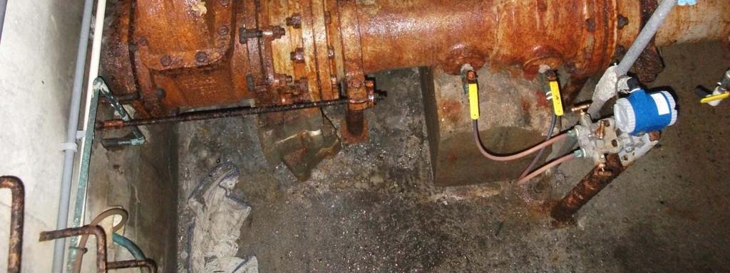
429 Lower Level Piping


430 Electrical Connection