LETTER OF TRANSMITTAL
|
|
|
- Paula Goodwin
- 5 years ago
- Views:
Transcription
1 LETTER OF TRANSMITTAL DATE: September 27, 2013 TO: Dr. Linda Hanagan Lhanagan.engr.psu.edu FROM: Alyssa Stangl ENCLOSED: AE 481W Senior Thesis Structural Technical Report 2 Dear Dr. Hanagan, This report was prepared to be submitted for Technical Report 2 for AE 481W Senior Thesis. It includes a thorough calculation and analysis of all dead and live gravity loads, wind loads, and seismic loads. The report was created using a combination of hand written calculations and excel spreadsheets. The calculations were summarized for the lateral loads in loading diagrams at the end of each section. Thank you for your time reviewing this report. I look forward to discussing it with you in the near future. Sincerely, Alyssa Michelle Stangl


2 Technical Report 2 September 27, 2013 La Jolla Commons Phase II Office Tower San Diego, California Alyssa Stangl Structural Option Advisor: Dr. Linda Hanagan
3 Technical Report 2 La Jolla Commons Phase II Officee Tower Alyssa Stangl [Structural] Table of Contents Executive Summary... 3 Site Plan and Location Abstract... 5 Documents Used to Create this Report... 6 Gravity Load Calculations... 7 Typical Roof Bay... 8 Typical Floor Bay Non Typical Floor Loads Typical Exterior Wall Wind Load Calculations Hand Calculations Excel Spreadsheet Wind Load Summary Seismic Load Calculations Hand Calculations Excel Spreadsheet Seismic Load Summary P age
4 Alyssa Stangl [Structural] Executive Summary La Jolla Commons Phase II Office Tower is a 13 story office building in San Diego, California. Each floor is about 40,320 square feet, and the structure reaches 198 feet from ground level to the top of the penthouse. With two levels of underground parking, the building extends about 20 feet below grade. Acting as an office building for LPL Financial, the building has open floor plans and large areas of glass curtain wall. La Jolla Commons Tower II received a LEED-CS Gold Certification and is the nation s largest and most advanced net-zero office building. The building s gravity system begins with a mat foundation, two stories below grade. The mat foundation was chosen for its constructability, when compared to a system of footers and grade beams. The super structure consists of two way, flat plate, concrete slabs on a rectangular column grid. A typical bay is 30 feet by 40 feet. Each level varies in thickness 18, 14, or 12 inches, reinforcing was used as required by code. Camber was used for the slab at each level (except Lower Level 2 where the mat foundation serves as the floor). This was done because large construction loads crack the slab, causing considerable deflections after construction and finishes are completed. Camber ranges from ¼ inch at the exterior edge of a bay to 2 ¼ inches at the center of the bay, creating an essentially flat slab after building loads have been applied. Laid out at the core of the building, the lateral system of La Jolla Commons Tower II consists of reinforced concrete shear walls. Due to the high shear forces associated with earthquake loading in this Seismic Category D structure, the diaphragm is not relied upon to transfer lateral loads to the shear wall system; therefore, collector beams are used to aid in load transfer. La Jolla Commons Tower II has two unique structural and architectural features. The north and south sides of the building feature 15 foot cantilevers that start at Level 3 and continue up to the roof level. The structure is similar to that of the rest of slab; however, it does have additional reinforcement and a thickened slab edge, creating a back-span for the cantilever. Also, the building has a plaza area on the Ground Level which essentially carves out a portion of the Ground Level and Level 2. Main building columns are exposed here, and additional 18 inch columns are added to support the slab edge above. La Jolla Commons Tower II was designed using the 2010 California Building Code which corresponds to ASCE 7-05 and ACI CBC 2010 and ASCE 7-05 were used to calculate live, wind, and earthquake loads. ACI , Chapter 21, references the design of concrete Earthquake-Resistant structures, and ASCE 7-05, Chapter 12, details the Seismic Design Requirements for Building Structures. Both of these documents were used heavily in the design of LJC II in order to account for seismic loading and detailing. La Jolla Commons Phase II Office Tower is full of educational value. It has several structural challenges and unique conditions punching shear, seismic loading and detailing, concrete shear wall design, and computer modeling. 3 P a g e


5 Alyssa Stangl [Structural] Building Site Information San Diego California (Google Maps) Building Site Plan (Courtesy of Hines) 4 P a g e

6 Alyssa Stangl [Structural] 5 P a g e
7 Alyssa Stangl [Structural] Documents Used to Create This Report California Building Code 2010 o Adopts IBC 2009 with some modifications American Society of Civil Engineers o ASCE 7-05 Minimum Design Loads for Buildings La Jolla Commons Phase II Office Tower o Construction Documents o Technical Specifications 6 P a g e
8 Alyssa Stangl [Structural] GRAVITY LOAD CALCULATIONS
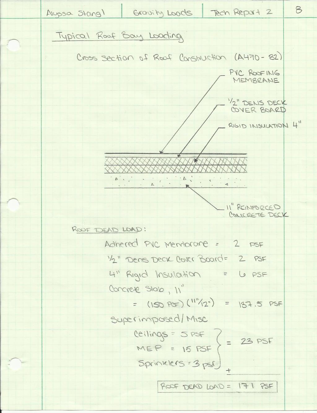
9
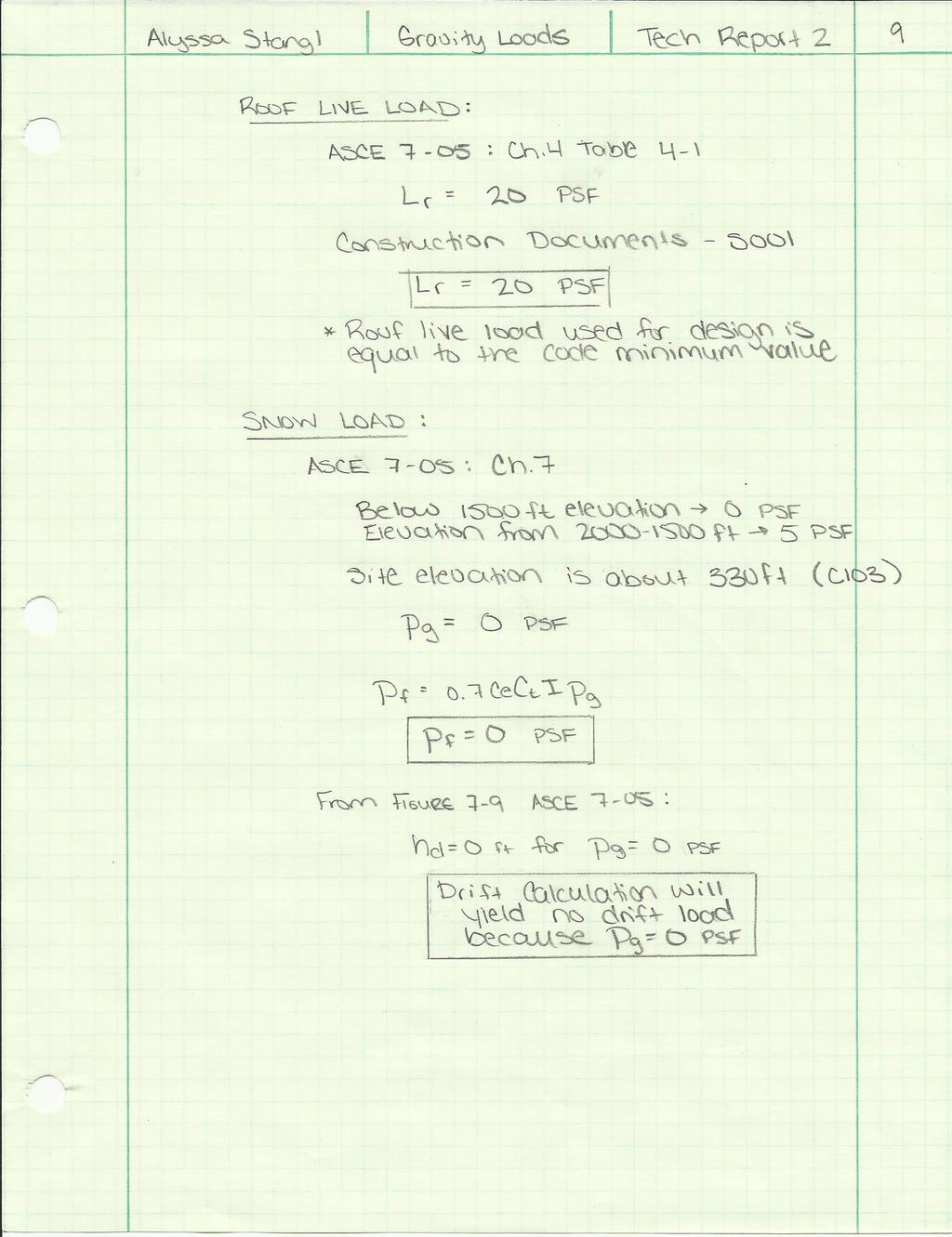
10
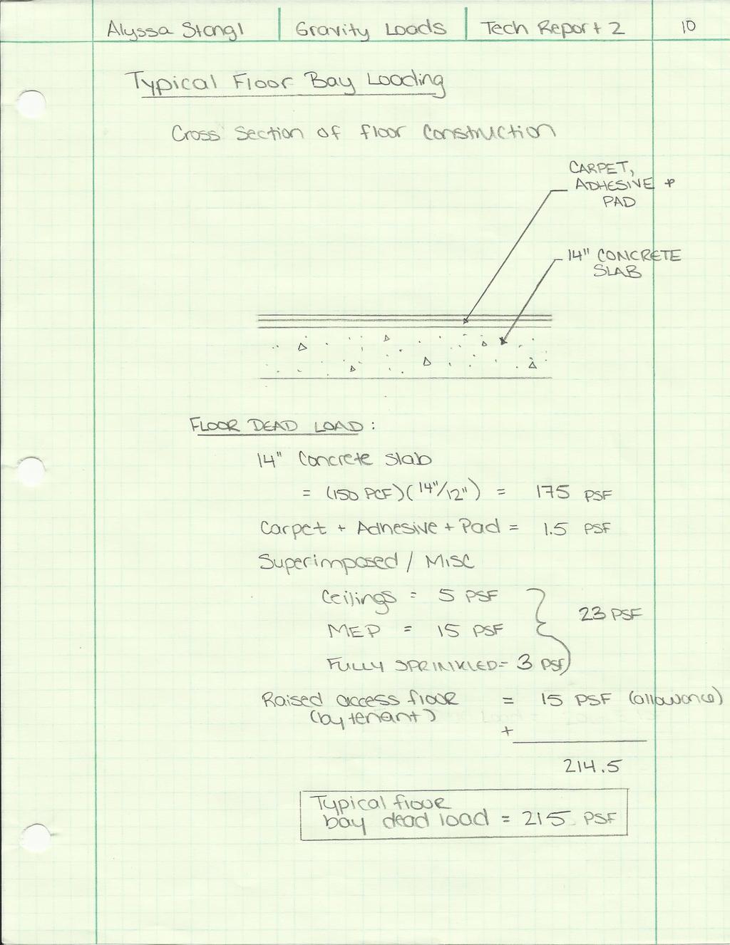
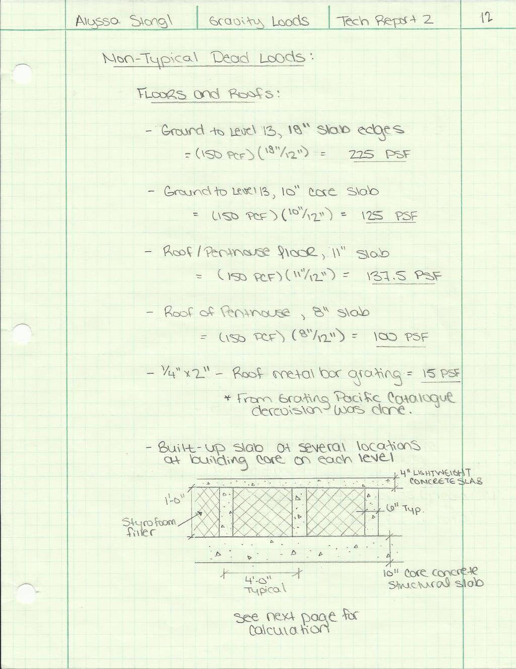
11
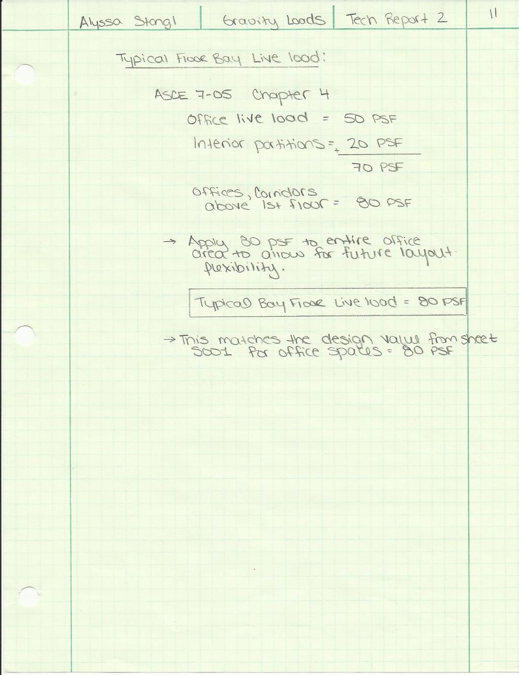
12
13

14

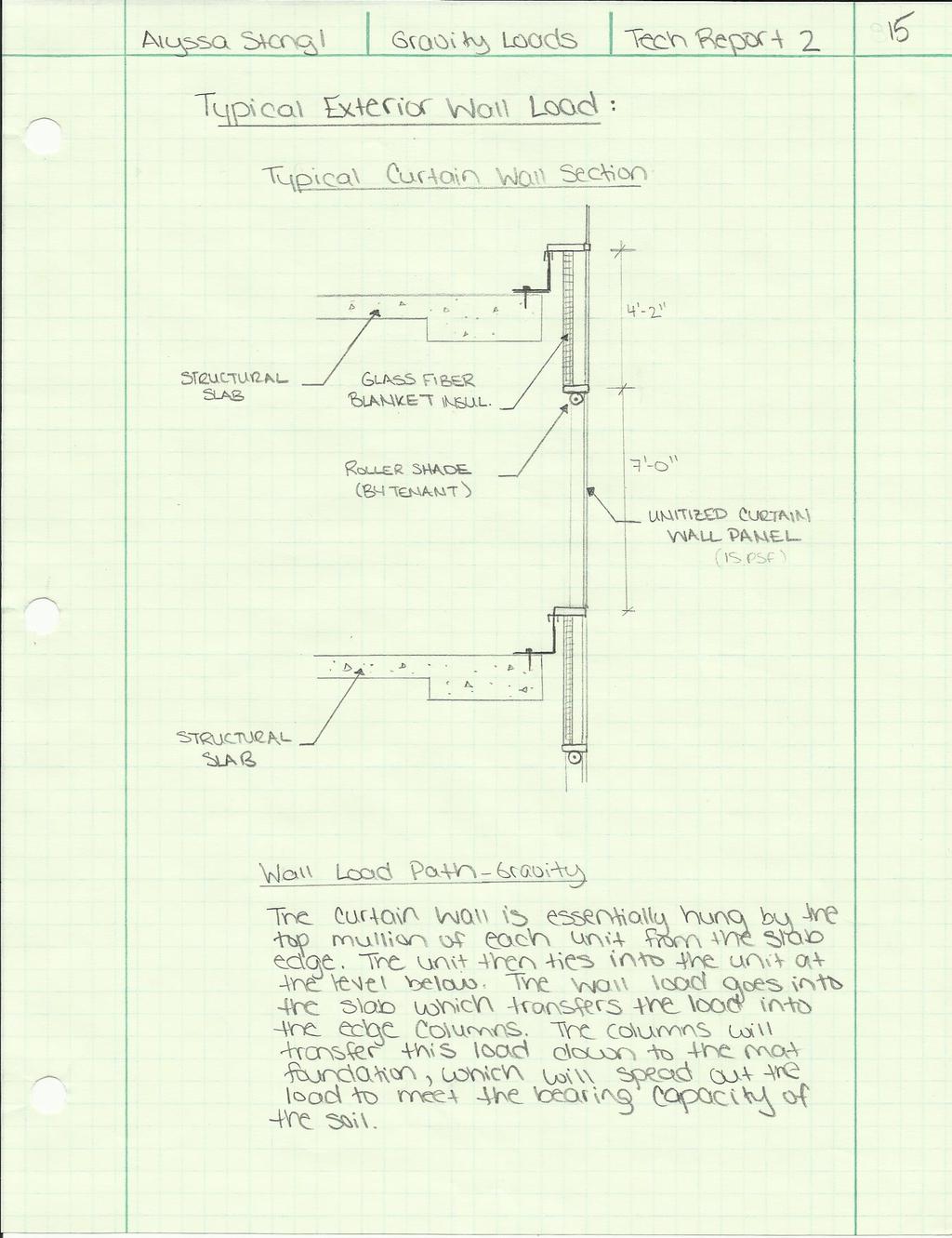
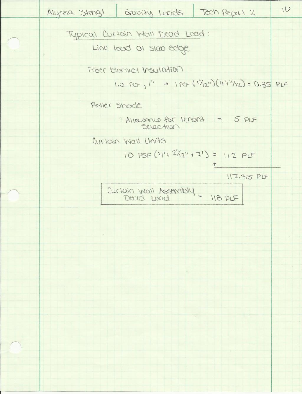
15
16
17
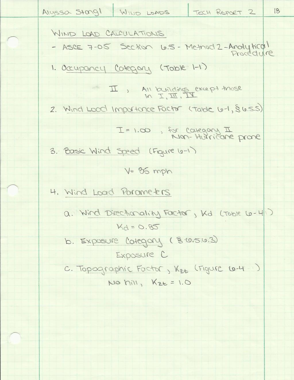
18 Alyssa Stangl [Structural] WIND LOAD CALCULATION
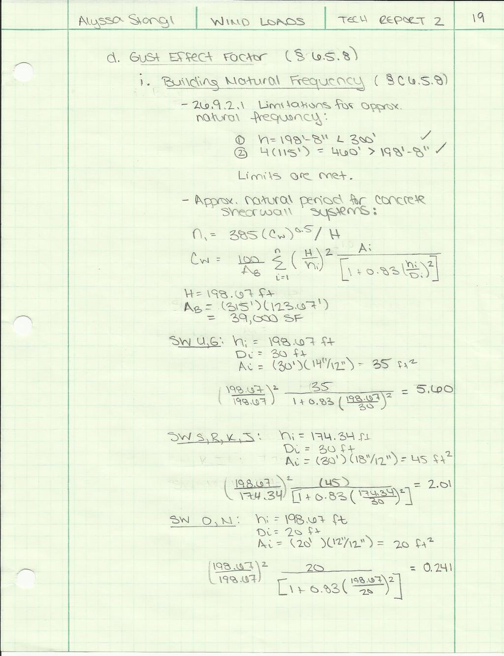
19
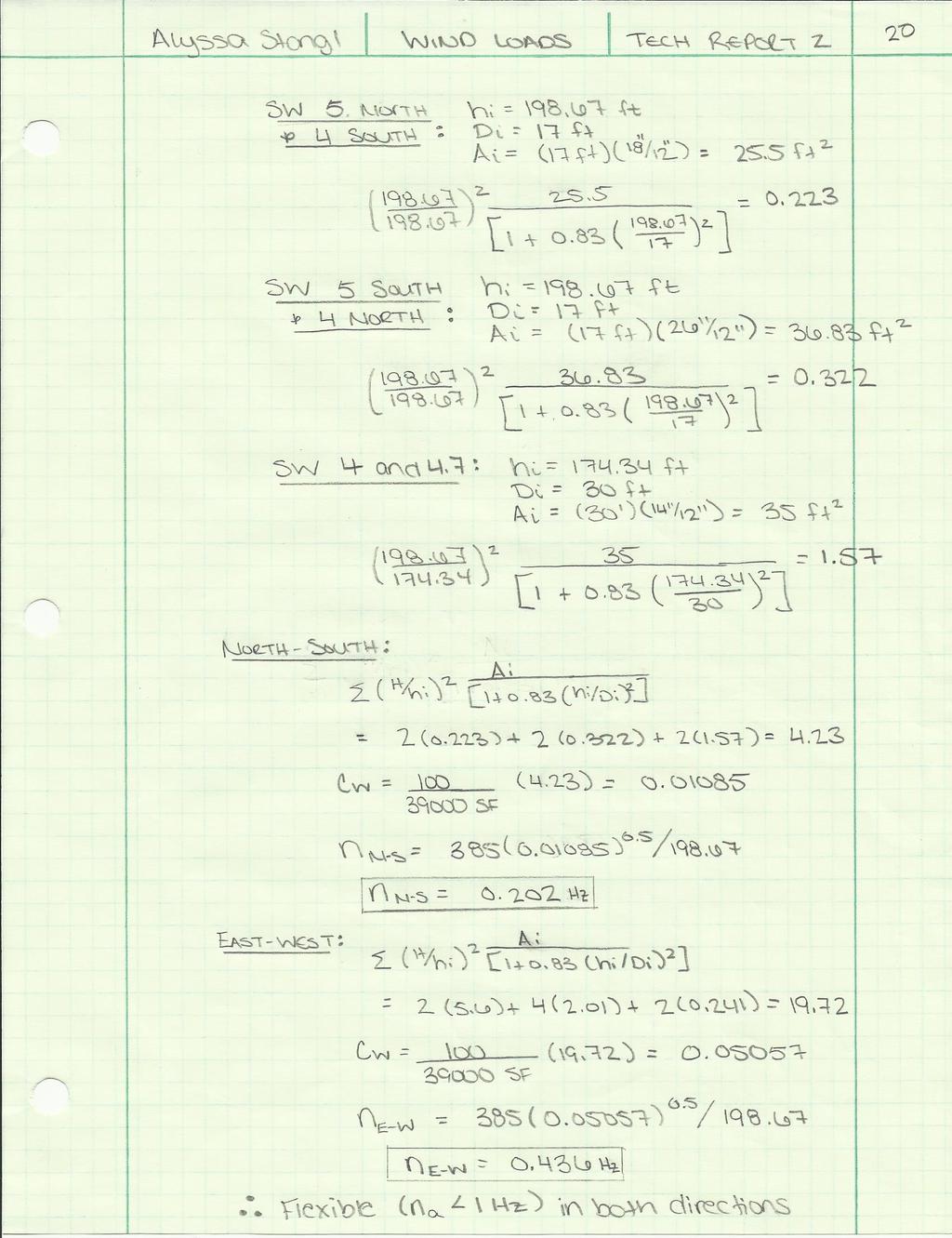
20
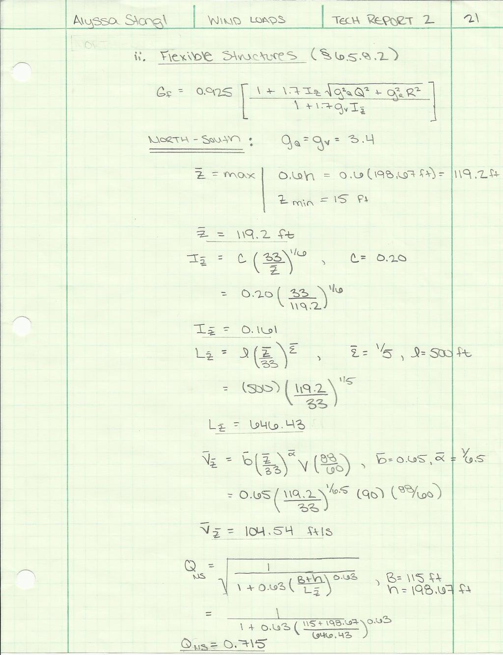
21
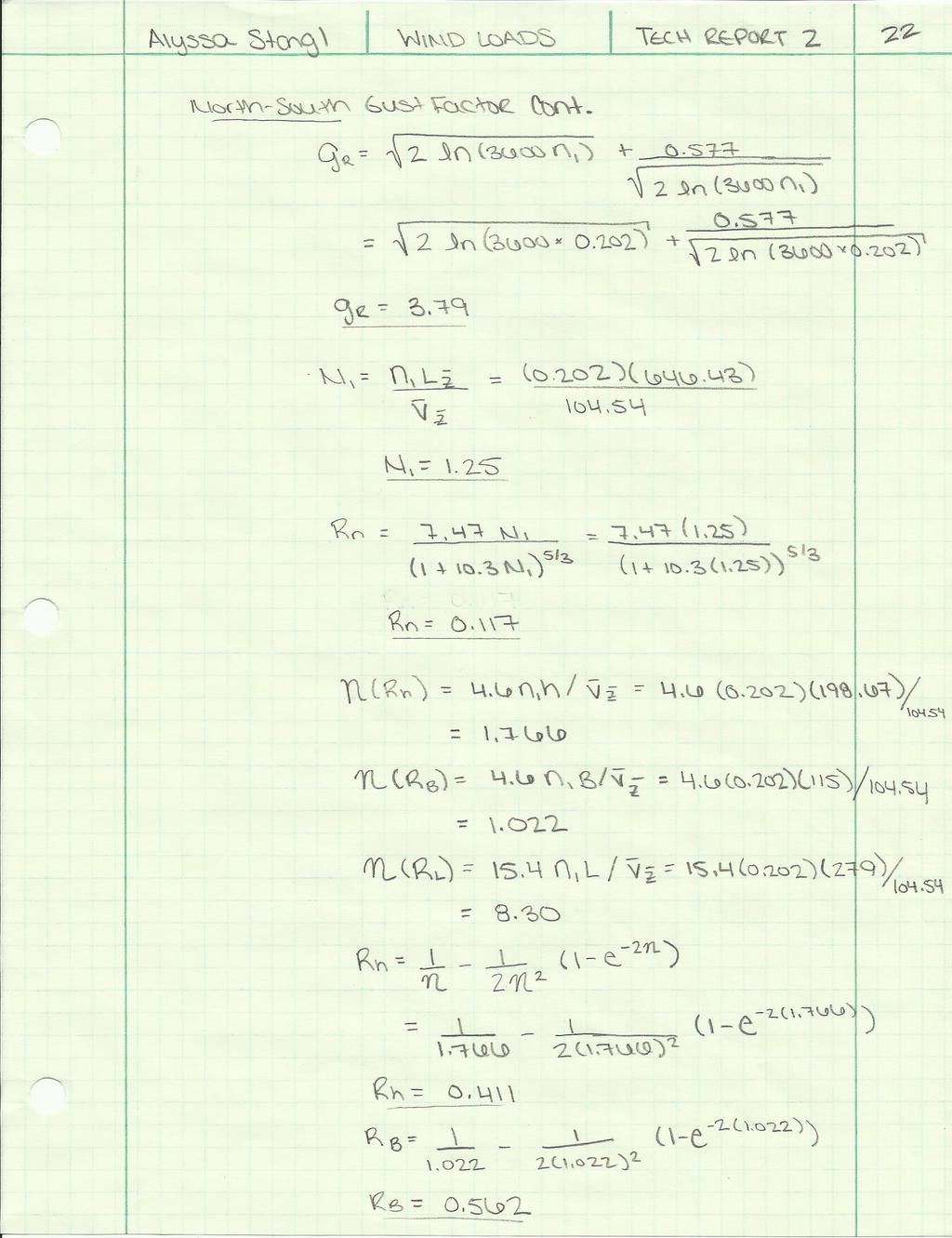
22
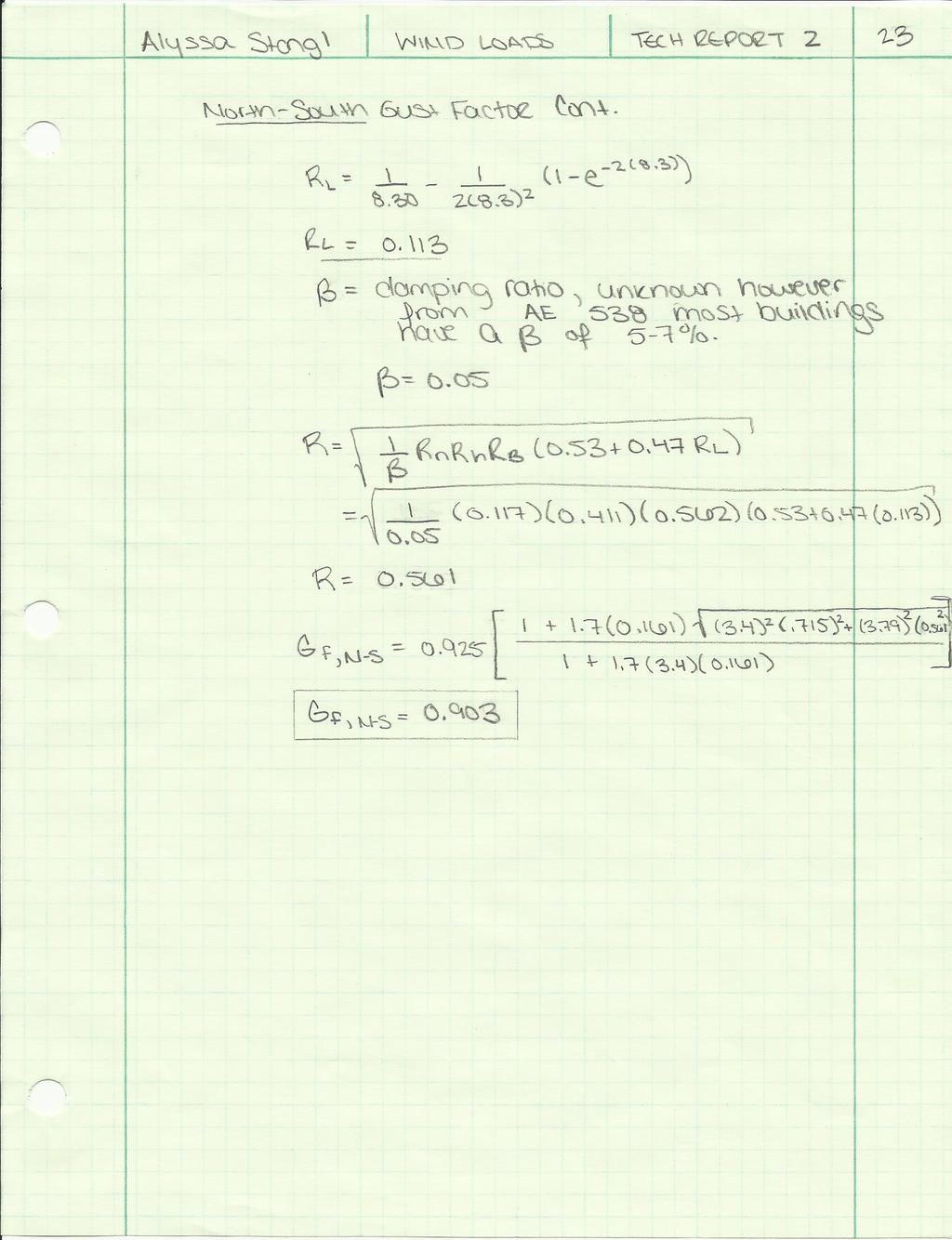
23
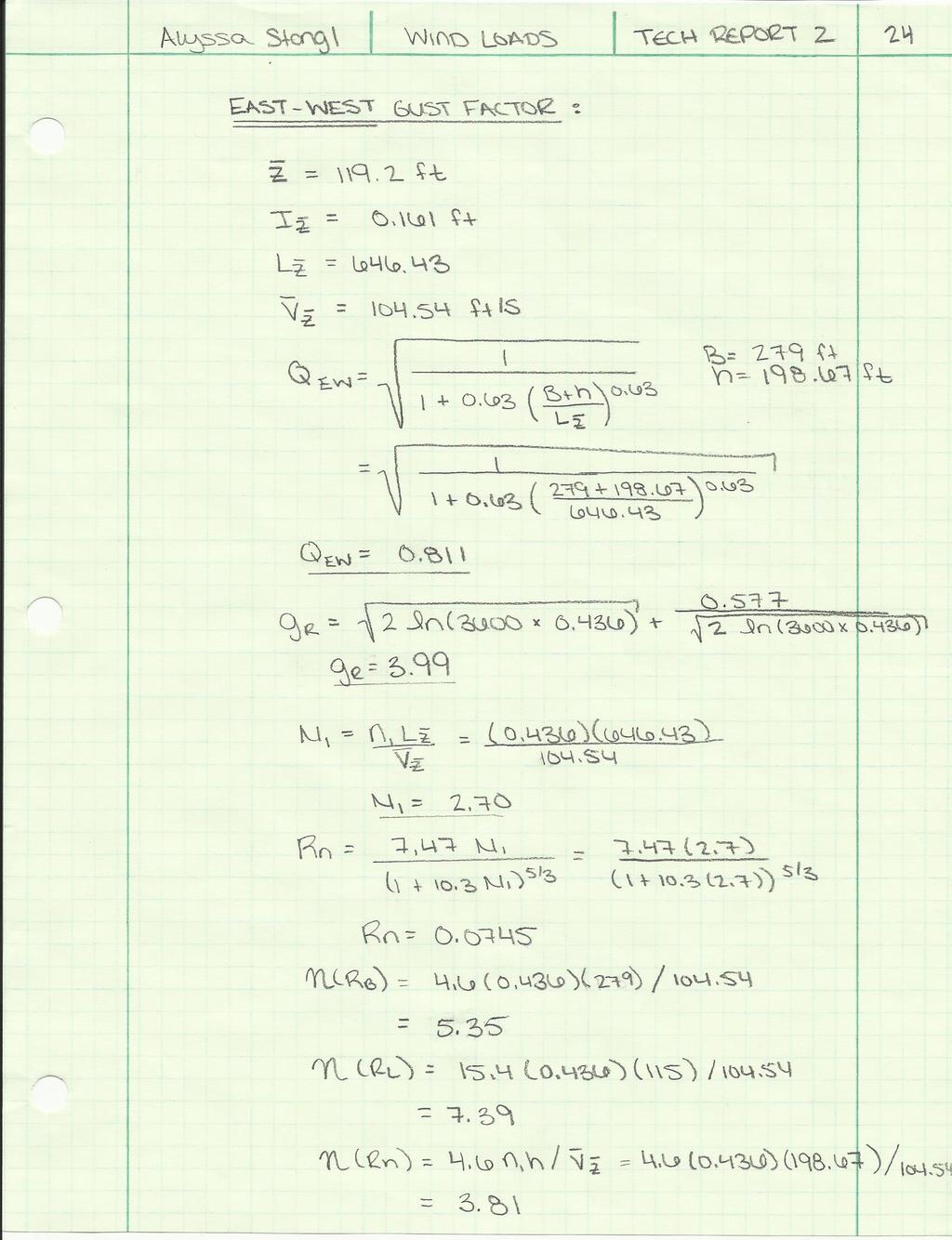
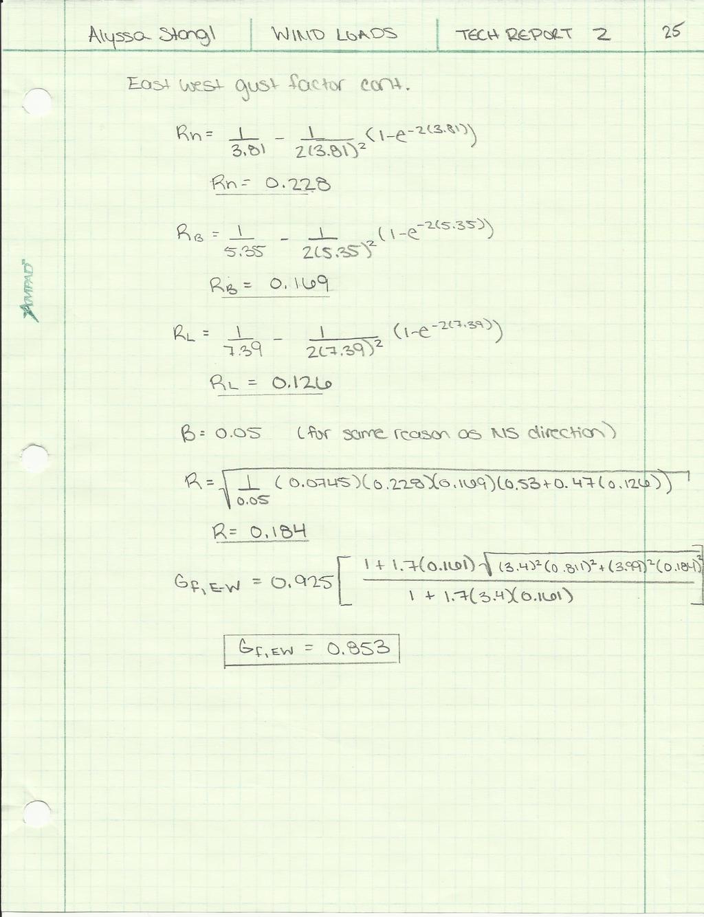
24
25
26
27
28
29 Alyssa Stangl Technical Report 2 Due: 9/27/13 WIND LOADING CALCULATIONS Equations Utilized: Constants Previously Calculated by hand: Kz = 2.01 (z/z g ) 2/α k zt = 1.00 q z = K z K zt K d V 2 I k d = 0.85 p=qg f C p (MWFRS for Flexible Buildings) V = 85.0 I = 1.00 G f, NS = G f, EW = Caclulating k z and q z NS and SW Floor Number Height above ground (z) z g α k z q z q h Penthouse Floor Penthouse Roof
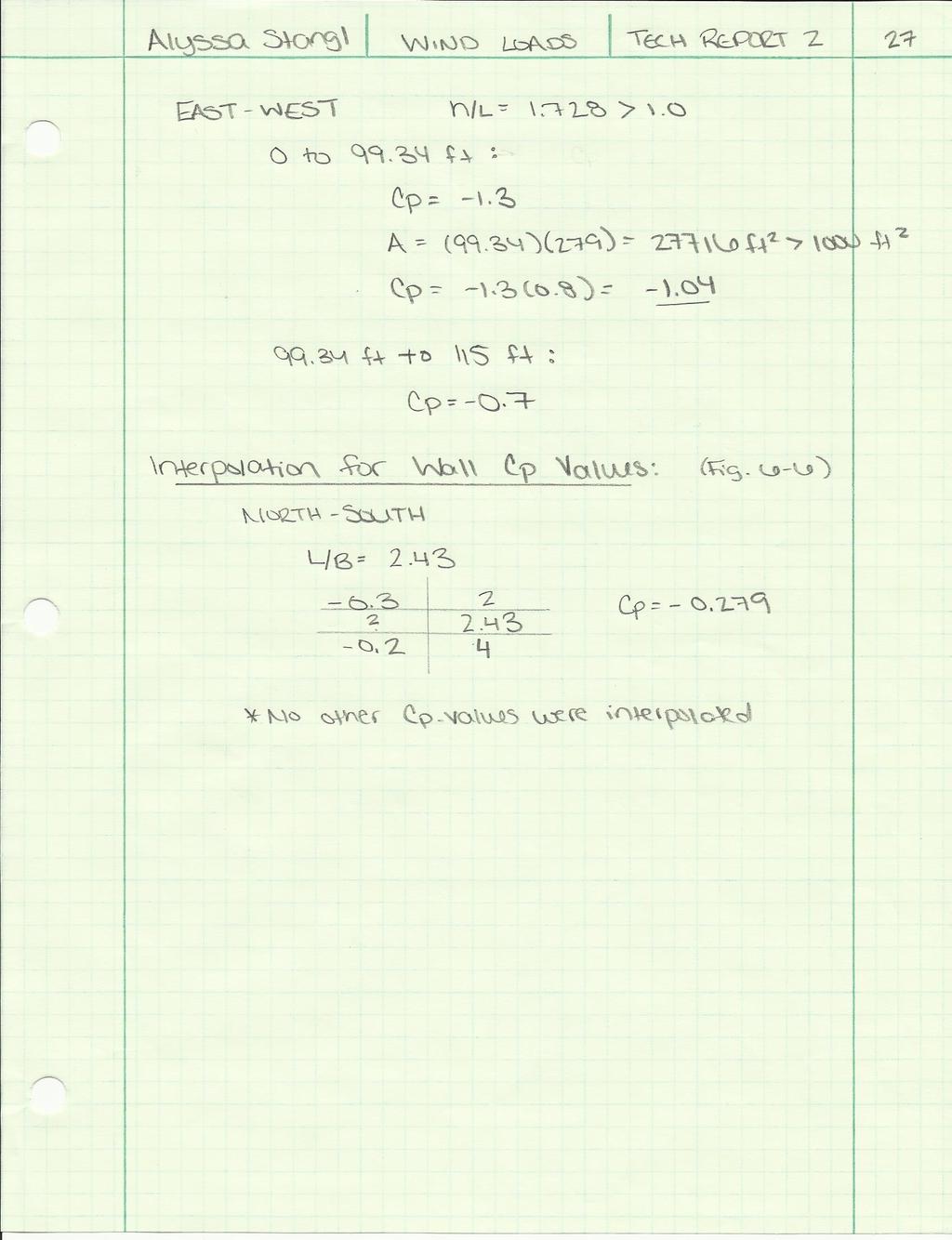
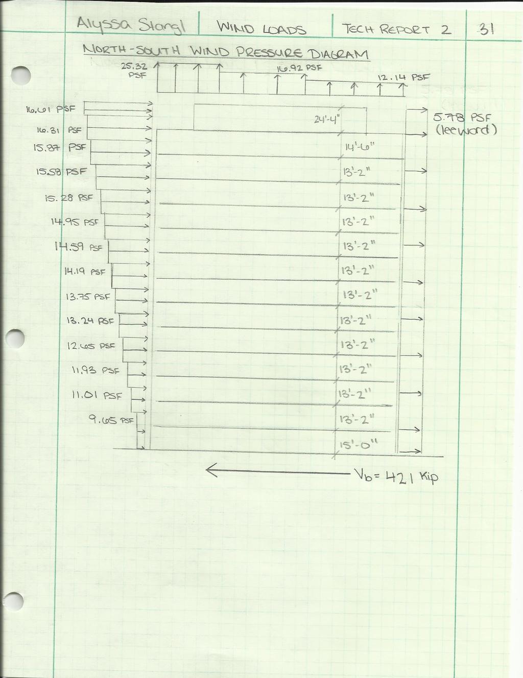
30 Wall Pressures NORTH SOUTH DIRECTION Wind Pressures North South Direction Floor Number Height above ground (z) q z q h Windward (PSF) Leeward (PSF) Trib Height Trib Area (SF) Force (k) Story Shear (K) Overturning Moment (ft k) Ground Penthouse Floor Penthouse Roof Base Shear [k] = 421 Total Overturning Moment [ft k] = Windard Wall C p = L= Leeward Wall C p = B= (interpolate) L/B= 2.43 Wall Pressures EAST WEST DIRECTION Wind Pressures East West Direction Floor Number Height above ground (z) q z q h Windward (PSF) Leeward (PSF) Trib Height Trib Area (SF) Force (k) Story Shear (K) Overturning Moment (ft k) Penthouse Floor Penthouse Roof Base Shear [k]= 1167 Total Overturning Moment [ft k] = Windard Wall C p = L= Leeward Wall C p = B=
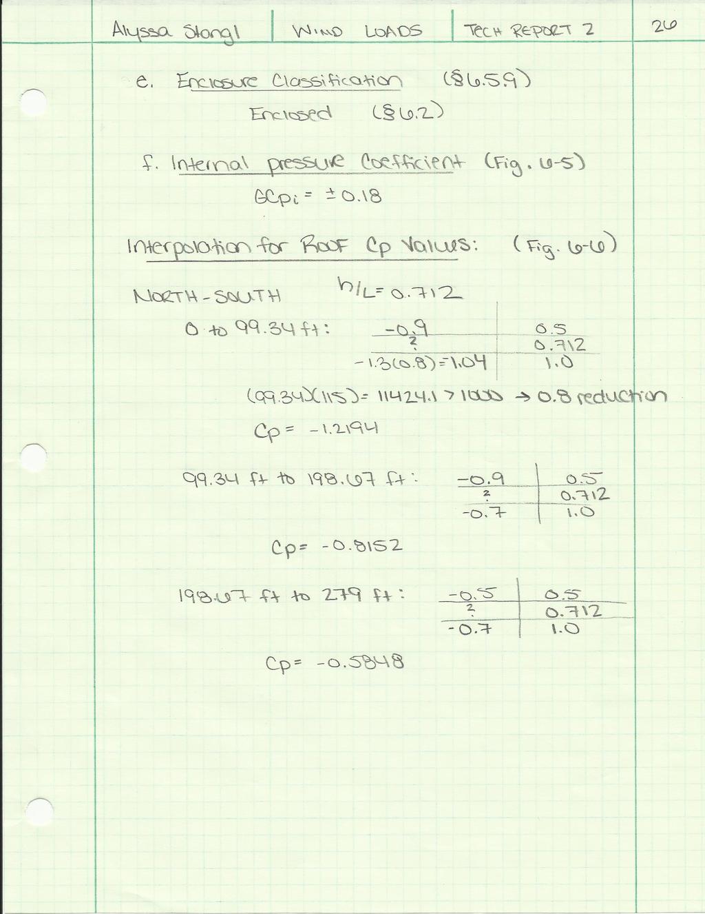
31 Wind Pressures Roof Uplift North South Location on Roof Cp G q h Pressure [PSF] 0 to ft < Area Reduction Applies for Cp = 99.34*115= ft to ft to 279 ft h= L= 279 h/l= Roof Wind Uplift NORTH SOUTH DIRECTION NOTE: Interpolation between h/l=0.5 and h/l=1.0 can be seen on Page 18 of hand calculations. Also, Area reduction calculation can be seen on Page 18. Wind Pressures Roof Uplift East West Location on Roof Cp G q h Pressure [PSF] 0 to ft: < Area Reduction Applies for Cp= 99.34*279=27716 ft to 115 ft: NOTE: Area reduction application calculation can be seen on Page 19 of hand calculations. h= L= 115 h/l= Roof Wind Uplift EAST WEST DIRECTION
32

33
34 Technical Report 2 La Jolla Commons Pha ase II Officee Tower Alyssa Stangl [Structural] SEISMIC LOAD CALCULATION
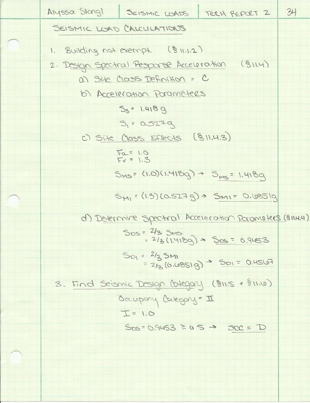
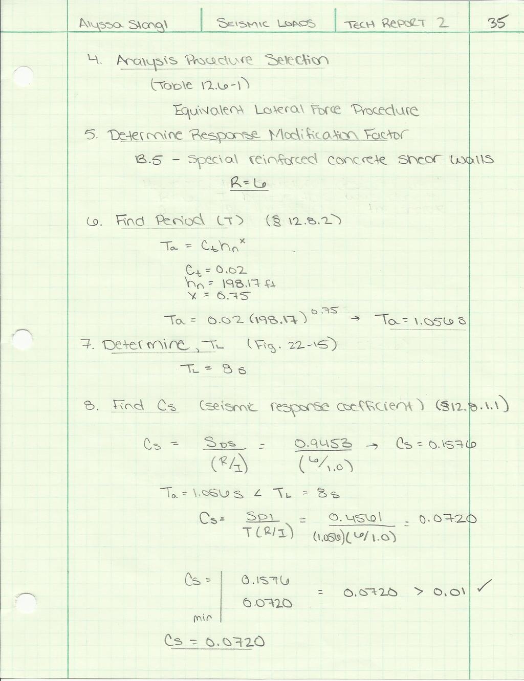
35
36
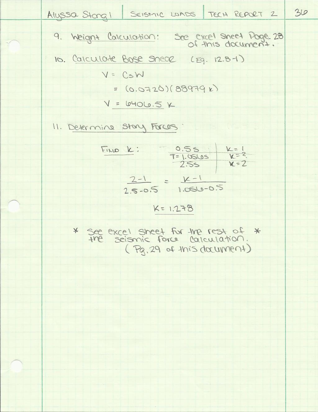
37
38 Alyssa Stangl Technical Report 2 Due: 9/27/13 SIESMIC LOAD CALCULATIONS Floor Weight Calculation Floor Number Dead Load Partition Load Total Weight (PSF) Floor Area (ft 2 ) Weight (kip) Penthouse Roof Penthouse Floor Total Weight = 88979
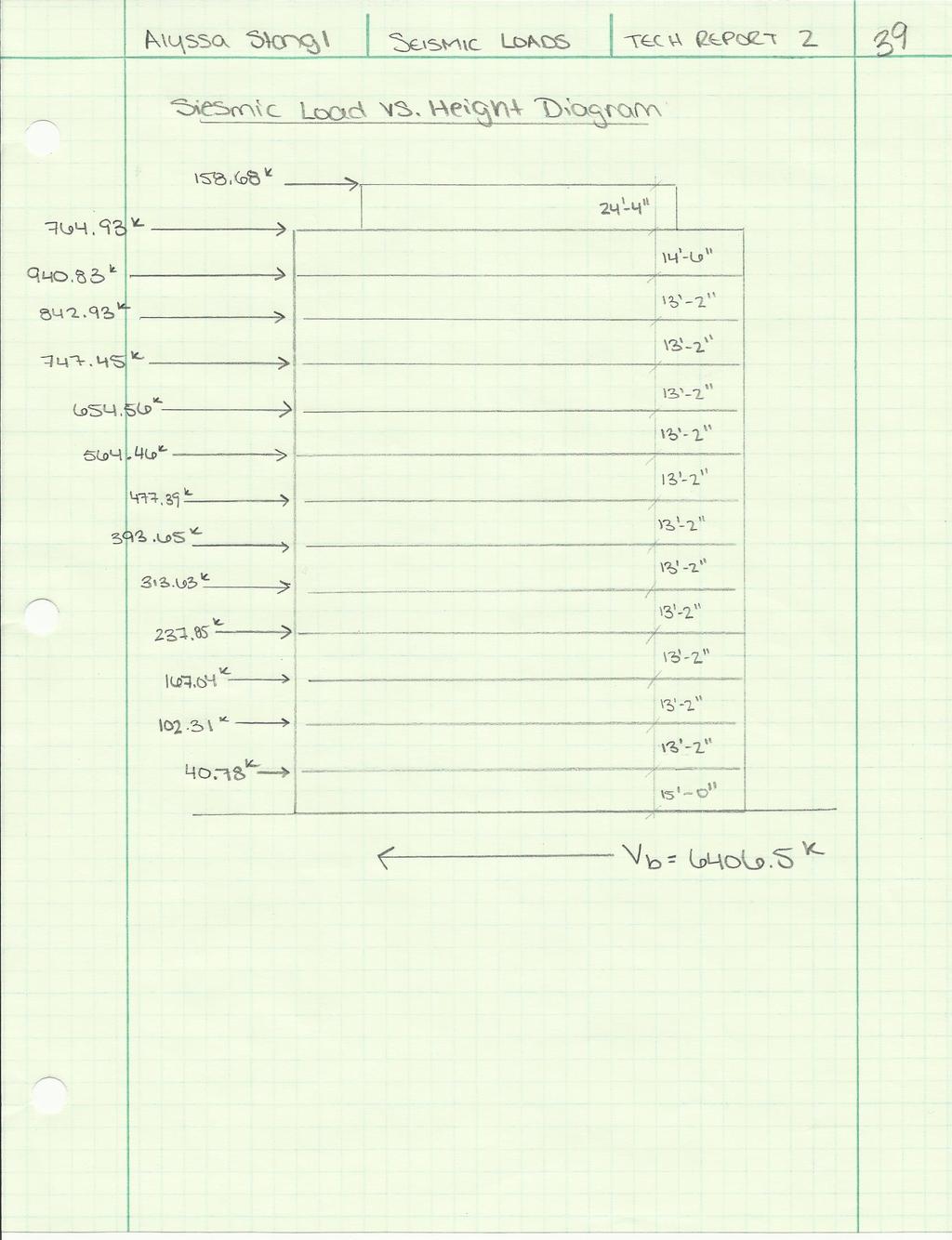
39 Seismic Story Forces T= s k= Vb= k Story Forces North South Floor Number hi (ft) h (ft) W (kip) W*h k Cvx Story Forces Fi (kip) Penthouse Roof Penthouse Floor SUM: Base Shear [k] =
40