MIDAS Structure Training Series SUBSTRUCTURE ANALYSIS
|
|
|
- Clarissa Garrett
- 5 years ago
- Views:
Transcription
1 MIDAS Structure Training Series SUBSTRUCTURE ANALYSIS


2 ANGEL F. MARTINEZ CIVIL ENGINEER MIDASOFT SUBSTRUCTURE ANALYSIS
3 CONTENTS 1. FOOTING DESIGN 2. PILE RAFT ANALYSIS & DESIGN 3. BASEMENT WALL ANALYSIS & DESIGN
4 FOOTING DESIGN

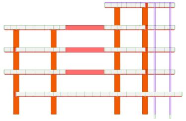
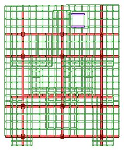
5 Dimensions 18m 21m 14m 2.8m 18m 14m 21m


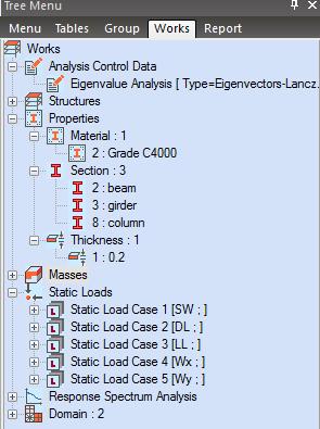
6 Inspect Properties Material -Concrete ASTM C rectangle Sections H B Column 0.45 m 0.6 m Beam 0.4 m 0.35 m Girder 0.3 m 0.2 m 1 thickness Wall Thickness 0.2 m

7 Start file


8 Boundary Conditions Assign fixed all SUPPORTS to bottom nodes (footing)

9 Perform Analysis
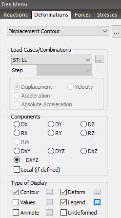
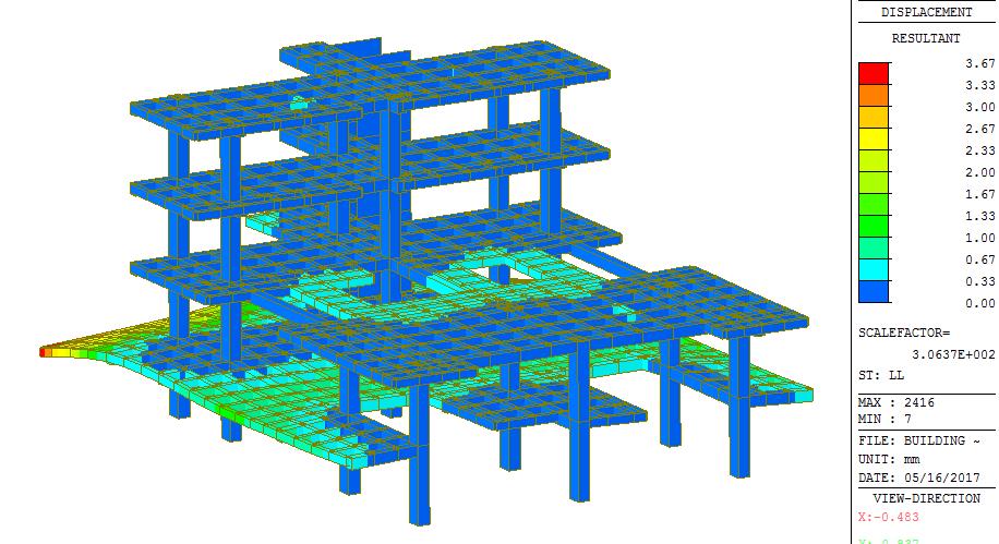
10 Results: Displacements

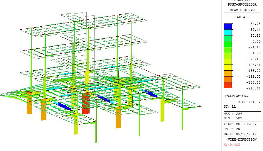
11 Results: Axial Forces

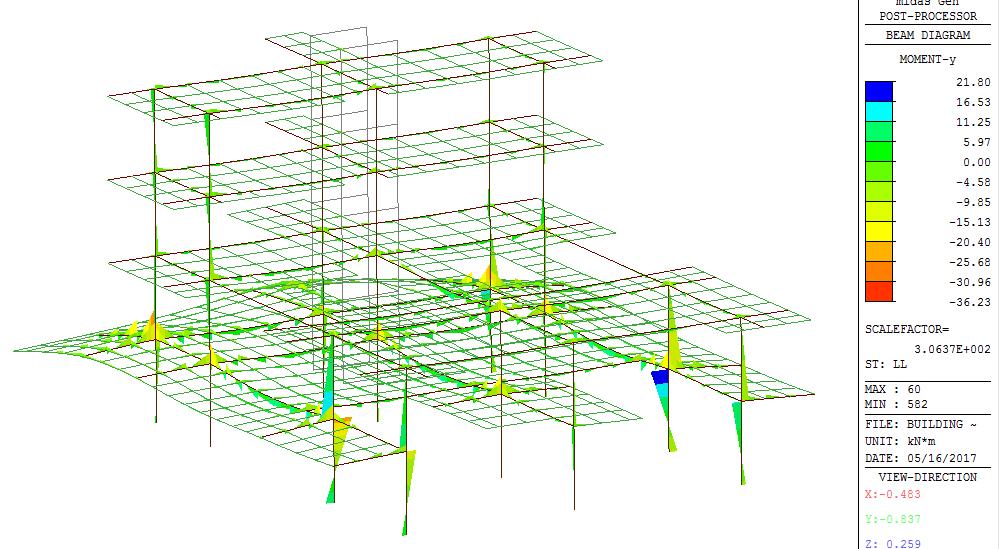
12 Results: Moments Y

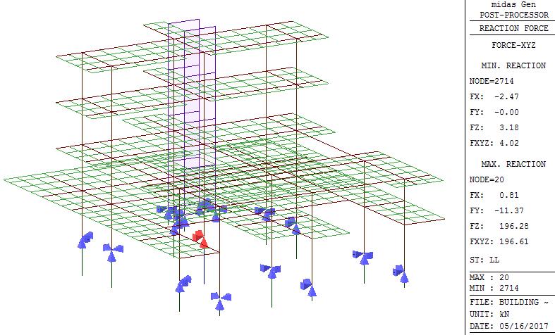
13 Results: Reactions
14 Load combination Generate Load Combo Results > Combinations > Concrete Design > Auto Generation Select Concrete Design and Footing Design Auto Generation Design Code: ACI for both


15 Footing Design: CODE CHECK Select Node 20 Enter size 1.5X1.5X.35m Enter allowable soil pressure : 300 kn/m^2 Rebar size #4 in X and Y Surcharge Load 50 kn/m^2 CODE CHECK
16 Footing Design: CODE CHECK CODE CHECK 1.5mX1.5mX0.35m

17 Footing Design: AUTO DESIGN Select Node 20 AUTODESIGN
18 Footing Design: AUTO DESIGN AUTO DESIGN 2.3mX2.3mX0.4m
19 PILE RAFT ANALYSIS & DESIGN
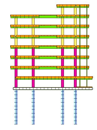

20 Dimensions 18m 2.8m 22m 20m 10m

21 Inspect Properties Material -Concrete ASTM C rectangle Sections C30X m 0.7 m V35X m 0.5 m B20X m 0.5 m N10X m 0.25 m Pile H D = 0.5 m C45X m 0.7 m B 2 thickness Wall Raft Thickness 0.2 m 0.3 m

22 Start file

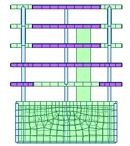
23 Extrude Piles Select column nodes to extrude piles Select pile Section Extrude -1m in dz 10 times

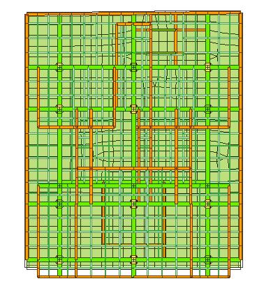
24 Auto-Mesh Slab Select beams on the base by line elements Mesh size 1m Thickness 0.3 m


25 Boundary Conditions Select Pile Spring Supports and apply to piles Soil Type: Sand Ground Level: 0m Unit weight: 2 tonf/m^3 Ko: 0.4 Kh: 800 tonf/m^3 Friction Angle: 30 deg K1: Dense


26 Boundary Conditions Select Surface Springs and apply to raft Point Spring Kx: 80 tons/m^3 Ky: 80 tons/m^3 Kz: 800 tons/m^3

27 Perform Analysis
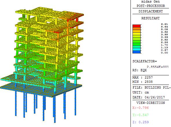
28 Results: Displacements

29 Results: Axial Forces

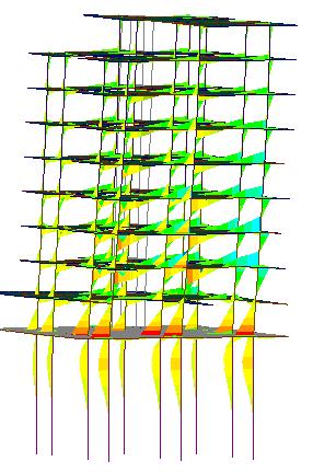
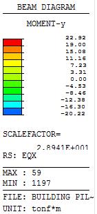
30 Results: Moments Y
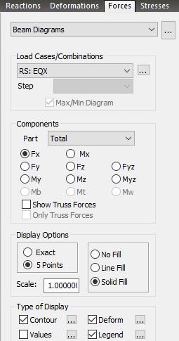
31 Load combination Generate Load Combo Results > Combinations > Concrete Design > Auto Generation Select Concrete Design Auto Generation Design Code: ACI318-14


32 Pile: Rebar Data Select Piles RC Design > Modify Column Rebar Main #4 Ties/Spirals Add / Replace

33 Select All Piles RC Design Concrete Code Check Column Check Pile: Code Check


34 1 member is NG: NOT GOOD Click GRAPHIC to see PM Curve and details Pile: Code Check
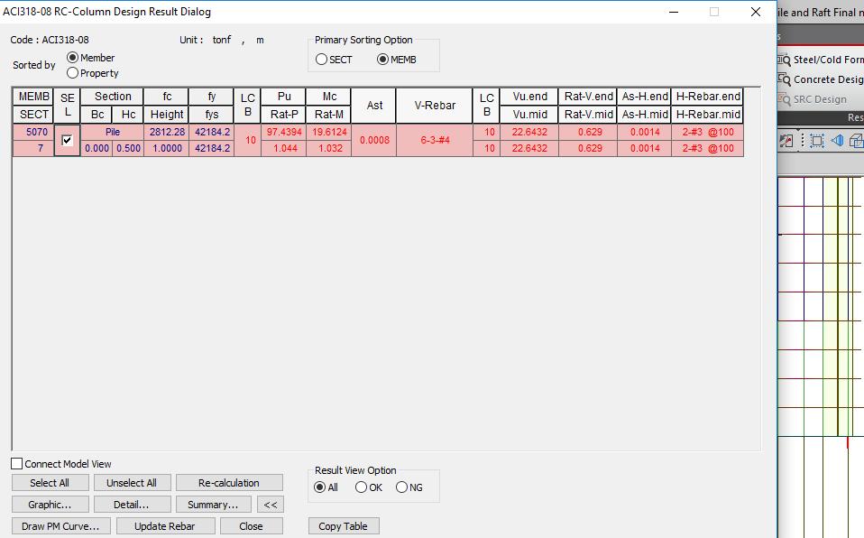
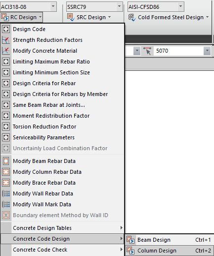
35 Run Pile/Column Design Pile: Code Design


36 Pile: Code Design 1. Click Re-Calculation Pile rebar was redesigned based on code 2. Click Update Rebar to see new rebar data created for pile
37 BASEMENT WALL ANALYSIS & DESIGN
38 Dimensions 20m 171 ft 20m 14 m 19.6 m 5.6m

39 Inspect Properties Material -Concrete ASTM C rectangle Sections H B V35X m 0.5 m B20X m 0.5 m N10X m 0.25 m C45X m 0.7 m 2 thickness Slab and Wall Basement Wall Thickness 0.2 m 0.3 m

40 Start file


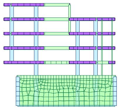
41 Extrude Piles Select column and slab corner nodes to extrude Select C45x70 Section Extrude -2.8m in dz 2 times


42 Auto-Mesh Basement Walls Select node method: Draw rectangle by clicking 4 corners of side CCW Mesh size 1m Thickness 0.2 m

43 Auto-Mesh Basement Walls Draw rectangle by clicking 4 corners of remainnig sides Mesh size 1m Thickness 0.2 m


44 Auto-Mesh Slab Select 4 corner nodes of base as shown Mesh size 1m Thickness 0.3 m


45 Boundary Condition Add Spring Supports Element Type: Planar Spring Type: Linear Kx = Ky = 80 Kz = 800 ton/m^3 Select bottom raft


46 Boundary Condition Element Type: Planar Spring Type: Compression Only Direction: Normal + K = 800 ton/m^3 Select basement walls in sequence
47 Basement Loads


48 Basement Loads Apply Hydrostatic Pressure Load Case: Water pressure load Select Basement walls -1000kgf/m^3
49 Lateral soil pressure with or without ground water pressure can be applied using this functionality. Note When lateral soil pressure is entered as Hydrostatic Pressure Loads, Element Type must be Plate, and the structure must be divided into a reasonable number of elements to properly reflect its flexural behavior. Direction represents the direction of acting force. Gradient Direction is generally selected in the direction of gravity (Global-Z). Constant Intensity (Po) represents surcharge (soil overburden), which is subject to soil pressure coefficient. Gradient Intensity (g) is also obtained by applying the soil pressure coefficient. Depending on the presence of ground water, the following is entered: Sand with gravel, 1650 (kg/m dry 3 ) 1) Only soil is present without ground water Sand with gravel, Soil: g = soil pressure coefficient * unit density of soil 2020 (kg/m wet 3 ) Earth Pressure Co 2) To consider ground water (separately enter values for soil and water) 1 efficient Soil: g = soil pressure coefficient * unit density of soil under water Water: g = unit density of water Surcharge Po 600 (kg/m^3) (In case of water, Reference level (H) locates the level of ground water.)


50 Basement Loads Apply Hydrostatic Pressure Load Case: earth pressure Select Basement walls -600 kgf/m^2 constant intensity kgf/m^3 gradient intensity


51 Load combination Generate Load Combo Results > Combinations > Concrete Design > Auto Generation Select Concrete and Design Auto Generation Design Code: ACI318-14

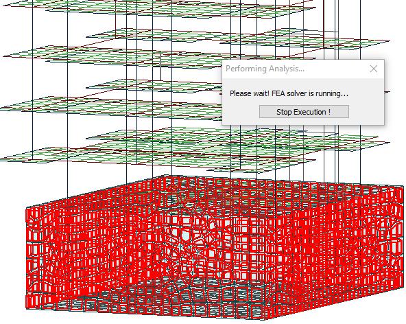
52 Perform Analysis
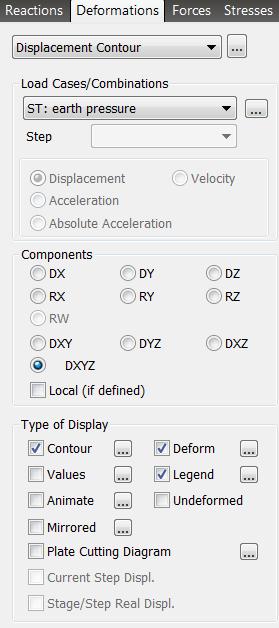

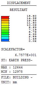
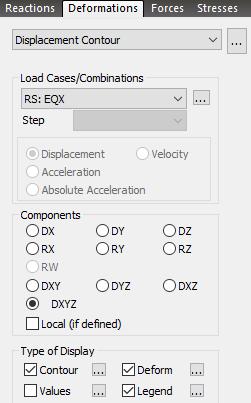
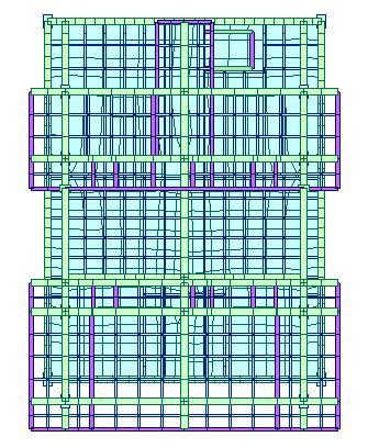
53 Results: Deformations Check Deformations


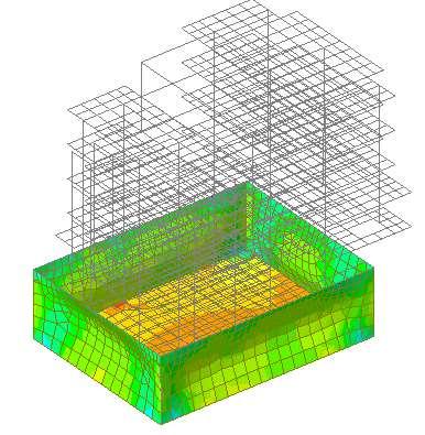
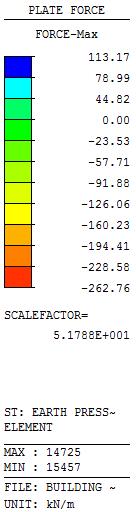
54 Results: Axial Plate Forces Check Axial Forces


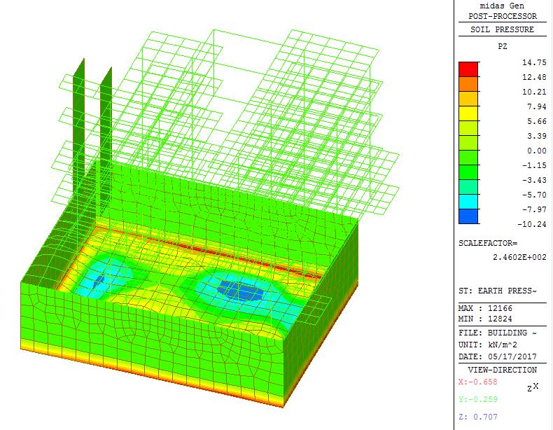
55 Results: Soil Pressure Check Vertical Soil Pressure


56 Slab and wall load combinations Slab/Wall Load Combination Select the load combinations for the slab/wall element design. Design > Design > Meshed Design > Slab/Wall Load Combinations


57 Define Design Criteria for Rebar Specify rebar size Enter the standard sizes of rebars used in the design of reinforcement for slab/wall elements. Design > Design > Meshed Design > Design Criteria for Rebar Check off [Basic Rebar for Slab] For Slab Design: Dir. 1 : 0.03 m, 0.03 m Dir. 2 : 0.05 m, 0.05 m For Wall Design Face to Center Rebar 0.02m v


58 Slab/Wall Rebar Checking Data Specify rebar size Select all 0.3m slab from tree menu Layer Top Dir 1 Add Rebar 1: 100 Add Rebar 2 #3 Add/Replace


59 Slab/Wall Rebar Checking Data Specify rebar size Select all 0.2m walls from tree menu Layer Top Dir 1 Vertical 1: 100mm Horizontal 2: 100mm Add/Replace


60 Slab Flexural Design Run Design Select Avg. Nodal Dir Select Rebar Ratio > Apply 2. Click: Update rebar


61 Slab/Wall Rebar Checking Data Rebar Update New sets of reinforcement were automatically created for parts of slab


62 Wall Design Run Design Specify Design Criteria 1. Select Rebar Ratio > Apply 2. Click: Update rebar