Report Date: 03/11/2010
|
|
|
- Elizabeth Ross
- 5 years ago
- Views:
Transcription


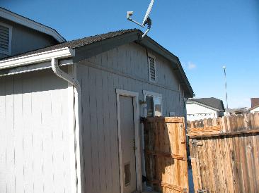
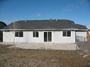
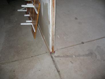
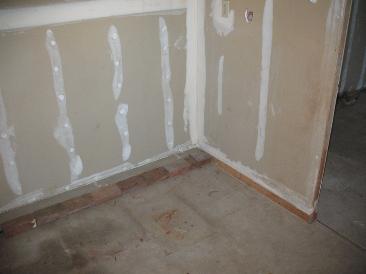
1 KIRK N. ELLIS & ASSOCIATES STRUCTURAL & CIVIL ENGINEERING, LTD. 245 East Liberty Street, Suite #425 Reno, Nevada Phone: (775) Fax: (775) TO: Mr. Tim O'Fallon Reno Housing Authority 1525 East Ninth Street Reno, NV DATE: 03/10/2010 JOB #: 0810 PROJECT: RHA Residential Inspection LOCATION: 9930 Crystalline Court CONTRACTOR: N/A OWNER: Reno Housing Authority WEATHER: Scattered Clouds TEMP: 31 F TIME: 9:00AM PRESENT AT SITE: Brian Wilcox Kirk N. Ellis & Associates Kirk N. Ellis Kirk N. Ellis & Associates Report Date: 03/11/2010 At the request of Tim O'Fallon of the Reno Housing Authority, this office went to conduct an Initial Structural Engineering Visual Inspection Site Visit for the residence located at 9930 Crystalline Court. This residence is identified by the Washoe County Assessor as APN: , and listed as a Single Story, Single Family Residence built about The following was noted: 1. The exterior is composed of a combination of horizontal lap siding and T-111. See Figure 1. There are several locations on the T-111 siding where the edge nailing as elongated the holes to the point of failure. See Figure 2. FIG 1: EXTERIOR 2. The interior of the residence appeared to have a relatively new coat of interior paint. Only one location of cracked gypsum was observed at the front room dropped ceiling. No compression bulges or tension cracks were observed in the gypsum board finishes. 3. All interior and exterior doors and exterior windows were opened. All openings were freely operated and showed no signs of racked openings. Failed Nails FIG 2: FAILED SHEATHING NAILS. 4. All interior surfaces (gypsum board walls, gypsum board ceilings, finish floors) appeared nominally true to a reasonably flat plane. No objectionable or noticeable bulges, cracks, etc. were seen. 5. This structure is constructed directly on the surface of a concrete slab-on-grade. No cracks or elevation differentials were felt or observed in the interior slab. Exterior inspection of concrete revealed general separation of the slab and footing. See Figure 3. This is a very poor quality


2 RHA Residential Inspection 03/11/ Crystalline Court Page 2 of 5 cold joint on the (2) pour slab/grade beam system. It is not known if a rebar slab dowel ties the pours together. Most, if not all, of the holdown straps have blown through the exterior face of the footing and slab or exhibit a general lack of concrete vibration/consolidation in from of the strap embedment. See Figure All areas accessible from the attic access point and above the insulation were inspected. There is a large platform in the attic area above the garage. See Figure 5. The roof truss chords and webs did have drying splits, but no stress fractures were observed. See Figure 6. No water damage was observed. There were several location of continuous lateral bracing, however, some bracing had been cut for access to the makeshift attic storage area. The exterior gable end walls did not appear to have sheathing. One of the structural gable ends had webs cut to make room for gable end vents. See Figure The garage slab exhibited no buckling or excessive cracking. Most of the slab cracking was controlled through crack control joints installed in the slab. The minor cracks in the garage slab are typical and of no structural concern. There is an owner-built 4x2 wall separating the garage. 8. The mechanical equipment, in both the garage and the attic, appear to be seismically braced. Seismic strapping is present. FIG 3: SEPARATION OF CONCRETE SLAB AND SUPPORTING FOUNDATION FIG 4: SIMPSON HOLDOWN HAS BLOWN THROUGH EXTERIOR FACE OF CONCRETE FOOTING AND SLAB FIG 5: MAKESHIFT ATTIC STORAGE FIG 6: TOP CHORD DRYING SPLIT FIG 7: WEBS OF GABLE END CUT TO ALLOW FOR INSTALLATION OF VENTS. F I E L D R E P O R T Field Report Crystalline Court.docx
3 RHA Residential Inspection 03/11/ Crystalline Court Page 3 of 5 KNE Discussion Based on what was visually seen at the time of inspection, the current as-built/existing structural systems for this residence present some serious concerns. Please note that this was a visual inspection only. No destructive testing or structural calculations were done, no thermal insulation or finish work was removed. There are several indicators that we look for as a marker of structural failure or movement. As a structure bends and flexes under the strain of lateral forces (wind or seismic) there tends to be a racking or twisting movement. This can be seen in the frames of doors and windows. The racking or twisting of the openings changes the shape from a rectangle to a parallelogram. The shape shifting causes doors to not fit correctly in the frames and windows become difficult to operate. The sheet rock also shows these stresses at the corners in the form of compression bulges or diagonal tension cracks. If excessive and repetitive movements have occurred, the finish exterior can show signs of stress as well. No such movement racking was seen. The residence showed no evidence of stiff or racked door openings or stiff or racked window openings. No compression bulges were visible and the only crack seemed to be non-structural. The cracks are probably just due to normal lumber drying shrinkage. With no additional cracking and no other racked openings the signs of movement appear to be localized. The exterior horizontal lap siding showed no signs of buckling, and the edge and field nailing showed no signs of elongating. This type of siding is extremely forgiving and can conceal defects and movement. The T-111 siding had edge nailing that has elongated to the extent of failure. This is a clear indication of structural movement. The siding should be removed and the structure inspected further. Vertical/gravity load effects are typically not seen when adequately designed. Failures can usually be seen with flexural fractures and eccentricities in the structural members. Excessive deflection can also be an indication of poor construction or inadequately calculated structural members. No stress fractures were observed in the roof trusses affected by the make-shift attic storage area. Premanufactured wood roof trusses are generally designed for minimum loads. Rarely, if ever, do these loads include attic storage. Tract housing trusses usually optimized for the minimum amount of lumber and steel plates. The trusses at this residence have been optimized so far that they have even reduced the webs to 2x3 members. These trusses are probably NOT designed for attic storage loads. The residence appeared to have relatively straight and plumb interior surfaces, and the lower slab and upper floor systems appeared to be sturdy and did not excessively deflect. The lower slab showed no signs of elevation change or cracking. The finish flooring would probably hide most flaws. Inspection of the exterior area of the slabs revealed no excessive cracking. All areas of the attic area that were accessible for inspection revealed no stress fractures or failures. The wall studs and columns were not available for inspection. No insulation or finishes were removed for inspection. As a concrete slab or footing cures, it experiences many thermal and drying shrinkage variances. The expansion and contraction of the concrete slab normally causes hairline fractures in the concrete. The reinforcing in concrete slab and footings exists to preclude complete fracture of the footings and stem walls, so it can retain it's structural strength. Typically, temperature cracks do not exceed 1/32 F I E L D R E P O R T Field Report Crystalline Court.docx
4 RHA Residential Inspection 03/11/ Crystalline Court Page 4 of 5 and occur approximately every six to eight feet. These cracks propagate perpendicular to the length of the stem wall (shortest distance). No unusual concrete cracks were seen. On the other hand, differential settlement or foundation movement cracks typically radiate 45 from point of maximum load, or 45 perpendicular to the length of the footing or stem wall. None of this type of crack was seen. The concrete footing and slab were not open for inspection. The exterior face of the footings was visible for the top 6-inches. The concrete slab has begun separating from the footing. Shear wall holdowns that are embedded in the concrete stem wall and footing are breaking through the exterior face of the concrete. The as-built/effectiveness of the holdown straps is questionable at best. A retrofit holdown should be engineered and details drawn. The concrete showed no signs of excessive weathering, efflorescence, spalling or failure cracks or fractures. Temperature cracks exist but are well within expected limits. The garage door wall might have some structural problems. The (3) 16-inch wide shear wall piers appear to have an illegal height-to-width aspect ratio and are unlikely to provide sufficient Portal Frame Development. Typically, the flat angle holdowns were observed to have a questionable concrete embedment which would further exacerbate any design flaws. KNE Conclusions and Recommendations As stated above, the residence located at 9930 Crystalline Court appears some serious concerns. Please note that this was a visual inspection only. No destructive testing or structural calculations were done, no thermal insulation or finish work was removed. See also the Structural Inspection Memorandum. Recommendations: 1. The attic storage plywood platform should be removed. 2. The slab footing separation should be reinspected in about one year to assess structural stability. If additional separation in observed, actions will need to be taken. 3. Engineering details should be generated to replace the observed blown-out holdowns. If the option is taken to further investigate the garage portal piers: 1. Obtain the original Construction Plans 2. Conduct a structural design review for the garage portal walls a. This review would also reveal if there are any slab dowels that connect to the concrete footing that would mitigate further slab-footing separation. 3. Expose existing framing on both sides of garage door portal piers. Conduct an additional structural framing inspection. It is our understanding that a professional residential inspection will or has been performed for problems not related to structural members. If, upon inspection, the residential inspector has any structural concerns, do not hesitate to contact our firm for additional inspections and reports. F I E L D R E P O R T Field Report Crystalline Court.docx
5 RHA Residential Inspection 03/11/ Crystalline Court Page 5 of 5 If you have any questions or comments, please feel free to call. Sincerely, KIRK N. ELLIS & ASSOCIATES STRUCTURAL & CIVIL ENGINEERS, LTD. Brian Wilcox Structural Inspector REVIEWED & APPROVED Kirk N. Ellis, S.E., P.E. President Enclosures: Structural Inspection Memo Contact Sheets of all Images taken at the Site (6 Sheets Total) F I E L D R E P O R T Field Report Crystalline Court.docx
6 M E M O R A N D U M TO: FROM: Clients Desiring Structural Inspection Services Kirk N. Ellis & Assocites DATE: February 5, 2010 RE: Discussion of some of the Limitations of the Visual Structural Inspection Site Visit When most clients request a "structural inspection", their intent is usually to be assured that their building structure, or one they are contemplating buying, is "structurally sound". Usually, however, no matter how closely a structural engineer looks at a given building, he cannot really accomplish this desired end result. In most cases, many of the actual structural framing systems are covered up by other finish materials. The structural engineer would then try to "read" any exposed cracking or movement patterns in the finish materials, that may indicate building structure movements, which underlie these finish materials. To be able to physically see all the framing systems, the finish materials would have to be removed and replaced later. This would obviously be impractical and expensive. Even if all framing systems are in fact fully exposed, it cannot be guaranteed that the structure is "sound" by only a simple visual observation. Sometimes, structural members and their connections exhibit no visual signs of structural distress until they are loaded well beyond safe working design loads. Even well designed structures deflect, deform, move and shift somewhat. However, there is no sure way of knowing how much "apparent deformity" was built-in during construction. For example, if a given beam is highly cambered, and then heavily loaded, it may appear quite straight, and without sag or deflection. It may not appear overloaded, until it fractured, or cracked. This occurrence would be somewhat unusual, although not impossible.
7 Usually, but not always, overloaded structural members do exhibit some visual signs. Just as often, however, improperly designed members can look fine, because they have not yet been subjected to a full design load level condition. STRUCTURAL CALCULATIONS AND REVIEW OF BUILDING CONSTRUCTION PLANS THE NEXT STEP- Obviously, there are many limitations to the "structural visual inspection". Some have been discussed above. If the client desires a higher level of comfort or assurance, I would recommend that a design review study be commissioned. This would require that structural analysis and design calculations be performed on the structural members and details which are shown on the "Construction Documents". Once check calculations have been performed, and key problem areas have been identified, a structural engineer will be much better informed. He will then be in a much better position to advise his client, the Owner. However, there is always the nagging question of just how closely does the asbuilt construction match the drawings and plans? What materials stress grades were actually supplied? Was the workmanship substandard? Remember, a lot of this will be either visually concealed, or not subject to simple visual evaluation. If construction plans are not available for us to review, as-built drawings become necessary. These efforts provide the next higher level of assurance, but still there are no guarantees. Unless otherwise stated, visual structural inspections do not include calculations, plan reviews, preparation of as-built drawings, material testing, etc. Most often, the purpose for the inspection is quite specific. Therefore, unless otherwise stated, it should be understood by all parties that the "structural inspection" covers only the specific requested subject, and usually is not a general inspection of the entire structure. CONCLUSION The structural engineer performing a "structural inspection" is simply looking for visual indications that the structural framing elements may have been subjected to a loading or deformation which has caused some kind of distress: cracking patterns, fractures in structural materials, sagging or deflecting, heaving or bulging, tearing, racked or deformed window and door openings, etc. Given the complexities of modern building codes, and the limitations of a visual inspection, is not possible to state, "this structure is sound". It is only possible to report what is observed, and the possible structural implications of same. Nothing more, and nothing less.


8 IMG_0001.JPG IMG_0002.JPG IMG_0003.JPG IMG_0005.JPG IMG_0006.JPG IMG_0007.JPG IMG_0008.JPG IMG_0009.JPG IMG_0010.JPG IMG_0011.JPG IMG_0012.JPG IMG_0004.JPG Field Inspection 03/10/ Crystalline Court


9 IMG_0013.JPG IMG_0014.JPG IMG_0015.JPG IMG_0017.JPG IMG_0018.JPG IMG_0019.JPG IMG_0020.JPG IMG_0021.JPG IMG_0022.JPG IMG_0023.JPG IMG_0024.JPG IMG_0016.JPG Field Inspection 03/10/ Crystalline Court


10 IMG_0025.JPG IMG_0026.JPG IMG_0027.JPG IMG_0029.JPG IMG_0030.JPG IMG_0031.JPG IMG_0032.JPG IMG_0033.JPG IMG_0034.JPG IMG_0035.JPG IMG_0036.JPG IMG_0028.JPG Field Inspection 03/10/ Crystalline Court


11 IMG_0037.JPG IMG_0038.JPG IMG_0039.JPG IMG_0041.JPG IMG_0042.JPG IMG_0043.JPG IMG_0044.JPG IMG_0045.JPG IMG_0046.JPG IMG_0047.JPG IMG_0048.JPG IMG_0040.JPG Field Inspection 03/10/ Crystalline Court


12 IMG_0049.JPG IMG_0050.JPG IMG_0051.JPG IMG_0053.JPG IMG_0054.JPG IMG_0055.JPG IMG_0056.JPG IMG_0057.JPG IMG_0058.JPG IMG_0059.JPG IMG_0060.JPG IMG_0052.JPG Field Inspection 03/10/ Crystalline Court


13 IMG_0061.JPG IMG_0062.JPG IMG_0063.JPG IMG_0064.JPG Field Inspection 03/10/ Crystalline Court