Drilled Shafts and Mass Concrete
|
|
|
- Shannon Washington
- 5 years ago
- Views:
Transcription
1 Drilled Shafts and Mass Concrete State of Practice National Concrete Consortium Denver, CO April 2, 2019
 Senior Engineer & Mass Concrete Supervisor at CTLGroup Have worked on approx.")
2 About the Presenter Jon Feld, PE, P.Eng. (28 US States & DC, 2 Can. Provinces) Senior Engineer & Mass Concrete Supervisor at CTLGroup Have worked on approx. 500 mass concrete projects encompassing thousands of mass concrete elements JFeld@CTLGroup.com


3 What is Mass Concrete? Any volume of concrete in which a combination of dimensions of the member being cast, the boundary conditions, the characteristics of the concrete mixture, and the ambient conditions can lead to undesirable thermal stresses, cracking, deleterious chemical reactions, or reduction in the long-term strength as a result of elevated concrete temperature due to heat from hydration American Concrete Institute (ACI), 2010

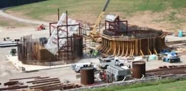

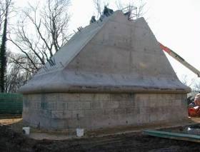
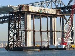
4 What is Mass Concrete?

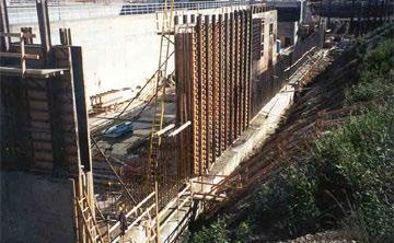
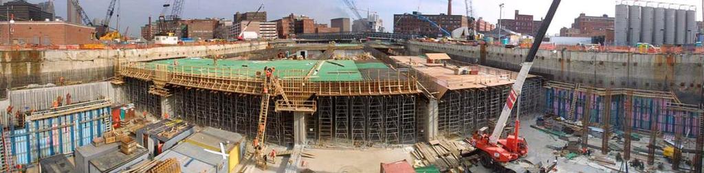
5 What is Mass Concrete?

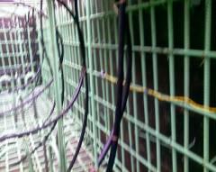
6 Drilled Shafts too! What is Mass Concrete?


7 Why the Focus? Larger elements Flowable concrete Rapid construction Long service life
8 When is it Mass Concrete? When rate of heat generation and thickness is such that heat is generated much faster than it escapes. ACI 301 says it is mass concrete when Thickness 4 ft >660 lb/yd 3 cementitious Minimum dimension and/or cementitious content for treatment as mass concrete varies greatly by authority
9 Chart from: Gajda, J., Feld, J., & Ferraro, C. C. (2018). Proposed Mass Concrete Definition Based on Concrete Constituents and Minimum Dimension. American Concrete Institute Special Publication, 325, 7-1. When is it Mass Concrete?
10 Maximum Temperature Typically limited No consensus in specifications Safe limit: 158/160 F Concrete mix design Cement (type and quantity) SCMs (type and percentage)

11 Delayed Ettringite Formation (DEF) Potential durability issue that can occur when: Concrete temperature exceeds 158/160 F Cementitious materials have particular chemistry External water available during service life Expansion and cracking
12 Temperature Difference Often limited to a maximum of 35 F (20 C) Generalized rule-of-thumb Discovered during construction of unreinforced dams in Europe 75+ years ago May not prevent thermal cracking Simple to use and understand Extends construction time


13 Thermal Cracking Durability concerns Reduced service life Structural concerns
14 Drilled Shafts as Mass Concrete Some DOTs and other entities recognize treatment of drilled shafts as mass concrete Minimum dimension varies (4-ft? 8-ft? 12-ft?) Required cementitious content varies Many DOTs and other entities explicitly EXCLUDE drilled shafts as mass concrete No temperature monitoring = unknown issues (DEF, thermal cracking) Cannot inspect surface for thermal cracking (drilled shaft buried or in casing) Control methods more difficult and limited in drilled shafts, but can be done
15 CONTROL STRATEGIES FOR MASS CONCRETE DRILLED SHAFTS
16 Temperature Difference Limit Stepped limit Steps up with age (e.g F) Shortens construction time Can lead to thermal cracking if not used with appropriate concrete properties Engineered (tailored) limit Often called performance-based temperature difference limit (PBTDL) Accounts for concrete s ability to withstand higher thermal stresses as strength of the concrete increases Based on specific measured concrete properties and structure ACI 207.2R-95
17 Allowable Temp. Diff., F Calculated (Example) Specified 35 F In-Place Compressive Strength, psi Temperature Difference Limit (cont.)
18 180 Allowable Temp. Diff., F Calculated (Example) Specified 35 F In-Place Compressive Strength, psi Temperature, F Calculated dt 35 F dt Time, Days Temperature Difference Limit and Time Savings

19 Maximum Temperature: Ballpark Temperature Rise Estimated Rise = 0.16*(portland cement + F*slag cement + 0.5*fly ash (class F) + 0.8*fly ash (class C) + 1.2*silica fume) F = 1.0 to 1.1 for 0 to 20% portland cement replacement 1.0 for 20 to 45% portland cement replacement 0.9 for 45 to 65% portland cement replacement 0.8 for 65 to 80% portland cement replacement
20 Maximum Temperature Estimation Max. Temp. = Initial Temp. + Temp. Rise - Loss Initial Temperature As low as economically practical (Payback of 1:1) Temperature rise depends on mix design Equivalent cement content Loss (Early heat loss) Negligible for placement >5 ft thick Cooling pipes
21 For example Drilled Shaft 400 lb/yd 3 cement and 300 lb/yd 3 class F fly ash 85 F initial concrete temperature 8 ft diameter No cooling pipes Temperature Rise = 0.16*( *300) = 88 F Maximum Temperature = = 173 F
22 BE CAREFUL!!! The ballpark temperature rise and preceding example DO NOT account for all factors which influence the temperature rise! Thermal modeling does account for all factors which influence temperature rise, some of which include: Existing adjoining concrete and its temperature Placement on/against soil or other subsurface material Insulation R-value on placement Average air temperature or soil temperature surrounding placement Minimum dimension of placement and overall geometry Type and specific source of cement and SCMs Cooling pipes


23 Control Strategies (Max. Temp.) Cool the Interior Precool the concrete Cooling pipes


24 Precooling Use cold batch water 2-3 F reduction Replace batch water with ice Up to 20 F reduction Liquid nitrogen precooling Unlimited precooling
25 Cooling Pipes Remove internal heat after concrete placed Reduces max. temperature Reduces temp. difference Reduces time of thermal control ¾ or 1 plastic cooling pipes Typically grouted afterwards Uses river/site water or chiller and tank system

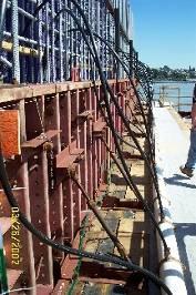


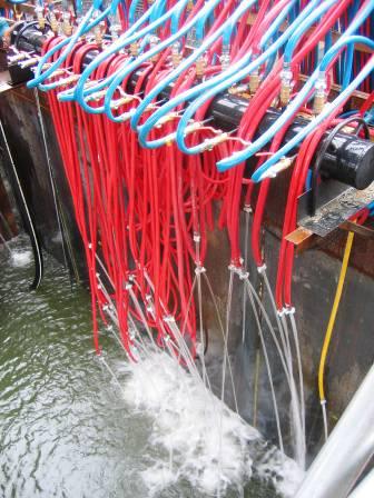
26 Cooling Pipes
27 No Cooling Pipes vs. Use of Cooling Pipes Temperature, F Temperature, F
28 Temperature Monitoring Monitor temperatures to demonstrate limits not exceeded Typical locations Geometric center of placement 2-3 inside the surface at center of large surface Hourly data Anecdote: Client just mentioned this on 3/29/2019 He had a contractor friend with 240 F drilled shaft Was not required to monitor per specification 12-ft diameter, so monitored anyway
29 Summary Concrete does not care where it is placed; it will still get hot! Cracking can be minimized/prevented through control of temperatures and temperature differences. PBTDL Cooling pipes Increased time of construction (but this can be minimized). Helps ensure service life is achieved.
30 Resources ACI , ACI ( PCA Publication EB547 ( ACI 207 Documents ( Gajda, J., Feld, J., & Ferraro, C. C. (2018). Proposed Mass Concrete Definition Based on Concrete Constituents and Minimum Dimension. Special Publication, 325, 7-1.
31 DISCUSSION/QUESTIONS?