STRUCTURAL STRENGTHENING SIKA CORPORATION, LYNDHURST, NJ AIA PROGRAM NUMBER: SIK302
|
|
|
- Milton Whitehead
- 5 years ago
- Views:
Transcription

1 STRUCTURAL STRENGTHENING PRESENTED BY: SCOTT DISTEFANO SIKA CORPORATION, LYNDHURST, NJ AIA PROGRAM NUMBER: SIK302
2 Key Learning Objectives Determine why structures need to be strengthened Highlight materials that can be used for structural strengthening along with their advantages and disadvantages Design considerations, along with available industry guidelines, for successful use of materials
3 This program is registered with the AIA/CES for continuing professional education. As such, it does not include content that may be deemed or construed to be an approval or endorsement by the AIA of any material of construction or any method or manner of handling, using, distributing or dealing in any material or product. Questions related to specific materials, methods, and services will be addressed at the conclusion of this presentation.
4 Sika Corporation is a Registered Provider with the American Institute of Architects Continuing Education Systems. Credit earned on completion of this program will be reported to CES Records for AIA members. Certificates of Completion for non-aia members is available upon request.
 This program qualifies for Health, Safety and Welfare (HSW) credit Please sign the form and add your AIA member number if you wish to obtain credit for this seminar Sika will forward this")
5 AIA/CES Program This AIA/CES program delivers 1 learning unit of credit (1.0 LU) This program qualifies for Health, Safety and Welfare (HSW) credit Please sign the form and add your AIA member number if you wish to obtain credit for this seminar Sika will forward this information to AIA so that you will receive credit for this presentation Non-AIA members may receive CEU s upon request

 Fibers")
 Reinforced concrete Concrete")
6 WHAT ARE COMPOSITES? Composites are a combination of two or more distinct materials Fiber reinforced polymers (FRP) Fibers (carbon or glass) Resins (epoxy matrix) Reinforced concrete Concrete (matrix) Steel (reinforcement)


7 WHY DO STRUCTURES NEED STRENGTHENING? Insufficient reinforcement Corrosion damage Change in use Structural damage Seismic upgrade 1950 s 2000 s

8 U.S. INFRASTRUCTURE American Society of Structural Engineers Report Card Overall grade of America s Infrastructure: D+ Over 600,000 bridges in U.S. 1 in 11 rated structurally deficient 4 in 10 bridges 50 years or older Total infrastructure needs: $4.59 TRILLION over 10 years 8
9 ADVANTAGES OF FRP REPAIRS Cost/scheduling benefits Get in, Get out, Stay out! - FHWA Mantra for accelerated construction Reduced maintenance costs Light weight materials puts less strain on infrastructure Non-corrosive materials are designed for long-term performance Less expensive repairs allow for more structures to be repaired with fixed budget 9
10 CONFINEMENT / SEISMIC Additional loads Earthquake Ductility
11 FLEXURAL STRENGTHENING 11
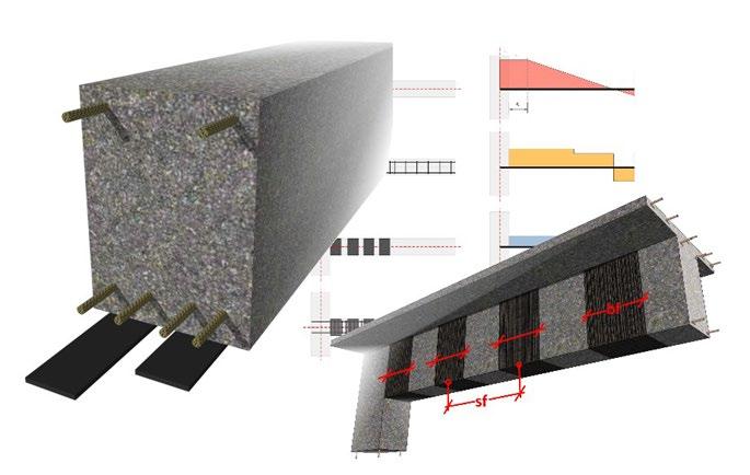
12 SHEAR STRENGTHENING 12

13 COMBINED STRENGTHENING - ANCHORAGE 13


14 EXTERNAL PLATE BONDING MATERIALS CFRP Strips Fabrics Brackets Steel Plates Jackets GFRP Fabrics


15 CFRP vs. GFRP Active loading Damp/wet conditions Stiffness driven Extreme alkaline conditions Passive/seismic loading Dry conditions Extreme acidic conditions Economical
16 Steel vs. Composites Low material cost High installed cost Corrosive Heavy Fabrication required High maintenance High material cost Low installed cost Non-corrosive Lightweight No fabrication required Low maintenance


17 TYPICAL APPLICATIONS Bridges Girder Strengthening Column Wrapping Pier Upgrades Deck Stiffening


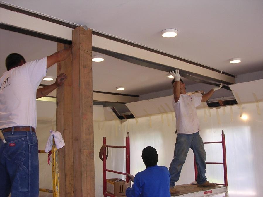
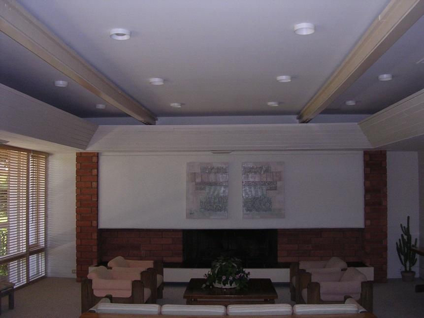
18 TYPICAL APPLICATIONS Buildings Modifications Change in use Wall strengthening Seismic upgrades


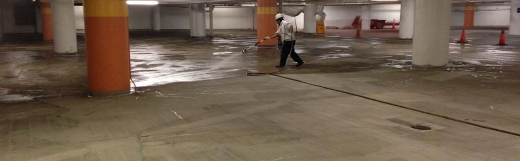
19 TYPICAL APPLICATIONS Parking Structures Shear Strengthening Corbel Upgrades Corrosion Damage

20 LIMITED ACCESS
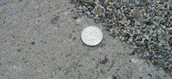
21 SURFACE PREP Concrete prepared by sandblasting Concrete smoothed out using grinders All defects repaired using epoxy mortar
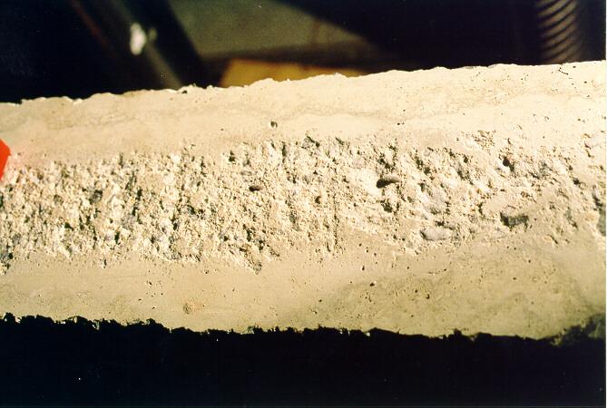
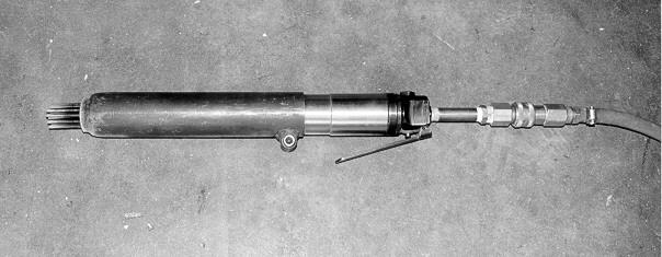
22 SURFACE PREPARATION


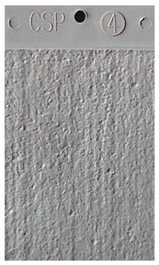
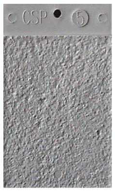


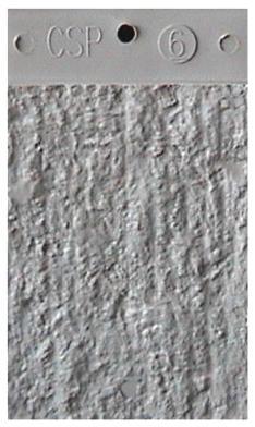
23 CONCRETE SURFACE PREPARATION Acid Etched Grinding Light Shotblast Light Scarification Medium Shotblast Medium Scarification Heavy Abrasive Blast Scabbled Heavy Scarification I.C.R.I Guideline # 03732


24 Testing Substrate Minimum tensile strength = 200 psi Substrate failure

25 SUBSTRATE PATCHING 25

26 PRE-CURED CFRP PLATES AND RODS 26

27 CLEANING CFRP STRIPS 27


28 CUTTING STRIPS ON-SITE 28

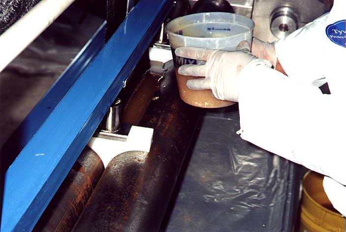
29 MIXING EPOXY RESIN Pre-mix components Low speed drill Uniformly blended


30 APPLYING EPOXY ONTO CFRP 30

31 APPLYING EPOXY TO SUBSTRATE 31


32 STRIP INSTALLATION Set strip by hand Work from one end to the other Moderate pressure 32


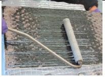
33 ROLLING CFRP ONTO CONCRETE Moderate pressure Ensures intimate contact 33

34 CENTRAL PARK WEST CONDO New octagon shaped staircase cut into reinforced concrete slab Carbon fiber plates inserted into grooves cut into concrete on top and bottom of slab 34

35 FRP FABRICS Available in carbon or glass Conforms to all shapes & sizes Unidirectional or Bidirectional Effective on concrete and masonry Wet or Dry Lay Up or Pre Saturated

36 SATURATING THE FABRIC Fabric Resin

37 SATURATING THE FABRIC MANUALLY 37

38 SURFACE PREPARATION Corners rounded to ½ minimum Blast clean surface Open pores Remove laitance Smooth and level

39 FABRIC APPLICATION


40 REMOVING AIR VOIDS

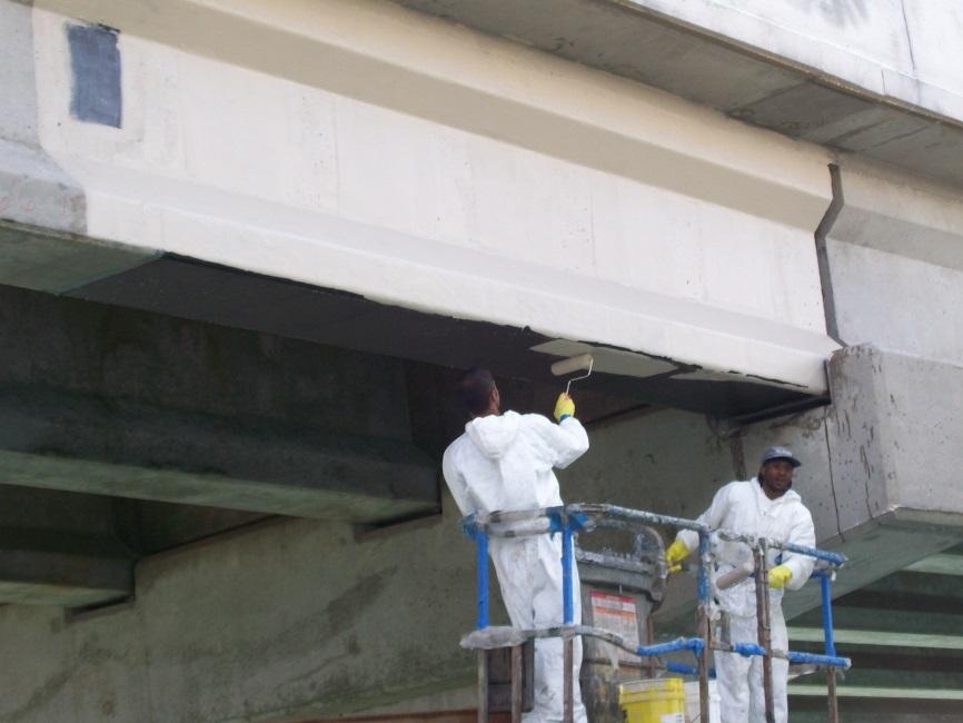
41 PROTECTIVE COATINGS Before After


42 MASONRY CAPABILITIES 27 osy unidirectional glass fabric with epoxy resin. 4-point bend deflection test.
43 FRP VS. CONVENTIONAL UPGRADE Simply supported beam; 35% upgrade in live load Bonded Steel Plate 3/16 inch bolted plate 245 lb. dead load Placed by lift truck Member Enlargement 2 #8 rebar, 4 in. grout 2,500 lb. dead load Formed and cured FRP Sheet 1 layer resin bonded 6 lb. dead load Placed by hand

44 DESIGNING WITH FRP Provides secondary reinforcement Must comply with local building and fire codes 44


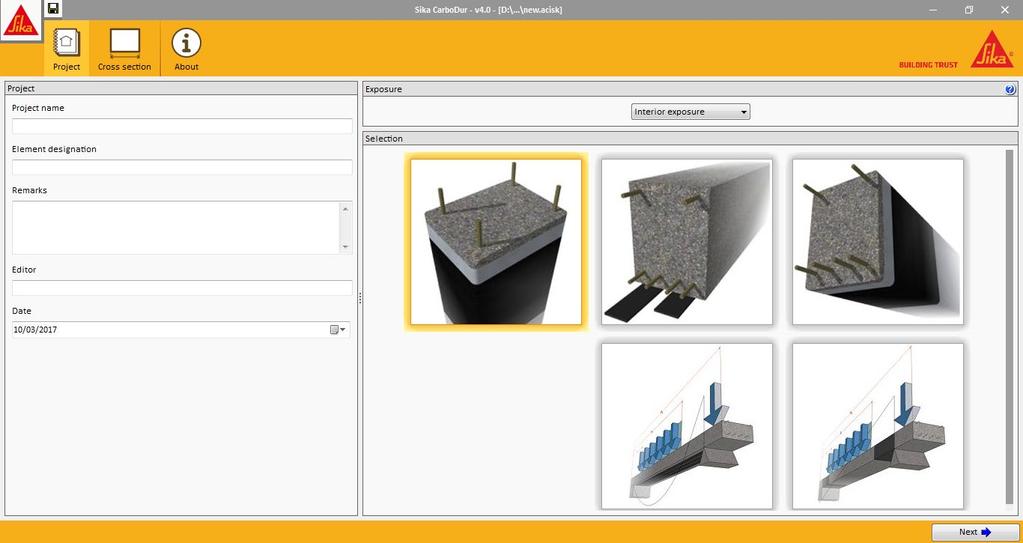
45 FRP DESIGN SOFTWARE 45


46 CODES AND STANDARDS ACI 440.2R-08 Guide for the Design and Construction of Externally Bonded FRP Systems for Strengthening Concrete Structures ACI Code Requirements for Evaluation, Repair, and Rehabilitation of Concrete Buildings Developed for adaptation into International Existing Building Code Use of FRP allowed as long as consistent with ACI 440 ICC Evaluation Service Technical evaluation of building products for compliance to building codes such as IBC Products independently tested per Acceptance Criteria 46
47 ADDITIONAL FRP APPLICATIONS

48 FRP RODS NEAR SURFACE MOUNTED REINFORCEMENT

49 SHEAR STRENGTHENING ANCHORAGE DETAILS FRP Rod Add Photo.. Structural Group

50 CARBON ROPE ANCHORS Anchoring and glass fibre fabrics on concrete or masonry Connecting carbon or glass fibre fabrics through concrete or masonry structures Flexible near surface mounted strengthening (NSM)

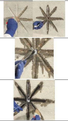
51 CARBON ROPE ANCHORS

52 CARBON ROPE ANCHORS

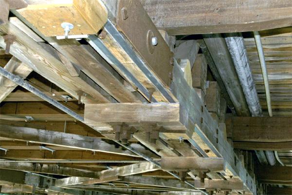
53 WOODEN MEMBERS


54 GLULAM BEAMS
55 POST-TENSIONING WITH CFRP Optimal use of Carbon Fiber Plates Reduces tensile strain in existing steel reinforcement Increases live load capacity of member Non-corrosive material adhesive Post-tensioned CFRP plate anchor anchor

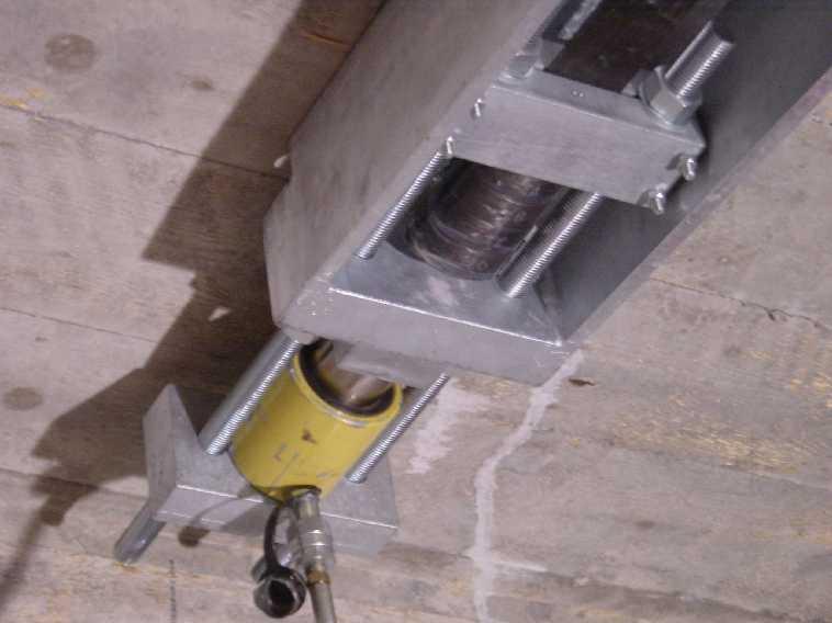
56 Live End Dead End


57 BLAST DESIGN Embassy work Combat terrorism Chemical & Industrial Plants Airports Baker Engineering


58 BLAST HARDENING Brittle response of unretrofitted column to blast load Ductile and nearly elastic response to same blast after wrapped with fiber reinforced polymer (FRP)
59 PRESATURATED SYSTEMS
60 BACKGROUND Structural Strengthening was typically done with retrofitted steel Cheap material but Labor intensive and added significant weight In the 1980 s FRP composites started to be used for strengthening concrete Light weight Easy to apply Material cost offset by ease of application Early-mid 1990 s, Sika rolls out CFRP & GFRP systems for SikaWrap 103C and SikaWrap 100G Great success Extremely messy Quality control in the field is difficult 2015, Presaturated Fabrics are introduced into the market 67
61 STRENGTHENING EVOLUTIONS STEEL Low material cost High installed cost Corrosive Heavy Fabrication required Difficult on site adjustments High maintenance COMPOSITES High material cost Low installed cost Non-corrosive Light weight No fabrication Easy field adjustments Low Maintenance Transition from steel to composite is near 100% 68
62 STRENGTHENING EVOLUTIONS COMPOSITES High material cost Low installed cost Needs resin Light weight Low maintenance No fabrication PRESAT. COMPOSITES Higher material cost Lower installed cost Resin included Light weight Low maintenance No fabrication Can PreSaturated composites be the new normal? 69


63 BACKGROUND PreSaturated FRP systems are not new Used in aerospace industry Previously required: Refrigerated/Frozen storage Short shelf life Autoclave post cure Custom, highly specialized equipment 70


64 THE NEXT GENERATION OF FRP! PreSaturated FRP is the next generation in strengthening technology! 71
65 CURRENT FIBER WRAP SYSTEM Order & Ship Resin Order & Ship Fabric Prepare concrete Bring Saturator on site Mix Epoxy Primer Prime Concrete Fabric is cut on site (if necessary) Set up saturator Fabric is then saturated (saturator or table/rollers) Piece by piece, saturated fabric transported and given to installers Applied to primed surface Left to cure Clean up saturator and site Dispose of Resin pails 72
66 CURRENT FIBER WRAP SYSTEM Order & Ship Resin Order & Ship Fabric Prepare concrete Bring Saturator on site Mix Epoxy Primer Prime Concrete Fabric is cut on site (if necessary) Set up saturator Fabric is then saturated (saturator or table/rollers) Piece by piece, saturated fabric transported and given to installers Applied to primed surface Left to cure Clean up saturator and site Dispose of Resin pails 73


67 CURRENT FIBER WRAP SYSTEM Prep Work 74


68 CURRENT FIBER WRAP SYSTEM Repair Imperfections 75


69 CURRENT FIBER WRAP SYSTEM Mix & Apply Epoxy Primer 76

70 CURRENT FIBER WRAP SYSTEM Cut fabric to size 77


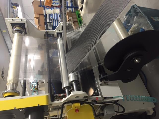
71 CURRENT FIBER WRAP SYSTEM Saturate Fabric with Resin Table or Saturator 78


72 CURRENT FIBER WRAP SYSTEM 79

73 CURRENT FIBER WRAP SYSTEM 80

74 CURRENT FIBER WRAP SYSTEM 81
75 PRESATURATED SYSTEM Some initial Steps are the same... Order Fabric Prepare concrete Mix Primer Prime Concrete Now it changes... Cut open pouch Cut fabric if necessary Applied to primed surface Left to cure 82

76 PRESATURATED SYSTEM Prep Concrete 83


77 PRESATURATED SYSTEM Mix Epoxy Primer 84

78 PRESATURATED SYSTEM Prime Concrete 85


79 PRESATURATED SYSTEM Open foil pouches when ready to apply 86

80 PRESATURATED SYSTEM Cut wet fabric if necessary 87

81 PRESATURATED SYSTEM Lay Wrap 88

82 PRESATURATED SYSTEM Finito 89


83 WHERE TO USE In difficult or standard applications such as: Load Increases Increased live loads Increased traffic volumes on bridges Installation of heavy machinery in industrial buildings Vibrating structures Changes of building utilization Seismic Strengthening Column wrapping Masonry walls Damage to Structural Parts Aging of construction materials Vehicle impact Fire Blast resistance 90 Change in Structural System Removal of walls or columns Removal of slab sections for openings Design or Construction Defects Insufficient reinforcements Insufficient structural depth

84 WHERE TO USE In difficult or standard applications such as: Load Increases Increased live loads Increased traffic volumes on bridges Installation of heavy machinery in industrial buildings Vibrating structures Changes of building utilization Seismic Strengthening Column wrapping Masonry walls Damage to Structural Parts Aging of construction materials Vehicle impact Fire Blast resistance 91 Change in Structural System Removal of walls or columns Removal of slab sections for openings Design or Construction Defects Insufficient reinforcements Insufficient structural depth New Application Areas? Telephone Poles Under water Tidal Zones Low/High Temp
85 ADVANTAGES Quality in the field Known Resin to Fabric Ratio Within 5% Material Certs for engineers Strengths Modulus R:F Ratio ISO 9001 Plant Full Traceability Drop in replacement for current products Reduction in Labor Reduce 5-6 man crew by 2-3 men Application efficiency Increase work rate by 20-30% 4 day project down to 3 No need to move saturated fabric around Ease of delivery Single source Non hazardous Can be easily transported or air freighted 92

86 ADVANTAGES MANUFACTURING How manufactured materials are traced: All raw materials include lot # and quantity Sales order generated = work instruction in system Includes BoM and lot # of each raw material Work instructions are converted into 6 digit lot number 93

87 ADVANTAGES PACKAGING 94

88 ADVANTAGES PACKAGING 95
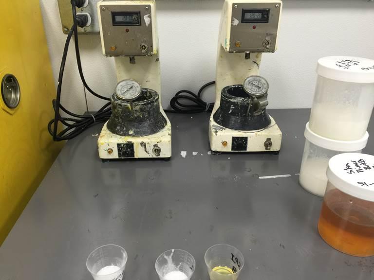
89 ADVANTAGES QUALITY CONTROL Quality tests performed during processing of fabrics: Resin to fabric ratio content Target 50% +/-5% FTIR test (i.e. this is like a fingerprint test to make sure resin matches previous batches) Target 99% match Gel time target 140⁰F (ASTM ) Quality test performed for primer (i.e. Sikadur 340) FTIR of A and B Target 99% match Gel-time target 93 mins Viscosity Glass transition temperature goal >144 ⁰ F 96

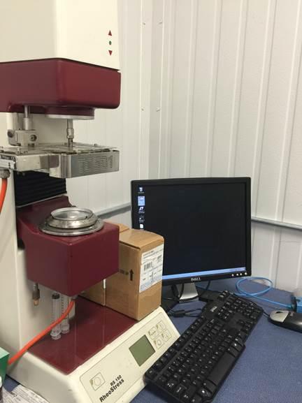
90 ADVANTAGES QUALITY CONTROL 97

91 ADVANTAGES QUALITY CONTROL 98

92 ADVANTAGES QUALITY CONTROL 99
 30K sq.ft.")

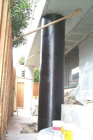
93 RFK BRIDGE SCOPE OF WORK Confinement wrapping of existing columns (& some beams) 30K sq.ft. Band aid for now while bridge work continues Coating of finished wrap for aesthetics and UV protection All work needs to be completed by the end of September. 112 April 8, 2019

94 RFK BRIDGE ORIGINAL DESIGN Designed by LIRO Group Been on the job with Sika for over 3 years & multiple phases Original design was 28 oz glass fabric Applied as a wet layup, 1 layer. Epoxy primer and saturant Contractor was awarded the job New applicator Very familiar with typical systems 113 April 8, 2019
95 RFK BRIDGE CONTRACTOR TRAINING CBM came into Sika to receive training on systems and applications Applied 28 oz glass fabric as a wet layup Introduced to PreSaturated Glass Fabric Immediately switch gears No longer want to saturate CBM sees major benefits Cleaner Faster Much less labor plan on only 2 man crew Glass PreSaturated Fabric was submitted to LIRO as a substitution. Submitted PDS & SDS Quickly accepted as a substitution 114 April 8, 2019

96 115 April 8, 2019

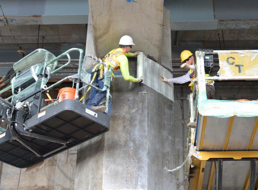
97 116 April 8, 2019


98 117 April 8, 2019

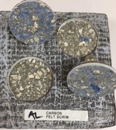
99 RFK BRIDGE HOME STRETCH Only 2 days after deadline and project is complete. Inspector on job constantly has now approved all work 30K sq.ft. have been wrapped and coated Bulk of the work was done with 2-3 guys on site at a time 118 April 8, 2019


100 119 April 8, 2019

101 120 April 8, 2019

102 121 April 8, 2019


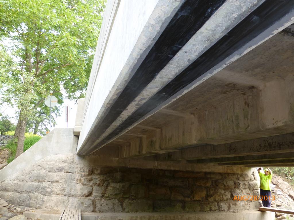
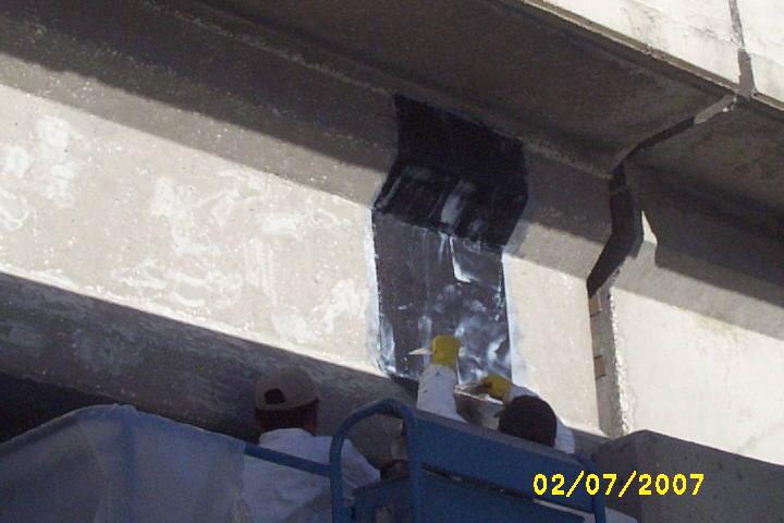
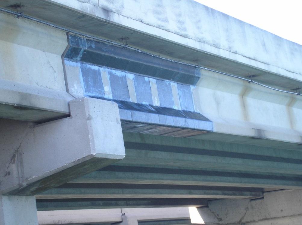
103 12 Sika / PennDOT 2015 Pilot Program Condition: Cracking under the open parapet joint in Non-Composite Pre-Stressed Box Beam Bridges. Project Team: Carbon Engineering Tilden Township Upper Bern Twp Sika Corporation

104

105 12

106 12
107 PILOT PROGRAM EVALUATION 1. PRIOR CONVENTIONS REPAIR METHODS: 2. PREVIOUSLY COMPLETED REPAIRS WERE MADE AT $1,500 - $2,500 / LINEAL FOOT 3. CUT CHIP AND REMOVE 4 PER EXPANSION JOINT (2 ON EACH SIDE OF JOINT). 4. INSTALL AND WELD SUPPLEMENTAL STEEL REINFORCEMENT. 5. RISK OF FURTHER DAMAGE TO BRIDGE. 6. INSTALL SCHEDULE COULD BE 5 7 DAYS 7. ROADWAY SHUTDOWN DURING INSTALLATION. 8. SIKAWRAP PRE-SATURATED CFRP REPAIR METHODS: 9. REPAIRS POSSIBLE WITHIN 2 DAY WINDOW. ROAD CLOSURE WAS NOT NECESSARY. 10. COMPLETED REPAIR COST OF APPROXIMATELY $450 / LINEAL FOOT MUNICIPAL LABOR. 11. COMPLETED REPAIR COST OF APPROXIMATELY $600 / LINEAL FOOT CONTRACTOR LABOR. 12. SIKAWRAP PRE-SATURATED CFRP REPAIRS 4X 5X MORE COST EFFECTIVE THAN PRIOR METHODS. 13. ALL REPAIRED BRIDGES REMOVED FROM 6 MONTH INSPECTION SCHEDULE.
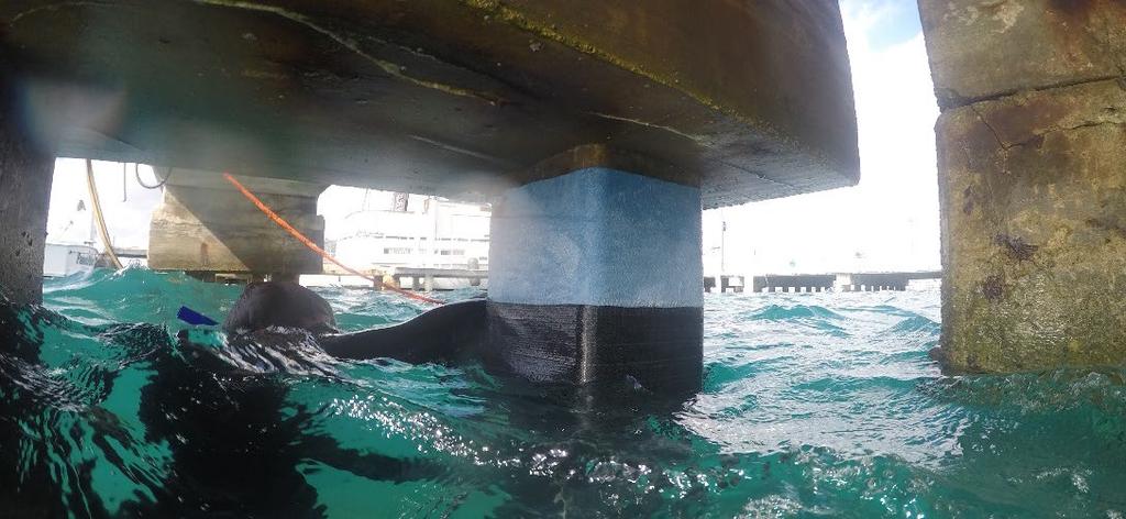
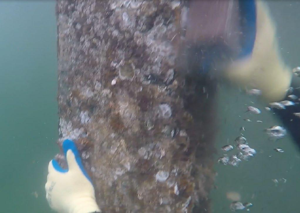
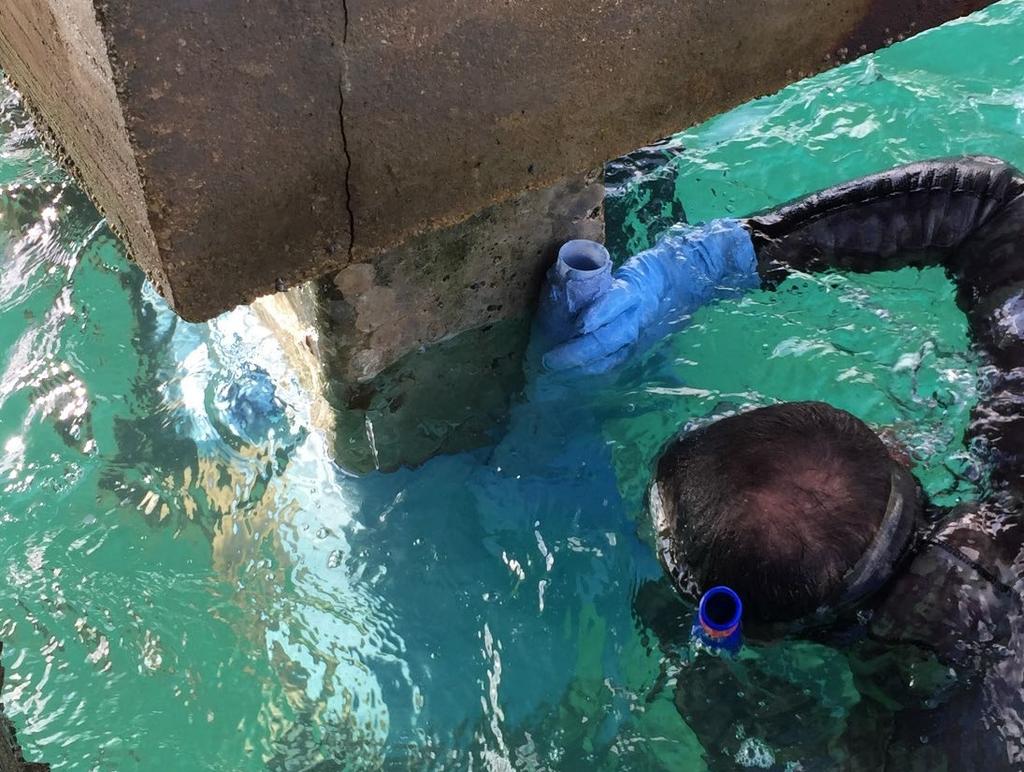
108 UNDERWATER FRP
109 MOTIVATION FOR AN UNDERWATER PRODUCT DEVELOPMENT Composite have gained a wide acceptance for structural strengthening of concrete structures Most of the strengthening applications are done in dry environment due to the sensitivity of these materials to cure in the presence of moisture. There is a demand and need for an FRP system which cure in the presence of water FRP jackets have been successfully used in many projects to protect structures, however they are size specific and require a complex repair process.
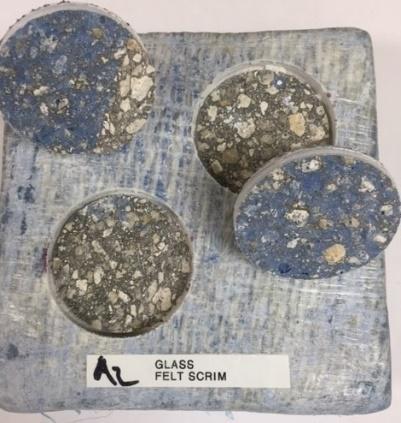
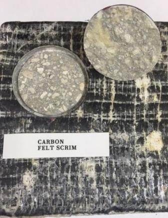
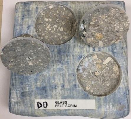
110 RESEARCH GOALS Develop an epoxy formulation that meet following parameters Cures underwater It is environmentally safe (mix product) Minimum bond strength of 200 psi with pre-preg, with concrete failure as a desirable failure mode Work time >90 mins with >80 % cure in 5 days. Must be able to apply easily underwater Tg of the system is 150 F (66 C)
 Glass")

111 DURABILITY TEST All Samples tested retained 90% bond strength from control sample Failure Modes of most samples were 100 % cohesive on concrete Environments Durability Test Results Carbon System Polypropylene felt (psi) Glass scrim (psi) Polypropylene felt (psi) Glass System Glass scrim (psi) Control Water resistance Salt water resistance Alkali resistance wet Dry heat resistance
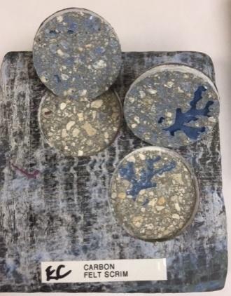
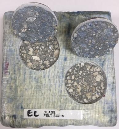
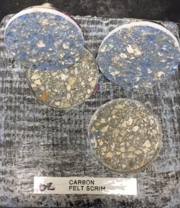
112 DURABILITY TEST CONTINUED Water Resistance Salt Water Resistance Alkali Resistance Heat Resistance

113 COMPRESSION TESTING Systems tested: 1 layer of 18 oz presaturated carbon 1 layer of 18 oz presatruated carbon with UWP lab cure 1 layer of 18 oz presaturated carbon with UWP underwater cure Strain gauge applied at the surface of each tested cylinder
114 COMPRESSION TEST RESULTS IN GRAPHICAL FORM Baseline set at 8,000 psi. There is a 6% C. Strength reduction between dry and wet applications.

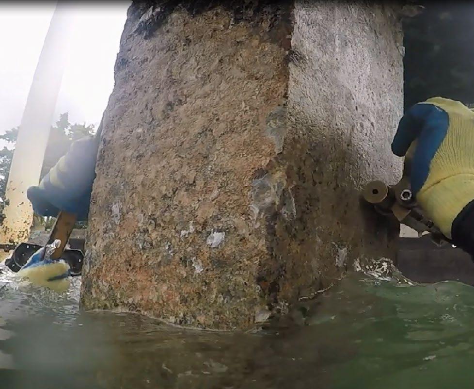
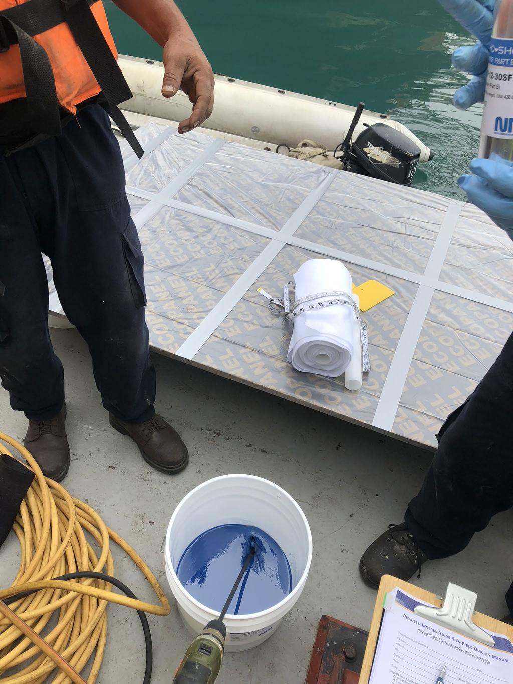
115 IN FIELD APPLICATION


116

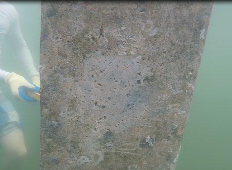
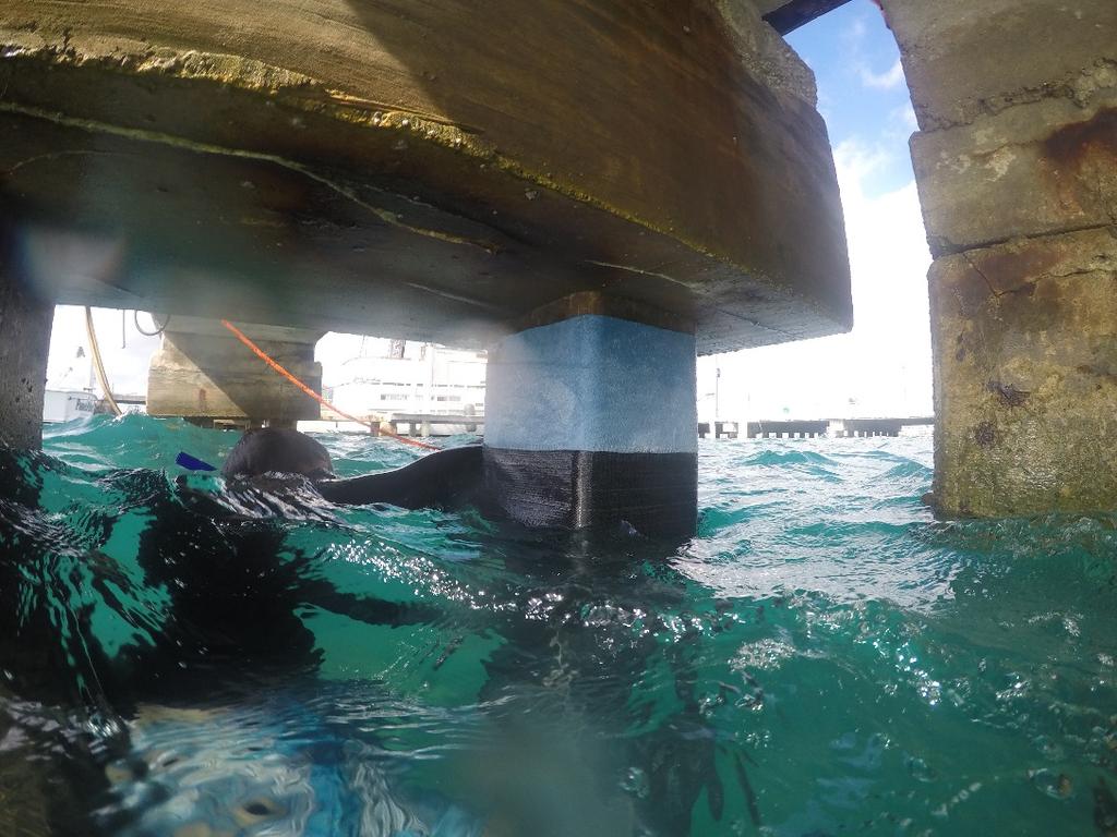
117 FIELD APPLICATION #2 136
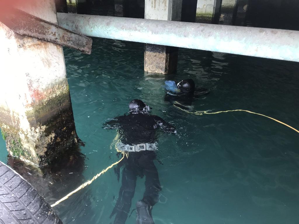
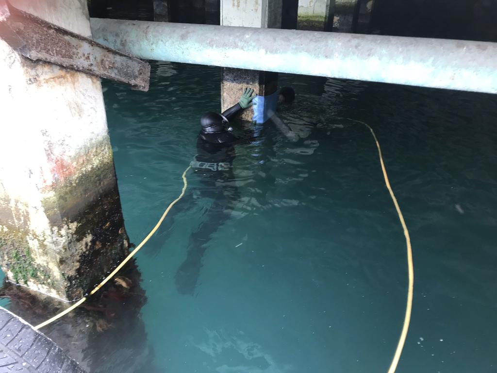
118 FIELD APPLICATION #2 137
119 QUESTIONS? THANKS FOR LISTENING!
120
121

122