TurfTrax from GT Trax
|
|
|
- Bruno Bell
- 5 years ago
- Views:
Transcription

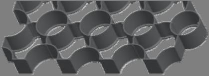
1 TurfTrax from GT Trax Patent Application Number Registered Community Design Application Number
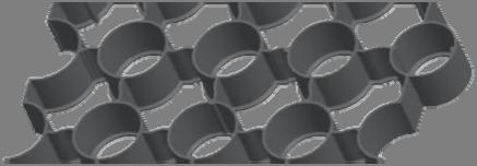

2 Dimensions Wall thickness, Wall height Weight per tile Weight per m²: 33 cm x 33 cm x 4 cm 3 mm, 40 mm 0.57 kg 5,13 kg

 Humidity absorption: 0,01 % Environmental")

 95% Recycled using")


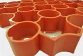
3 Material: 100% recycled polyolefin Compressive strength: Up to 10 t axle load in accordance with DIN 1072 Loadbearing capacity: Up to 320 tonne per square metre Natural stability: Temperature range -50 C up to 90 C Dimensional changes: Approx. 0,5 % (at a standard temperature +20 C up to 80 C) Humidity absorption: 0,01 % Environmental compatibility: Solubility: Installation: Harmless, groundwater neutral, weatherproof and UV resistant Resistant against acid and leaching, alcohol, oil and petrol (strewing salt, ammonia, acid rain etc.) 100 m² per person per hour TurfTrax (S) 100% recycled with no added colours TurfTrax Types TurfTrax (M) 98% recycled with colourants to produce a green or black product TurfTrax (H) 95% Recycled using segregated material to produce a consistent colour Benefits: Applications: Fully compliant with new planning requirements surrounding driveways to the front of properties. Environmentally Friendly Prevents erosion and wear on footpaths Interference connections creating stronger intergrid unions Strengthens grassed areas Minimal dimensional change due to temperature Resistant to water, corrosion and cracking Holds gravel and prevents rutting Strong geometric design ensures high compression strength Green parking Emergency vehicle access Temporary and permanent roadways Quick fit shed bases Road protection Embankments Green roofs Driveways Tree beds Golf walkways Caravan Parking Ménage s Hard standing Delineators TurfTrax has been designed to accept a standard delineator which should be fitted before filling and can be bought is a variety of colours. These can be used to create white lines, shapes or words as required. Interference Connection
 compliant solution.")


4 TurfTrax permeable paver grid is the new recycled plastic sustainable drainage system (SUDS) compliant solution. Using a patent pending design to avoid breakage problems on installation, R-Pave is a high performance, durable and virtually maintenance free solution for use with grass or gravel. TurfTrax is manufactured from 100% recycled polyolefins and provides a lightweight ground reinforcement system for grass and gravel stabilisation. This type of surface helps to reduce the risk of potholes, rutting or grass damage. TurfTrax has been designed to support healthy grass growth providing a minimum of 3.2cm of available height to allow the grass sufficient height in which to grow. The system design provides a lightweight strong structure making it easy and quick to install and suitable for a wide range of applications including paths, driveways, car parking areas and access routes. Correctly installed TurfTrax has been demonstrated to withstand up to 350 tonnes per square metre. TurfTrax offers unimpeded flow to surface water reducing the rate of run off and potentially saving the costs of drainage installation. B-Gard Edge Restraint TurfTrax utilises a patent pending design that uses interference connectors to ensure a strong lateral joint between each grid removing the risk of connectors breaking during installation. It is necessary to include a substantial edge system when installing TurfTrax permeable paving with grass or gravel finishes. The edge restraint needs to be sufficiently robust to withstand thermal expansion, vehicular movement, and prevent loss of laying course material. Typical examples of suitable edge restraints include kerbs, channels, existing structures, and rigid abutments such as securely fitter paving blocks. GT Trax offer the B-Gard edging system to provide suitable edging restraint in areas where alternative support is missing. Made from recycled plastics the strip can be used for straight edges, curves and bends.
. 1.")


5 Installation The product is asymmetric and must be lifted by placing the hands on the diagonally opposed corners of the central paver (as shown). 1. Place grids onto the prepared well consolidated bedding layer. Edging strips or boards should be used where required, according to ground conditions. 2. Connect the grids using the patent pending interference loops, progressing over the area in manageable sections. Additional pins can be used at edges to further strengthen the final installed project. Use protective gloves to avoid abrasions. 3. Grids can be cut using a hand or power saw to fit around obstructions and curves. Cut pieces which are less than 50% of original size should be avoided if at all possible. 4. Fill pavers with appropriate material. If using grass please use the specified rootzone material. Finished levels should be 5-7mm below the top of the cells. Do not overfill the grids. A light vibrating plate can be used to consolidate the grids and to settle the rootzone infill if required. 5. Rootzone must be free-draining structurally sound sand/compost or sand/soil blend. Normally this should be a propriety blend of 60:40 or 70;30 ratio. 6. Sow seeds normally, fertilising and watering as required. A light top dressing may be applied to just cover the seed and to provide adequate germination conditions. Do not overfill the grids. The surface may be trafficked immediately after filling but it is preferable to allow the grass to become established before full use. Sown Grass TurfTrax filled to within 5-7mm of the surface with 60:40 rootzone (see notes) then seeded or turfed and fertilised Images showing the correct methodology to pick up and handle a square metre of TurfTrax Sub-base layer thickness as determined by tables and information in notes TurfTrax Laying Diagram 1) Prepare the ground according to the use 2) Start to lay the R-Pave in the corner and lay it step by step Geotextile Layer to suppress weeds Bedding layer: 50mm thick consolidated 60:40 rootzone (see notes)

 If using concrete edging pieces, install them next. If using GT Trax B-Gard install these between steps 4 and 5.")
6 Installation 1) The area to be reinforced should be marked out and excavated to the appropriate depth (see table). Depending on soil conditions and intended use of the area to be stabilised, dig out the existing base e.g. typically for light vehicle traffic / parking areas, mm will suffice. With heavy wheel loads or a clay soil, 400mm may be necessary. Geo-textile membrane should first be laid on the earth before the base layer to create ground stability NB. Seek engineering advice where appropriate. 2) If using concrete edging pieces, install them next. If using GT Trax B-Gard install these between steps 4 and 5. 3) Compact the sub-base using a plate compactor. Fill the excavated area with free draining gravel or crushed stone to 100mm (grass) or 80mm (gravel) below the finished level. Tamp down with a roller or plate compactor. 4) Level the area with a layer of fine aggregate or for grass sieve sand/compost/loam mix. Level using a rail or wooden batten and compact as shown in the diagram across. This is used to level out any imperfections or hollows within the surface of the sub-base, and if the area is to be grassed over, it provides an ideal environment for grass root survival and growth. 5) If using R3 Products B-Gard to edge the area, install it at this stage. Once the whole area is completely level, you can proceed to interlock and lay the paving grids. They come pre-assembled in one square metre sections. Any that need cutting should be measured and cut prior to installation and where possible cut in such a way to leave complete cells along the outer edge. With the area completely laid and positioned correctly, the whole area can be lightly compacted ensuring that they remain flat and level. 6) The area can then be back filled with the medium to be used. If using gravel, we recommend 10mm or less as this allows better filling of the chambers. If the area is to be grassed, we recommend using a 70/30 rootzone mixture which is essentially a mixture of quality topsoil and sharp sand. This prevents the hard compaction of topsoil alone which can limit grass growth. Initially the cells should be filled to approximately 10mm below the top surface, this will protect young seedlings during early establishment. The whole area can then be seeded and watered in.
7 Calculations for Quantities Hardcore/Broken Stone required for the base layer For cars = 300kg of hardcore/broken stone per m² (providing 150mm depth) For trucks = 400kg of hardcore/broken stone per m² (providing 200mm depth) Sand or Fine Chippings required for the leveling layer For all grid types = 25kg of sharp sand (grass or gravel finish) or fine chippings (gravel finish only) per m² Topsoil required for a grass surface (per m2) For 40mm grid = 65kg of topsoil Aggregate required for a graveled area (per m2) For 40mm grid = 72kg of gravel TurfTrax Specification Bedding Layer 30mm thick of 5 20mm angular aggregate (BS EN 13242) Grid Fill To top of grids using 5 20mm crushed aggregate (BS EN 13242) Sub-base Layer DoT Type 3 or modified porous sub-base layer. DoT Type 1 with drains Typical Sub-Base Thickness Application Load CBR (%) Strength of Subgrade Soil (See Chart) DoT Sub-Base Thickness (mm) Fire Engine and occasional HGV Access Light Vehicle access and overspill car parking >=6 =4<6 =2<4 =1<2 >=6 =4<6 =2<4 =1< References: BS7533-3: A1:2009 BS7533-7:2010 BS :2009 BS EN13242: A1:2007 The Highways Agency: Specification for Highway Works The Environment Agency: Guidance on the permeable surfacing of front gardens Building Regulations 2010 Approved Document M1 Access and Use
8 The table showing sub-base thicknesses (Page 6) is intended as a general guide in accordance with BS7533. For further details on permeable paving design refer to BS7533 Part 13; for installation refer to BS7533 Part 3. The design for pavements should satisfy two parts - to support the traffic load and to manage the surface water effectively. Subgrade Assessment The strength of a subgrade is measured by California Bearing Ratio (CBR). The design CBR should be obtained either by testing or by measurement of the plasticity index of the subgrade material. In the case of CBR testing, the method described in BS1377 4:1990+A2:2002, Clause 7 should be used. The surface of the subgrade material should be prepared according to the Highways Agency s Specification for Highway Works, Clause 616. Detailed preparation of the subgrade should be in accordance with the recommendations in BS An acceptable subgrade level should be free of any soft spots, reasonably parallel to the plane of construction. A capping layer may be required if the ground is structurally weak, likely to be subjected to exceptional loads or is significantly below the specified ideal formation level. The table below gives typical values for the subgrade strengths (the CBR) normally encountered in the soils of Britain and Ireland Consistency Tactile (Feel) Indicator Visual (Observation) Strength Mechanical (Test) CBR CU SPT % kn/sqm Very Soft Hand sample squeezes through fingers Man standing will sink >75mm <2 <1 <25 Soft Easily moulded by finger pressure Man walking sinks mm 2-4 Around 1 Around 25 Medium Moulded by moderate finger pressure Man walking sinks 25mm Firm Moulded by strong finger pressure Utility truck ruts 10-25mm Stiff Cannot be moulded but can be indented by thumb Loaded construction vehicle ruts by 25mm Notes If the geotextile layer is omitted, then the total sub-base layer thickness should be increased by 50% A Department of Transport Type 1 sub-base may be used provided that an adequate drainage system is installed. Alternatively a porous subbase layer may be specified however this should be covered with either a geotextile filter membrane and/or suitable clean gravel blinding layer to avoid fine particles entering the sub-base layer. Specific advice regarding ground conditions should be sought from the manufacturer. Drainage details; 100mm diameter perforated pipe drain laid at a minimum gradient 1:100 bedded on gravel trench backfilled with suitable drainage aggregate, covered or wrapped with a suitable geotextile fabric and leading to a suitable outfall or soakaway. For specific advice contact the manufacturer. Rootzone bedding and grid fill must be free draining, structurally sound proprietary blend of sand/soil or sand/compost, this is normally identified as a 60:40 or 70:30 ratio blend and insitu blending is not recommended. Max advised gradient for traffic applications is 12%. Pegging may be required. R-Pave complies with BS8300:2001 The preparation of the subgrade, the construction of the sub-base and the construction and type of roadbase (if present) should generally be in accordance with relevant current practice as described in the Highways Agency s Specification for Highway Works. It is essential that the sub-base compaction is thorough, using a vibrating plate compactor or vibrating roller. The thickness of the laying course after final compaction of the surface course should be 40-50mm, within an accepted surface level tolerance. All areas of prepared laying course material should be protected and not left exposed overnight. The laying course may be placed and screeded using a mechanical device. It is necessary to include a substantial edge restraint when constructing R-Pave permeable paving with grass / gravel finishes. Edge restraints need to be sufficiently robust to withstand override by any anticipated traffic, to withstand thermal expansion and to prevent loss of laying course material. Typical examples of edge restraints are kerbs, channels, established structures, and rigid abutments such as securely fixed paving units.


9 Reduced Dig Systems Gravel 1. Cut the grass closely to the surface or where necessary remove the turf and topsoil to a depth of <75mm and dispose of all debris. Level the formation layer and lightly consolidate. 2. Install edge retaining boards or kerbs if required 3. Place a layer of geogrid stabilisation mesh or geotextile fabric on the formation layer and ensure that it is flat to the surface by pinning as required. An optional geotextile fabric layer can be placed on the formation layer prior to the geogrid installation to prevent migration & contamination. 4. Place a 35mm thick layer of 10mm diameter gravel / aggregate evenly over the geogrid. The geogrid must not be allowed to become exposed above the gravel / aggregate layer. 5. Place the R-Pave grass pavers onto the screeded gravel / aggregate layer. Connect the pavers using the ground spikes and loops, progressing over the area in rows. Use protective gloves to avoid abrasions. 6. Pavers can be cut using a hand or power saw fit around obstructions and curves. Cut pieces which are less than half the original size should be avoided where possible. Pavers can be firmed in place using a light vibrating whacker plate if required. 7. Fill the pavers with the specified gravel or aggregate. Preferably a clean, well graded angular material within the range of 5-14mm diameter. Fully rounded 'pea gravel' is not recommended. 8. Consolidate the surface using a light vibratory whacker plate if required. 9. Refill any localized low areas with gravel and repeat consolidation until satisfied with the final compacted finish. 10. The surface can be trafficked immediately. Grass 1. Follow steps 1-6 as for gravel. Note: It is not necessary to install the optional geotextile fabric layer as stated in Step 3(gravel). 2. Fill the pavers with the specified propriety rootzone. Finished levels should be 5-7mm below the top of the cells after settlement. Do not overfill the paver cells. A light vibrating plate can be used to consolidate the pavers and to settle the rootzone infill if required. 3. Rootzone must be a free-draining structurally sound sand:compost or sand:soil blend. This is a nominal propriety blend of 60:40 or 70:30 ratio. Self blending is not recommended. 4. Carry out a normal seeding, fertilising and watering programme. A very light top dressing may be applied to just cover the seed and to provide adequate germination conditions. Do not overfill the paver cells. Alternately thin-cut turf can be rolled into the surface if required. 5. The surface may be trafficked immediately, but it is preferable to allow the grass to fully establish prior to use. Yesterday s waste, Tomorrow s product