CHARTER TOWNSHIP OF HIGHLAND
|
|
|
- Mabel Bates
- 5 years ago
- Views:
Transcription


1 CHARTER TOWNSHIP OF HIGHLAND ENGINEERING DESIGN STANDARDS September 22, 2010 HUBBELL, ROTH & CLARK, INC. 105 W. Grand River Avenue Howell, MI HRC Job No
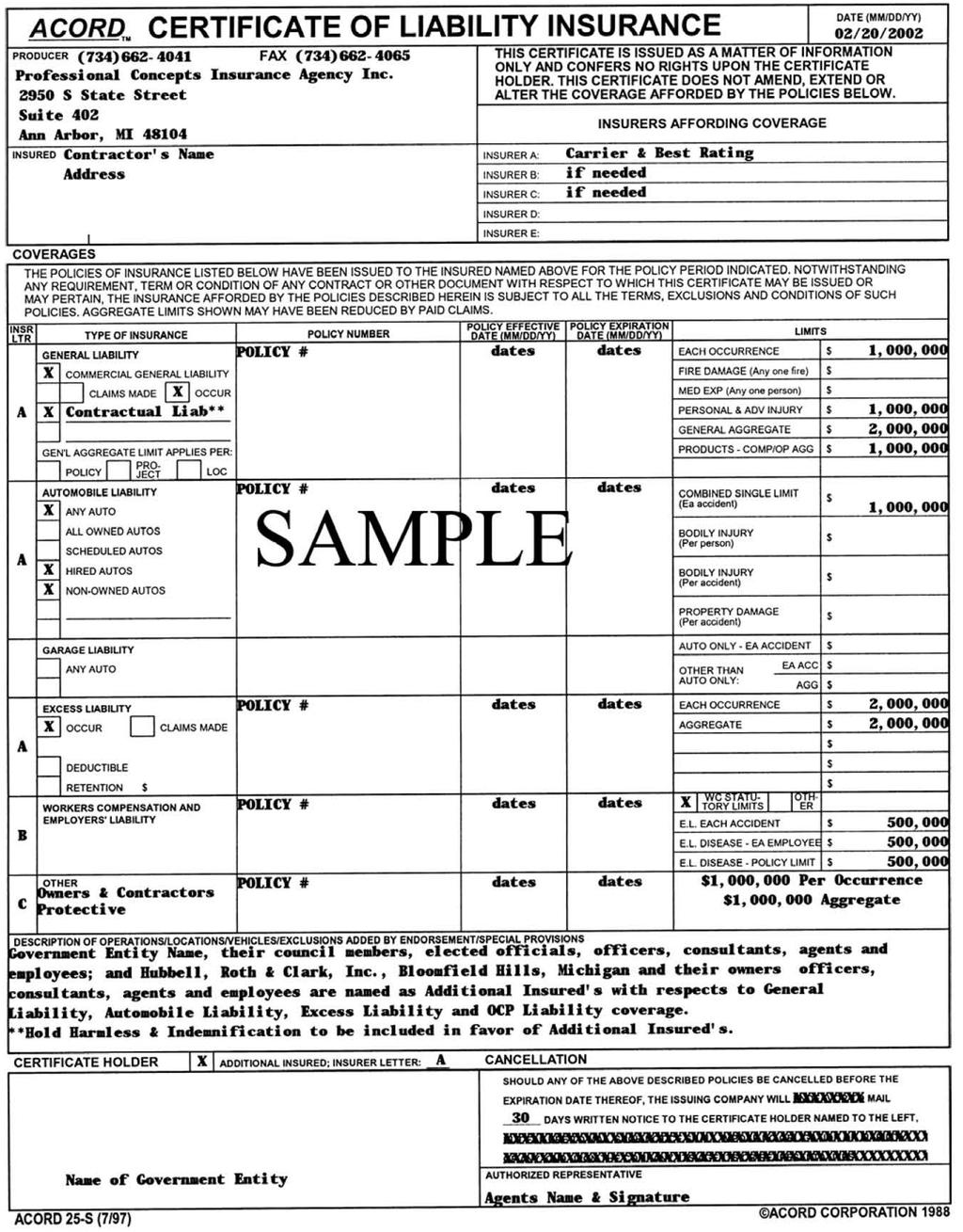
2 Engineering Design Standards These Engineering Design Standards are intended to provide a reasonable basis for design of public and private improvements in. They are not intended as a substitute for sound engineering judgment. The Standards may not apply to all conditions, and alternate solutions shall be permitted as approved by the Township s Engineer. Index Page No. SECTION 1 GENERAL... 2 PLAN REVIEW AND CONSTRUCTION PROCESS... 3 SECTION 2 WATER MAIN... 5 SECTION 3 SANITARY SEWER... 9 SECTION 4 STORM SEWER SECTION 5 STORM WATER DETENTION / RETENTION FACILITIES SECTION 6 GRADING SECTION 7 PAVING & PRIVATE ROADS SECTION 8 RECORD DRAWINGS APPENDIX A SAMPLE INSURANCE REQUIREMENTS Engineering Design Standards Page 1 of 26
3 Engineering Design Standards Page 2 of 26
4 Engineering Design Standards 1. GENERAL 1.1 Complete improvement plans bearing the seal of a licensed Professional Engineer, Surveyor or Architect licensed to practice in the State of Michigan shall be submitted prior to review and approval of any portion thereof. 1.2 A certified boundary survey of the site, prepared and sealed by a licensed Professional Surveyor licensed to practice in the State of Michigan, or a copy of the completed plat shall be submitted with the engineering drawings. 1.3 Plans submitted shall be on 24" x 36" white prints having blue or black lines, and shall be neatly and accurately prepared. Judgment should be exercised in the design, layout, and the presentation of proposed improvements. 1.4 For projects or subdivisions having more than one sheet of plans, a general plan having a scale of 1" = 100' shall be provided showing the overall project and indicating the size and general location of all improvements shown in the detailed plans. 1.5 Street names, street and easement widths, lot lines, lot dimensions, lot numbers and ownership shall be shown on all plans. 1.6 Elevations shall be on U.S.G.S. Datum. Two (2) permanent bench marks for the work shall be indicated on the plans. 1.7 Any areas that are considered to be "wetlands" as defined by the Michigan Department of Environmental Quality (MDEQ) shall be indicated on the plans. No improvements will be allowed in wetlands unless the MDEQ issues a permit, or a letter of "No Authority", for such improvements. 1.8 Finished grade shall be indicated for all structures. 1.9 The developer or their engineer shall be responsible to forward plans for approval to any private utility company (gas, electric, phone, cable, etc.) and any Federal, State or County (Drain Commission, Road Commission, etc.) agency whose facilities or rights-of-way may be affected by the proposed construction. Public utilities will require the review and approval of the Township prior to submittal to the permitting agency It shall be the developer s engineer and contractor's responsibility to verify the existence and location of all underground utilities and to utilize the MISS DIG system prior to construction All engineering construction plans shall contain the latest version of the applicable Standard Detail Sheets or the Oakland County Drain Commissioner (if applicable) and the developers/owners name(s), address, phone number and fax number. Engineering Design Standards Page 3 of 26
5 1.12 An Engineer s Opinion of Construction Cost must be supplied with the Construction Plan submittal. This estimate will be used by the Township to establish review and inspection fees for the improvements in accordance with the Township Ordinance All utility trenches under the 45 degree zone of influence line of existing or proposed pavements, bike paths, sidewalks or drive approaches shall be backfilled with sand compacted to at least 95% of maximum unit weight Utility crossings of paved roadways will be required to be bored. Open cutting of paved roadways will not be permitted An itemized quantity list will be required for all proposed utility improvements (water main, sanitary sewer, storm sewer, paving) The developer shall submit to the Township five (5) sets of complete construction plans for review. After the plans receive approval, they will be distributed as follows; one (1) set to the Township, one (1) set to the developer/owner and three (3) sets to the Township Engineer Plan Review and Construction Process Site Plan Reviews Engineering Design Standards Page 4 of 26 Consultant review of the preliminary site plan including water supply, wastewater disposal, storm water management, wetlands, site grading, pavement improvements and right-of-way improvements. Review comments will be issued to the Township Planning Commission for discussion at Planning Commission meetings. Once the Site Plan has been accepted by the Planning Commission, the Applicant will be required to submit Engineering Drawings and an itemized cost estimate of the proposed improvements so that an escrow account may be established for plan reviews and construction observation. Incorporation of Low Impact Development practices encourages the use of Low Impact Development practices including structural, vegetative, and managerial practices commonly known as stormwater best management practices (BMPs) designed to treat, prevent or reduce degradation of water quality due to storm water runoff. Consultant will consider any stormwater management plan designed in compliance with the Low Impact Development Manual for Michigan (LID manual) as published by the Southeast Michigan Council of Governments (SEMCOG) and may approve those plans that meet the standards of the Zoning Ordinance and stormwater quality and quantity standards defined herein. Engineering Plan Reviews Consultant review of the Engineering Plans for conformance to Township Engineering Design Standards. Once the plans are in an acceptable form, the plans will be issued as approved construction plans. The Applicant will be
6 responsible to apply for all required County and State permits including soil erosion, water supply, wastewater disposal, right-of-way, wetlands, etc. Public water main and sanitary sewer improvements will require the submittal of plans and permit applications for review and approval to be forwarded to the governing agency by the Township Engineering Consultant. Pre-Construction Meeting Once the approved engineering plans have been issued, a pre-construction meeting with the Applicant or their representative is required prior to the start of any site work. This meeting will verify that all relevant permits have been applied for, that the proper insurance is provided, and to schedule construction observation. A sample of the required insurance is included in Appendix A. Site Construction and Observation Once construction begins, the following construction observation is required: Roadways and parking lots including subgrade, aggregate base, curb and gutter, pavement installation, sidewalks and bike paths. Storm sewer installation and underground detention/retention systems. Water main installation and testing. Sanitary sewer installation and testing. Retaining wall installation. Additional construction observations may be required by the Township. The developer will be required to provide density testing for all public utility construction and work within the public road right-of-way. Bond Inspections and Final Inspections Once the proposed improvements have been completed, the Applicant may request that the Township perform a site inspection to establish bond amounts to complete the remaining site improvements for final acceptance by the Township. Record Drawing Plan Review Record drawings describing the location and elevations of the proposed site improvements are required to be submitted for review and approval. See Section 8 of the Township Engineering Design Standards for Record Drawing Requirements. Engineering Design Standards Page 5 of 26
7 2. WATER MAIN 2.1 General If the proposed improvements include the construction of public water main, the developer shall submit nine (9) sets of water main only plans (including the water main standard detail sheets) with a completed MDEQ permit application for water supply systems. This information will be forwarded by the Township s Engineer to the Oakland County Drain Commissioner (OCDC) and the MDEQ for permitting All water system improvements shall be designed in accordance with the current edition of "Recommended Standards for Water Works" (a/k/a Ten State Standards) Water mains in new developments shall be installed from boundary to boundary in abutting roads and interior streets, and at other locations and sized as may be deemed necessary by the Township for future extensions An itemized quantity list for all proposed water main construction must be included on the plans All public water mains must be located within a 20 foot wide easement or public road right-of-way. Easements should extend 10 feet beyond any hydrant. Sketches and descriptions of both the parcel and easement will be required. The documents shall contain a provision to prohibit the construction of any above ground structures within the limits of the easement. 2.2 Design Requirements The distribution system in all developments requiring more than 600 feet of water main shall have a minimum of two connections to a source of supply and shall be a looped system. Water mains are to be looped whenever possible. The ability to serve at least 2,000 gpm in singlefamily detached residential; 3,000 gpm in apartment, cluster residential and similar complexes, institutional, and school areas; and at least 4,000 gpm in office, industrial and shopping centers is essential Eight (8) inch minimum diameter mains will be installed in single family residential areas Twelve (12) inch mains are considered to be the minimum size in commercial, office, industrial, and multiple family residential areas except in a looped system of 1,500 feet or less where eight (8) inch mains may be permitted Water mains are to be looped whenever possible. Interconnection to existing public water supply systems is encouraged. Engineering Design Standards Page 6 of 26
8 Engineering Design Standards Page 7 of Hydrant leads longer than 20 feet must be eight (8) inches No service leads are allowed to extend from a six (6) inch hydrant lead Profile view is required for twelve (12) inch and larger water mains, and for other smaller sizes when determined necessary Water mains shall be kept on one side of the street for the entire length of the street. Water mains shall not be located under pavement or under cul-de-sacs Gate valves shall be spaced at a maximum of 800 feet intervals on distribution lines. They shall be spaced such that not more than four valves need to be turned off to isolate any section of the water main Sufficient valves shall be placed such that not more than 20 single family homes, 30 multiple family units or two (2) hydrants shall be out of service within a section of isolated water main Dead-end mains must end with a hydrant and a gate valve and well. All stubs for future looping must include a gate valve and well Gate valves should not be located under roadway pavement, bike paths, sidewalks or driveway approaches when possible Four (4) inch and larger valves are required to be installed in a gate well, except for six (6) inch hydrant shut off valves In single family residential areas, hydrants shall be spaced along the water main a maximum of 500 feet. In no case shall a house be more than 350 feet from a hydrant. Commercial, industrial and multiple family spacing shall be a maximum of 400 feet Along major roadways and in areas other than single family residential, hydrant spacing shall be a maximum of 500 feet In commercial and industrial areas, the exterior of buildings shall be no further than 300 feet from a hydrant, nor closer than 35 feet, measured along shortest feasible exterior route for laying hose. There shall be a fire hydrant located within 150 feet of any building fire department connection Where possible, hydrants shall be located at the lot corners, but no closer than eight (8) feet from any driveway or driveway approach Hydrants located in parking areas shall be protected with a six (6) inches (minimum) concrete curb or standard guard posts When connecting to an existing water main, a tapping sleeve, gate valve and well will be required unless connection to the existing main can be
9 made without interrupting service on the main The plans shall indicate the finish grades of all hydrants and gate well rims Water mains shall be located so as to provide a minimum of ten (10) feet horizontal clearance between the nearest edge of the water main and the nearest edge of any sanitary or storm sewer A minimum vertical clearance of 18 inches shall be maintained between the top or bottom of any water main and the top or bottom of any sewer or utility. Vertical clearance of less than 18 inches will require concrete encasement of the sewer or utility Restrained joints shall be used at all bends, tees, hydrant shoes, plugs and caps where necessary to prevent lateral movement of the water main. Thrust blocks will not be allowed unless required by the permitting agencies. 2.3 Materials All water main 18 inch diameter and smaller shall be Ductile Iron pipe, Class 54. Two (2) brass wedges shall be used per joint standard valve is East Jordan Iron Works C500 or C515, series A, Left Hand Open. All valves shall be resilient seated and conform to AWWA C509 Standards Hydrants shall be East Jordan Iron Works 5-BR traffic model with a five (5) inch Storz Pumper and two (2) 2.5 inch National Standard Thread Hose nozzles Restrained joints shall be Megalug or FieldLok gaskets Push-on type joints shall be Super Bell Tite or Tyton or approved equal. 2.4 Installation All water main shall be installed with a minimum cover of five-and-a-half (5.5) feet below finish grade or top of curb (or road centerline if uncurbed) where the main is parallel to a road. When water mains must dip to pass under another utility, the sections which are deeper than normal shall be kept to a minimum length by the use of vertical bends properly restrained The contractor will fill, disinfect and pressure test all new water main construction under the supervision of and/or its agent. Engineering Design Standards Page 8 of 26
10 2.4.3 Before any water main will be accepted by the Township, it must pass a pressure test complying with the current specifications and procedures of the Township. The maximum loss of water for the 2 hour hydrostatic test shall be gallons, per inch diameter of main, per mile of pipe over a 24 hour period Before any water main system will be accepted by the Township, the fire hydrants must be brush coated with Glamortex 501 Enamel, color 314 Vermillion (fire hydrant red) paint or approved equal Gate well covers shall be East Jordan Iron Works No or approved equal with the text Water embossed on the surface Refer to the standard detail sheets for additional material and construction standards. Engineering Design Standards Page 9 of 26
11 3. SANITARY SEWER 3.1 General If the proposed improvements include the construction of public sanitary sewer, the developer shall submit nine (9) sets of sanitary sewer only (with sanitary standard details) plans with a completed MDEQ permit application for wastewater systems. This information will be forwarded by the Township s Engineer to the proper agencies for permitting All sanitary sewer improvements shall be designed in accordance with the current edition of "Recommended Standards for Wastewater Facilities" (a/k/a Ten State Standards). A sanitary sewer basis of design is required to be included on the plans for all sanitary sewer extensions A grease interceptor will be required for all food service operations. No connections for domestic waste will be allowed to the interceptor Downspouts, weep tile, footing drains, sump pump discharges, or any conduit, that carries storm or ground water shall not be allowed to discharge into a sanitary sewer An itemized quantity list for all proposed sanitary sewer construction must be included on the plans Sanitary sewers will be required across the entire frontage of the site All public sanitary sewers must be located within a 20 wide easement or public road right-of-way. Easements should extend 10 feet beyond the last manhole. Sketches and descriptions of both the parcel and easement will be required. The documents shall contain a provision to prohibit the construction of any above ground structures within the limits of the easement. The easement width may be increased depending on the proposed sewer depth, soil conditions or adjacent facilities. 3.2 Design Requirements At all connections to the Township 's Sanitary System or extension thereto, in the first manhole upstream from the connection, provide a water-tight bulkhead with a 1" diameter pipe through the bulkhead for measuring infiltration immediately upstream. Also a one foot sump at the base of the manhole shall be provided The minimum allowable size of a public sanitary sewer is 8" diameter. Engineering Design Standards Page 10 of 26
12 Engineering Design Standards Page 11 of The following table of minimum slopes and maximum manhole (MH) spacing for sanitary sewers shall be adhered to: Size Minimum Grade MH Spacing (Max.) % 400 Feet 10" 0.28% 400 Feet 12" 0.22% 400 Feet 15" 0.15% 400 Feet 18" 0.12% 500 Feet 21" 0.10% 500 Feet The last upstream run of sewer must be at a grade of 1.00% or greater The minimum slope for 6 diameter building leads is 1.00%. Cleanouts are required every 100 feet and at all bends A monitoring manhole is required on the sanitary lead for all nonresidential connections to the sanitary sewer system. The monitoring manhole can only have one (1) lead running through it. It must be located on a straight run of lead and can not be a manhole on a public sewer main Each building structure shall have a separate individual sanitary service lead connected to a public sanitary sewer Sanitary sewers will not be approved in the rear lot easement The following information shall be indicated on the sanitary sewer profile: a. Length of run between manholes. b. Type, class, size and slope of pipe. c. Class of bedding. d. Rim elevation of all manholes. e. Existing and proposed ground elevation line above the route of the sewer. f. A logical numbering system for manholes shall be included. g. Invert elevations of all sewer at manholes. h. Location and limits of sand backfill where required. i. Location and elevations of crossings with other utilities Provide a minimum depth from top of curb (or road centerline if uncurbed) to the top of any sanitary sewer of 9 feet at locations where the sewer grade is parallel to the road grade. Under any design the sewer shall be deep enough to reasonably serve, by gravity, a standard depth basement Sanitary sewer shall be placed on the opposite side of the street from the water main, and shall have a horizontal separation of at least 10 feet External drop connections are required at manholes where the invert of the outlet pipe is 18 inches or more below the invert of the inlet pipe. Internal drop connections will not be allowed.
13 Engineering Design Standards Page 12 of Where the proprietor must extend the sanitary sewer from off-site, the proprietor shall extend sanitary sewer leads to the property line of all adjacent property on both sides of the right-of-way the entire length of the off-site sanitary sewer extension In new subdivisions, all service leads shall be sand backfilled and extended a minimum of ten (10) feet past the property line or to the easement line The plan and profile view of the proposed sanitary sewer shall generally be shown on the same sheet Maximum flow velocity for pipe flowing full shall be maintained by matching the eight-tenths point of the diameter depth above invert for pipe size increases Provide a drop of 0.10 feet in the downstream sewer invert for a direction change of 30 degrees or greater to compensate for velocity head loss of the incoming flow. 3.3 Materials Service leads installed with the lateral sewer shall be a minimum of 6" in diameter and shall be Schedule 40 PVC or SDR New sanitary sewer manholes must be water-tight and shall be pre-cast sections with modified grooved tongue joints with rubber gaskets, conforming to A.S.T.M. Designation, C-478. Also, a butel rubber coating around the casing and cone shall be provided for all new manholes as noted on the Township s or its agent s standard detail sheet Main line sewer shall be PVC Truss pipe, Solidwall SDR 26, or RCP, C- 76, Class IV or V, or approved equal. 3.4 Installation No sanitary sewer installation or portion thereof shall have infiltration exceeding 100 gallons per inch diameter per mile of pipe per 24 hour period Each end of a service lead shall be marked by setting a 2" square wooden stake vertically above the end of the lead Each tee or end of service lead shall have water-tight and airtight stopper of compatible joint material and shall be adequately braced to withstand exfiltration and/or air test pressure When existing manholes are to be tapped, a hole of the appropriate diameter shall be core drilled through the wall of the manhole. A watertight fitting shall be used to connect the pipe into the manhole.
14 3.4.5 A minimum of 30 days after installation and prior to acceptance, all sewers shall be subjected to infiltration, air or exfiltration tests, or a combination thereof, in accordance with the following requirements, prior to acceptance of the system by the and prior to removal of the bulkhead. a. All sewers over 24" diameter shall be subjected to infiltration tests. All sewers of 24" diameter or smaller, where ground water level above the top of sewer is over seven (7) feet, shall be subjected to an infiltration test. b. All sewers of 24" diameter or less, where the ground water level above the top of the sewer is seven (7) or less, shall be subjected to air tests or exfiltration tests A minimum of 30 days after installation and prior to the acceptance of new mainline sanitary sewer systems, a televised inspection of each section of the mainline shall be conducted from manhole to manhole. DVD video and log of this inspection shall be submitted to the Township s Engineer to document the current condition of the sanitary system at the time of the utility acceptance. The DVD and log shall be consistent with the Standards of the Township of Highland. Engineering Design Standards Page 13 of 26
15 4. STORM SEWER 4.1 Design Requirements Storm drainage systems shall be designed for a ten year intensity rainfall. The Rational Method for arriving at storm sewer runoff shall be used. An "n" value of shall be used for concrete pipe The formula for a ten (10) year rainfall intensity shall be equivalent to I = 175/(T+25) in which T is the time of concentration (minutes), and I is the intensity (inches per hour) The initial T is generally 20 minutes for residential areas and 15 minutes for high runoff areas The consulting engineer shall use the following minimum values for "C", the runoff coefficient, in the "Rational Formula" of computing storm water flows (Q = CIA). Impervious Hard Surfaces C = 0.80 Gravel Surface C = 0.50 Vegetated/Turf Surface C = 0.20 Other values of the runoff coefficient may be used or required at the discretion of the Township s Engineer for such areas as parks and openspaces or unusual sites Sufficient capacity shall be provided in the storm sewer system to take fully developed tributary upstream drainage into the system. When a storm sewer is designed to provide capacity for upstream areas, the hydraulic gradient shall remain in the pipe Storm sewer design calculations, including a drainage area map shall be included on the engineering plans. The storm district map shall show all on-site and off-site drainage districts. A minimum 1" = 50' scale is allowed. The district limits must be over laid on a proposed grading plan for the site All public storm sewers must be located in a public right-of-way or an easement. The minimum storm sewer easement shall be 12 feet. The easement size will vary as required for maintenance and access. Any storm sewer that accepts runoff from abutting property or public right-ofway must be placed in a minimum 12 foot storm sewer easement If a storm sewer is designed to take on-site drainage only, the hydraulic gradient must be no higher than one (1) foot below ground. When the hydraulic gradient is above the top of the sewer pipe, the design elevation of the hydraulic gradient shall be indicated on the profile at each manhole. Engineering Design Standards Page 14 of 26
16 4.1.9 Storm water detention is necessary for all developments in the Township. See Section 5, Storm Water Detention / Retention Facilities, for details Manholes shall be located as follows: a. All changes in alignment b. Points where the size of the sewer changes c. Points where the grade of the sewer changes d. The junction of sewer lines e. Street intersections or other points where catch basins or inlets are to be connected Manhole and catch basin spacing for storm sewers shall be as follows: Diameter of Sewer Maximum Spacing ft. 18" - 21" 350 ft. 24" - 30" 400 ft. 36" & 42" 450 ft. 48" & larger 500 ft The minimum size of a public storm sewer is 12 inch diameter. 10 inch diameter pipe will be allowed for sewer lines that pick up footing drain or roof conductor drainage. No open covers will be permitted for a 10 inch diameter storm sewer Connection must be made at manholes or catch basins. Blind taps are not allowed The following information shall be indicated on the storm sewer profile: a. Length of run between manholes. b. Type, class, size and slope of pipe. c. Class of bedding. d. Rim elevations of all manholes. e. Existing and proposed ground elevations above the route of the sewer. f. A logical numbering system for manholes shall be included. g. Invert elevations of all sewers at manholes. h. Locations and limits of sand backfill, where required. i. Locations and elevations of crossing with other utilities. Engineering Design Standards Page 15 of 26
17 Engineering Design Standards Page 16 of The following table of minimum slopes for storm sewers shall be adhered to: Size and Minimum Slope 0.32% 0.24% 0.18% 0.14% 0.12% 0.10% 0.09% 0.07% 0.06% 0.05% The minimum velocity may not be less than 2.5 feet per second in a pipe flowing full. The maximum velocity in storm sewers shall be ten (10) feet per second. The contents of a larger pipe will never be discharged into a smaller line even though the slope may be steeper for the smaller line. This principle does not apply, however, to a restricted opening or discharge Where possible provide a minimum of three (3) feet of cover from the top of curb (or road centerline) to the top of any storm sewer For subdivisions, storm sewers shall be located in the public road rightof-way or in easements adjacent to the public road right-of-way. Storm sewers shall not be located in rear yards except to pick up rear yard drainage or for sump pump discharge lines At all pavement catch basins and inlets, forty (40) lineal feet (twenty in each direction) of six (6) inch edge drain shall be constructed at the back of curb line in each direction, backfilled with pea gravel and includes fabric. Additional edge drain may be required as directed by the Township Engineer No more than 1.0 acre of area shall be tributary to one standard catch basin. Catch basins may be placed side by side in order to provide for additional capacity A maximum of 900 feet of drainage is allowed to any catch basin from two (2) directions Where lateral storm sewers are proposed, all new homes must be constructed with sump pumps which discharge to an underground pipe connected to an underground public rear yard drain or storm drain. The sump pump discharge lead shall be a minimum of four (4) inch diameter and shall be constructed to each lot in a new subdivision. The lead shall be constructed at a minimum 1.0% grade and connected to a structure. No blind taps are allowed.
18 The minimum grade for swales and ditches shall be 1.0%. All ditch slopes greater than 3.0% will require sod vegetation. Ditch slopes greater than 5.0% will require rip rap and/or check dams. 4.2 Materials Pipe for storm sewers within the public right-of-way or under any roadway shall be C-76 reinforced concrete pipe conforming to Classes IV or V Pipe outside the influence of the public right-of-way may be doublewalled, High Density Polyethylene (HDPE) with smooth interior and annular exterior corrugation meeting requirements of ASTM F2306. Special bedding and backfill will be required Joints for storm sewer shall be tongue and groove premium joints with rubber gaskets All lead material shall be schedule 40 PVC Storm manholes are to be a four foot (4 ) diameter minimum with an eccentric cone. Catch basins are to be a minimum four feet (4 ) diameter with a two (2) foot sump and an eccentric cone. Inlets may be a two (2) foot diameter. All storm structures must conform to ASTM C Installation All storm sewers shall be installed on Class "B" bedding or better A pre-fabricated bar screen shall be installed on all storm sewers eighteen (18) inch in diameter and larger Refer to the standard detail sheets for additional material and construction standards HDPE sewers will require deflection testing with a nine point mandrel a minimum of 30 days after installation. At no point will the pipe have out of round deflections greater than five (5) percent of normal pipe diameter. Engineering Design Standards Page 17 of 26
19 5. STORM WATER DETENTION / RETENTION FACILITIES 5.1 General Engineering Design Standards Page 18 of Storm water detention is required for all developments in the Township Detention basins shall be designed to detain improved storm water over the developed areas on site. The applicant is not required to detain water from off site areas in the drainage district. 5.2 Design Requirements Detention and retention facilities design shall follow the Oakland County Drain Commissioners current standards, including sediment forebays The outlet pipe from a detention basin shall be restricted to allow only the agricultural run-off. The allowable discharge rate is limited to 0.2 cfs per acre when the water level in the detention basin is at its design high water elevation Leaching systems may be designed with a maximum infiltration rate of six (6) inches per hour and store a volume equal to a 100-year storm. Sufficient data must be available to support the use of a leaching system. In no case shall the infiltration rate be greater than 0.2 cfs per acre. A form of sediment control must be provided with all leaching systems Sediment control system must provide 80% removal of the annual total suspended solids (TSS) based on a 100 micron particle size and treat 100% of the runoff from the 1-year/24-hour storm event. Rain events in excess of the 1-year/24-hour event must bypass the system without causing re-entrainment of floatable contaminants A minimum of 12 inches of freeboard must be maintained for all systems. All building openings must be above the freeboard elevation All basins shall be required to be designed to drain by gravity unless designed with a permanent water elevation. Detention basins designed to utilize pumps for dewatering will not be permitted Where a retention basin will be utilized, it is the developer s engineer s responsibility to provide documentation to confirm that the soils in the area of the basin can infiltrate at a minimum rate of six (6) inches per hour. In no case shall the infiltration rate be greater than 0.2 cfs per acre. This information shall appear on the construction plans. A leaching basin will be required for all retention systems All open detention basins must be fenced if the side slopes exceed 1 vertical to 5 horizontal. This may be waived by the Township if the design of the basin is an integral part of the landscaping and the location and depth does not present a potential hazard. The maximum side
20 slope for a basin with fencing shall be 1 vertical to 3 horizontal A 20 foot wide access easement must be provided to all basins An agreement for the long term operation and maintenance of detention / retention facilities must be completed by the developer and submitted to the Township prior to final acceptance of the record drawings. Standard maintenance agreement forms can be secured from the Township. 5.3 Materials Fences shall be a minimum of 6 feet high vinyl clad chain link with a locking access gate, 8 feet wide. Alternate types of fencing may be permitted, for aesthetic purposes, subject to approval by the Township Rip-rap is required at all pipe entrances and exits to the basin. The minimum width of the rip-rap shall be twice the outside diameter of the pipe. The rip-rap shall extend from bottom of the basin to the top of the slope. Acceptable material for rip-rap includes field stone or broken concrete of six (6) inch minimum thickness. Engineering Design Standards Page 19 of 26
21 6. GRADING 6.1 General A grading plan is required for all developments. Rear yard storm drainage systems are required for all residential projects The grading of the proposed development shall not create drainage problems, or make existing drainage problems worse, on adjacent property. If necessary, storm drains shall be extended to the adjacent property to alleviate drainage problems A building permit shall not be issued until a grading plan has been submitted to the Township and approved A soil erosion permit is required for all earth disruption within 500 feet of lakes or wetlands, any earth disruption over 1.0 acre, or as deemed necessary by the permitting agency. 6.2 Design Requirements First floor and basement (where applicable) elevations for each proposed structure or building shall be shown on the plans The grades of existing adjacent houses, buildings, drainage structures and streets shall be shown. The actual surveyed grades of existing adjacent ground and yards shall be shown on a grid pattern up to a minimum of 100 feet from the property line. The drainage pattern of all adjacent existing land shall be indicated The grading plan shall be designed to insure that if a failure or overflow occurs within the storm system, water will drain away in overland swales without flooding houses Finished grade shall be compatible with the grades of surrounding houses, roads, yards and with the existing ground at the proposed house. Finished grade set below the crown of the road will require that all stormwater is intercepted and routed so that it does not adversely impact any buildings All existing and proposed ground grades are to be in tenths of a foot Rear yard swales shall be no longer than 400 feet before being intercepted by a catch basin and shall have a minimum grade of 1.0% The proposed side yard swale elevation shall be shown between all houses. This elevation must be a minimum of 0.5 feet below the lower adjacent house grade. The side yard swale must have a minimum slope of 1.0% to the front and rear. Engineering Design Standards Page 20 of 26
22 6.2.8 General direction of flow of the rear yard drainage and swales must be indicated with arrows The maximum allowable grade shall be 1 vertical to 4 horizontal Sites reclaimed from mining operations shall have a maximum slope of 1 vertical to 5 horizontal and 1 vertical to 6 horizontal to a depth of four feet if the slope is below a normal water level The first 20 feet of lawn areas along lakes or ponds shall be graded flat or have a 25 foot undisturbed natural area to protect the water body from lawn fertilizers The proposed ground elevations shall be indicated at each lot corner and top of curb or edge of pavement The maximum driveway slope is 8.0%. All driveway approaches shall not exceed 1.50% for a minimum distance of 25 feet (25 ) from the edge of the roadway. The slope of the driveway shall be labeled on the plans All proposed retaining wall designs will require review by the Township Engineer on an individual basis. Engineering Design Standards Page 21 of 26
23 7. PAVING & PRIVATE ROADS 7.1 General For both public and private roadways proposed in the Township, the Road Commission for Oakland County s design standards for subdivisions will be utilized as the basis for the design unless modified in this section Alternative paving designs may be submitted to the Township for consideration. They will be reviewed by the Township s Engineer and recommendation will be made to the Township. Such alternative paving designs shall only be acceptable in those instances where the Township finds that the proposed design will provide an acceptable level of serviceability, ease of maintenance and are consistent with other paving in similar areas elsewhere in the Township For roads under the jurisdiction of Michigan Department of Transportation (MDOT) or Road Commission for Oakland County (RCOC) all improvements shall be designed to meet their requirements Acceleration, deceleration and passing lanes are required at all road entrances that front on paved major roads. These improvements shall be designed to RCOC standards Alternate horizontal and vertical alignments may be considered with written approval from the Township Fire Department. 7.2 Design Requirements The minimum outside radius of a cul-de-sac (back of curb) shall be fifty (50) feet. The back of curb inside radius shall be twenty (20) feet. All right-of-way radii shall be sixty (60) feet minimum A boulevard section may be allowed in an enlarged right-of-way. Pavement widths shall be at least twenty-four (24) feet for all boulevard streets (back of curb to back of curb). The distance from the property line to curb shall be sixteen (16) feet on boulevards. The island width shall be sixteen (16) feet. The nose of the boulevard island shall be set back at least twelve (12) feet from the edge of pavement of the intersecting street The minimum driveway width providing one-way traffic shall be no less than 16 feet (back of curb to back of curb). The minimum width for twoway traffic shall be 27 feet (back of curb to back of curb) Vertical curves are necessary when a change in grade of 1.0% or more occurs. The minimum length of vertical curve shall be 100 feet. All proposed vertical curves shall meet County standards for subdivisions. Engineering Design Standards Page 22 of 26
24 7.2.5 The minimum pavement vertical grade for roadways shall be 0.60% when concrete curb and gutter is provided, 0.80% with open ditch and the maximum allowable grade shall be 8.0% for curb and gutter and 6.0% for open ditches. The maximum cross slope grade for cul-de-sac is 3.0%. At street intersections, grades shall not exceed 3.0% for a distance of 100 feet All proposed roadways shall be profiled and shall include: a. Elevations at each station for the top of curb, or at centerline if not curbed. b. Existing ground elevations at the center of the right-of-way, and 30 feet either side of the centerline. c. Station and elevations of all high points, low points, grade-breaks and necessary information at vertical curves. Grades for vertical curves must be indicated at twenty-five (25) foot intervals. d. The station and top of curb grade of all pavement catch basins and inlets The pavement radius at all intersections of all roads shall be a minimum twenty-five (25) feet. Industrial developments will require a minimum radius of thirty-five (35) feet Finish grade of all structures shall be indicated in the plan and profile views The minimum aggregate cross-section for a gravel road is eight (8) inches. The minimum pavement cross-section for a residential road is three (3) inches of bituminous on eight (8) inches of aggregate The minimum commercial parking lot pavement cross-section is three (3) inches of bituminous on eight (8) inches of aggregate or six (6) inches of concrete. The minimum pavement cross-section for industrial developments shall be four (4) inches of bituminous on eight (8) inches of aggregate or eight (8) inches of concrete Industrial street cross-sections will be reviewed on an independent basis Safety paths and sidewalks will be required along the frontage of developments as directed by the Township. Safety paths are required along major thoroughfares and shall be three inches of bituminous pavement on four (4) inches of 21AA aggregate a minimum of eight (8) feet wide. All sidewalks are to be concrete and a minimum of four (4) inches thick on four (4) inches of Class II sand, and minimum of six (6) feet wide. Engineering Design Standards Page 23 of 26
25 7.3 Materials Roadway surface material for private gravel roadways shall be 21AA aggregate The aggregate base material for paved private roads and parking lots shall be 21AA aggregate The bituminous mixture for private roads shall be MDOT Installation The installation of private roads within the Township shall require inspection by the Township Engineer at the following stages: a. After the sub grade has been rough cut to the plan elevation. b. After the placement of the aggregate base or aggregate roadway surface, prior to curb and gutter installation (if required). c. Full-time during the placement of the bituminous pavement (where applicable). d. After all the required vegetation has been established. Engineering Design Standards Page 24 of 26
26 8. RECORD DRAWINGS 8.1 General All projects within the Township which go through site plan and/or construction plan review shall be required to submit record drawings. The drawings will need to be reviewed and approved by the Township Engineer prior to final acceptance of the project by The initial submittals shall be of two (2) sets of black line prints providing the applicable information shown on the attached checklist. The minimum scale shall be 1 =50 and shall bear the seal of a registered professional engineer or surveyor licensed to practice within the State of Michigan. All record lengths and elevations must be shown on the drawings and labeled as record with an accuracy of ± one foot After the record drawings have been approved by the Township Engineer, the applicant shall submit two (2) paper and two (2) mylar copies of the approved drawings. An electronic copy of the plan sheet provided on a compact disc is also required. 8.2 Water System Locate gate valves, wells, hydrants and all water system appurtenances from the nearest property corner using an X-Y coordinate system Itemized As-Built quantities list, which indicates the size, type, brand name and lengths of water main used. Hydrants, gate valves, blow-off valves and appurtenances must also be listed showing their type, brand name, model number, and quantity Additional information may be required by other permitting agencies. 8.3 Sanitary System Indicate the length of sewer, invert elevation, lead locations, rim elevation, percentage of grade, manhole location from the nearest property corner (using an X-Y coordinate system), sewer material and joints used Itemized As-Built quantities list, which indicates the size, type, brand name and lengths of pipe used. 8.4 Storm System Indicate length of sewer, invert elevation, rim elevation, percentage of grade, manhole location from the nearest property corner (using an X-Y coordinate system), sewer material and joints used. Engineering Design Standards Page 25 of 26
27 8.4.2 As-built storm system plans are required to be accompanied by a letter (8.5 x 11 ) signed and sealed by the design engineer stating that the detention/retention basin is properly sized according to the approved construction plans, and that the outlets are properly located and sized Itemized As-Built quantity list, which indicates the size, type, brand name and lengths of pipe used. 8.5 Roadways Provide top of curb elevations for each lot corner (and side lot corner for corner lots). Developments with open ditches will require edge of pavement elevations Provide an as-built cross-section of the roadway. Engineering Design Standards Page 26 of 26
28 Appendix A Sample Insurance
29
Engineering Design Standards
 Engineering Design Standards Adopted May 14, 2013 (Intentionally Blank) 1 P a g e City of Wixom Engineering Design Standards Table of Contents These Engineering Design Standards are intended to provide
CITY OF WALLED LAKE 1499 E. WEST MAPLE WALLED LAKE, MI 48390
 CITY OF WALLED LAKE 1499 E. WEST MAPLE WALLED LAKE, MI 48390 ENGINEERING DESIGN STANDARDS Prepared by: Boss Engineering Howell, Michigan October 5, 2016 TABLE OF CONTENTS PART I. INTRODUCTION SECTION 1.0
ENGINEERING REVIEW CHECKLIST City of Mount Clemens
 (To be completed by the Developer s & Submitted with ing Plans) DATE: PROJECT NAME: Site Plan Approved: Date DESIGN ENGINEERING COMPANY: ing Company Contact Information: Name: Phone: Email: Owner Contact
T a b l e o f C o n t e n t s
 C i t y o f G l a d s t o n e P u b l i c W o r k s D e s i g n S t a n d a r d s T a b l e o f C o n t e n t s SECTION THREE SANITARY SEWER REQUIREMENTS... 1 3.0000 SANITARY SEWERS... 1 3.0010 General
WASHOE COUNTY COMMUNITY SERVICES DEPARTMENT GRAVITY SEWER COLLECTION DESIGN STANDARDS
 GRAVITY SEWER COLLECTION DESIGN This section of the manual contains the Washoe County Community Services Department (CSD) standards for: INDEX Designing Gravity Sewer Collection Facilities ( Sewer Design
CITY OF PANAMA CITY BEACH Utilities Administration & Engineering Offices 116 South Arnold Road Panama City Beach, FL 32413
 Page: 1 of 5 CITY OF PANAMA CITY BEACH Utilities Administration & Engineering Offices 116 South Arnold Road Panama City Beach, FL 32413 COMMERCIAL/RESIDENTIAL UTILITY PLAN COMPLETENESS CHECK LIST Updated
Contact the Jurisdictional Engineer for materials allowed by each jurisdiction.
 Design Manual Chapter 3 - Sanitary Sewers 3C - Facility Design 3C-1 Facility Design A. Capacity of Pipe Pipe sizes 15 inches and smaller should carry the peak flow at a depth of no more than 0.67 of the
WASHOE COUNTY DEPARTMENT OF WATER RESOURCES GRAVITY SEWER COLLECTION DESIGN STANDARDS
 GRAVITY SEWER COLLECTION DESIGN This section of the manual contains the Washoe County Department of Water Resource s (DWR) standards for: Designing Gravity Sewer Collection Facilities ( Sewer Design Standards
Chapter 3: Permit Procedures and Requirements
 Chapter 1: General Provisions 1 1 Short Title 1 2 Jurisdiction 1 3 Amendments and Revisions 1 4 Enforcement Responsibility 1 5 Review Process 1 6 Prior Approval 1 7 Relationship to Other Standards 1 8
CITY OF FARMINGTON HILLS DEPARTMENT OF PUBLIC SERVICES ENGINEERING DIVISION. ENGINEERING DESIGN STANDARDS For Site Development and Redevelopment
 CITY OF FARMINGTON HILLS DEPARTMENT OF PUBLIC SERVICES ENGINEERING DIVISION ENGINEERING DESIGN STANDARDS For Site Development and Redevelopment ADOPTED BY: City of Farmington Hills City Council July 11,
TOWN OF MANCHESTER PLANNING AND ZONING COMMISSION Subdivision Application Minimum Submission Requirements
 TOWN OF MANCHESTER PLANNING AND ZONING COMMISSION Subdivision Application Minimum Submission Requirements This checklist is to be completed and submitted with all Subdivision Applications. The Town reserves
ENGINEERING DESIGN STANDARDS
 CITY OF SOUTHFIELD DEPARTMENT OF PUBLIC WORKS ENGINEERING DIVISION ENGINEERING DESIGN STANDARDS APPROVED BY: Gary M. Mekjian, P.E. City of Southfield Director of Public Works Dated: Oct. 1, 2007 Revised:
UNIFORM DESIGN AND CONSTRUCTION STANDARDS FOR EXTENDING WATER DISTRIBUTION SYSTEMS SECTION 2 DESIGN STANDARDS
 UNIFORM DESIGN AND CONSTRUCTION STANDARDS FOR EXTENDING WATER DISTRIBUTION SYSTEMS SECTION 2 DESIGN STANDARDS DESIGN STANDARDS SECTION 2 INDEX ITEM DESCRIPTION 2.00 GENERAL STATEMENT 2.01 WATER DISTRIBUTION
CONSTRUCTION PLAN CHECKLIST
 CONSTRUCTION PLAN CHECKLIST The design engineer is responsible for ensuring that plans submitted for city review are in accordance with this checklist. It is requested that the executed checklist be submitted
CITY OF MELISSA MANUAL FOR THE DESIGN OF WATER AND SANITARY SEWER LINES
 CITY OF MELISSA MANUAL FOR THE DESIGN OF WATER AND SANITARY SEWER LINES SECTION A NOTES TO ENGINEERS This manual is intended to aid and assist private engineers in the layout and design of sanitary sewers
PART II. - SPECIFICATIONS AND DESIGN STANDARDS TO CITY OF HEWITT, TEXAS SUBDIVISION ORDINANCE FOR PUBLIC WORKS CONSTRUCTION [TEXT]
![PART II. - SPECIFICATIONS AND DESIGN STANDARDS TO CITY OF HEWITT, TEXAS SUBDIVISION ORDINANCE FOR PUBLIC WORKS CONSTRUCTION [TEXT]](/thumbs/80/81891816.jpg "PART II. - SPECIFICATIONS AND DESIGN STANDARDS TO CITY OF HEWITT, TEXAS SUBDIVISION ORDINANCE FOR PUBLIC WORKS CONSTRUCTION [TEXT]") PART II. - SPECIFICATIONS AND DESIGN STANDARDS TO CITY OF HEWITT, TEXAS SUBDIVISION ORDINANCE FOR PUBLIC WORKS CONSTRUCTION [TEXT] A. - General. B. - Streets. C. - Stormwater drainage system. D. - Water
PART II. - SPECIFICATIONS AND DESIGN STANDARDS TO CITY OF HEWITT, TEXAS SUBDIVISION ORDINANCE FOR PUBLIC WORKS CONSTRUCTION [TEXT] A. - General. B. - Streets. C. - Stormwater drainage system. D. - Water
SECTION 2 - DESIGN STANDARDS FOR GRAVITY SANITARY SEWERS
 SECTION 2 - DESIGN STANDARDS FOR GRAVITY SANITARY SEWERS 2.1. General Requirements Sanitary sewers are to be provided solely for the removal of sanitary waste. Under no circumstances shall any roof drains,
SUBDIVISION CHECKLIST. Subdivision Name. Prior To Review. Preliminary plan approved by Planning Commission / Council as required.
 SUBDIVISION CHECKLIST Subdivision Name Account Number Review Engineer Prior To Review Preliminary plan approved by Planning Commission / Council as required. Review fee paid. Statement of Responsibility
TABLE OF CONTENTS PART III MINIMUM DESIGN STANDARDS Section 115 WATER DISTRIBUTION SYSTEM GENERAL SIZING LINES 115.
 TABLE OF CONTENTS PART III MINIMUM DESIGN STANDARDS Section 115 WATER DISTRIBUTION SYSTEM SECTION TITLE PAGE 115.1 GENERAL 115.1 115.2 SIZING LINES 115.1 115.3 DISTRIBUTION SYSTEM 115.2 115.3.1 Layout
This is only a general checklist; please refer to the CVWD Development Design Manual (DDM) for all requirements and regulations.
 for all requirements and regulations.") COACHELLA VALLEY WATER DISTRICT DOMESTIC WATER CHECKLIST Tract/Parcel No: Project Common Name: Developer: Engineer: Engineer Signature: Date: Phone: Phone: Print: This is only a general checklist; please
COACHELLA VALLEY WATER DISTRICT DOMESTIC WATER CHECKLIST Tract/Parcel No: Project Common Name: Developer: Engineer: Engineer Signature: Date: Phone: Phone: Print: This is only a general checklist; please
CHAPTER 17: STORM SEWER STANDARDS Introduction Administration Standards 17.1
 CHAPTER 17: STORM SEWER STANDARDS 17.00 Introduction 17.01 Administration 17.02 Standards 17.1 17.00 INTRODUCTION The purpose of this chapter is to provide guidance for the design and construction of storm
PART 3 - STANDARDS FOR SEWERAGE FACILITIES DESIGN OF STORM SEWERS
 PART 3 - STANDARDS FOR SEWERAGE FACILITIES 3.3 - DESIGN OF STORM SEWERS 3.301 Design of Storm Sewers A. General Information B. Investigations and Surveys C. Special Projects 3.302 Design Criteria for Storm
Index. Composition and Order of Plan Set. Utility Plan... 5
 City of Des Plaines Public Works and Engineering Department Revised-October 5, 2012 Index Composition and Order of Plan Set Title Page Number Cover Sheet... 1 Requirements for Site Development... 2 Grading
CITY OF LA MARQUE, TEXAS CHAPTER 3 WATER SYSTEM DESIGN CRITERIA
 CITY OF LA MARQUE, TEXAS CHAPTER 3 WATER SYSTEM DESIGN CRITERIA CHAPTER 3 WATER SYSTEM DESIGN 3.1 WATER SYSTEM DESIGN GENERAL 3.1.1 Criteria for the design of water service and water distribution lines
CHAPTER 5 WATER SYSTEM DESIGN STANDARDS
 CHAPTER 5 WATER SYSTEM DESIGN STANDARDS TABLE OF CONTENTS CHAPTER 5 WATER SYSTEM DESIGN STANDARDS 5.00 Objective Page 1 5.01 Additional Referenced Standards Page 1 5.02 Special Design Problems Page 2 5.03
SECTION 12 STANDARDS FOR CONSTRUCTION PLANS AND SPECIFICATIONS
 SECTION 12 STANDARDS FOR CONSTRUCTION PLANS AND SPECIFICATIONS 12.1 The subdivider shall construct and install the improvements in accordance with the County's Standards for Construction Plans and Specifications
APPENDIX B STANDARD CONSTRUCTION DRAWING NOTES
 APPENDIX B STANDARD CONSTRUCTION DRAWING NOTES B-1 General Notes: SACWSD Standard Construction Drawing Notes 1. No work shall begin on any water or wastewater construction project until the construction
CHECKLIST FOR STREETS, INLETS, AND STORM SEWER DESIGN
 CHECKLIST FOR STREETS, INLETS, I. STREET CLASSIFICATION AND DESIGN CRITERIA A. Determine drainage classification for the roadway section using Table 7-1 or Table 7-2. B. Determine the allowable flow depth
CONSTRUCTION PLAN REVIEW CHECKLIST FOR PRIVATE DEVELOPMENT
 ADDITION NAME: City of Grapevine, Texas CONSTRUCTION PLAN REVIEW CHECKLIST FOR PRIVATE DEVELOPMENT Updated April 16, 2018 Public Works Department Engineering Division 200 South Main Street Grapevine, Texas
Dawson County Public Works 25 Justice Way, Suite 2232, Dawsonville, GA (706) x 42228
 x 42228") Dawson County Public Works 25 Justice Way, Suite 2232, Dawsonville, GA 30534 (706) 344-3500 x 42228 DAWSON COUNTY STORM WATER REVIEW CHECKLIST Project Name: Property Address: Engineer: Fax #/Email: Date:
Dawson County Public Works 25 Justice Way, Suite 2232, Dawsonville, GA 30534 (706) 344-3500 x 42228 DAWSON COUNTY STORM WATER REVIEW CHECKLIST Project Name: Property Address: Engineer: Fax #/Email: Date:
Appendix J: Storm Conveyance Design Parameters
 Appendix J: Storm Conveyance Design Parameters Drain Commissioner 39 February 2005 STORM DRAINAGE DESIGN CRITERIA A. STORM SEWERS 1. The required discharge capacity shall be determined by the Rational
F. Provide at least 2 feet of vertical separation between a water line and any utility or stormdrain crossing it.
 Section 3 F. Provide at least 2 feet of vertical separation between a water line and any utility or stormdrain crossing it. 3.8 Highway Crossings The design engineer shall, prior to the design of any highway
STANDARD SPECIFICATIONS
 TOWN OF COLONIE DEPARTMENT OF PUBLIC WORKS DIVISION OF PURE WATERS STANDARD SPECIFICATIONS for RESIDENTIAL SANITARY SEWER CONNECTIONS Latest Revision Date: November 2017 TABLE OF CONTENTS Section Page
GRADING & DRAINAGE PERMIT SOIL EROSION AND SEDIMENTATION CONTROL PERMIT PROGRAM OVERVIEW
 GRADING & DRAINAGE PERMIT SOIL EROSION AND SEDIMENTATION CONTROL PERMIT PROGRAM OVERVIEW Chapter 8 Building and Building Regulations, Article XIII Grading and Drainage and Article XV Soil Erosion and Sedimentation
DIVISION 3: SEWER. Improvement Design Standards City of Dundee Oregon. Division 3 : Sewer Page 1
 DIVISION 3: SEWER 3.1 DESIGN CRITERIA A. APPLICABILITY 1. These Design Standards shall govern all construction and upgrading of public sanitary sewer facilities in the City of Dundee and applicable work
6 STORMWATER IMPROVEMENTS
 6 STORMWATER IMPROVEMENTS 6.01 General Requirements a. In addition to the standards contained in this, the design of stormwater systems is also governed by several ordinances and regulations. (1) Projects
401 Sanitary Sewer System Design Criteria. The following additional design requirements shall also apply:
 SECTION 400 SANITARY SEWER SYSTEM The design of sanitary sewers shall be in conformance with the applicable sections of the State of Washington, Department of Ecology manual, Criteria for Sewage Works
PUBLIC WORKS DEPARTMENT GENERAL NOTES
 PUBLIC WORKS DEPARTMENT GENERAL NOTES 1. All construction shall be in strict accordance with the standards of the City of Southlake and governed by the North Central Texas Council of Government's Standard
SEWER SYSTEM DESIGN GUIDELINES
 SEWER SYSTEM DESIGN GUIDELINES PART 1 GENERAL 1.1 GENERAL GUIDELINES A. The following sewer system design guidelines are based on Federal, State and Local health requirements, and the Berkeley County Water
Stormwater Local Design Manual For Houston County, Georgia
 Stormwater Local Design Manual For Houston County, Georgia Adopted November 15, 2005 TABLE OF CONTENTS 1. FORWARD... 1 2. GENERAL LEVEL OF SERVICE STANDARDS... 2 2.1. DETENTION REQUIREMENTS... 2 2.1.1.
Division 33. Utilities
 See Section 32 for requirements on Utility Plan Preparation. 33 10 00. Water Utilities 33 11 00. Water Utility Distribution Piping 1. All underground pipe material, 4 inch diameter and larger shall be
CITY OF WARRENVILLE STANDARD SPECIFICATIONS WATER MAIN, SANITARY SEWER AND STORM SEWER
 CITY OF WARRENVILLE STANDARD SPECIFICATIONS WATER MAIN, SANITARY SEWER AND STORM SEWER WATER MAIN 1. All open cut water main shall be polyvinyl chloride plastic (PVC) pressure pipe per AWWA specification
City of Elgin SUBDIVISION FINAL ENGINEERING Engineering Submittal Checklist
 If this is a re-submittal, please provide a point-by-point response to previous review comments, identifying how each comment has been addressed, location in the plan set of the changes made to address
TABLE OF CONTENTS SECTION 700 STORM DRAINAGE STANDARDS...
 TABLE OF CONTENTS SECTION 700 STORM DRAINAGE STANDARDS... 700-1 701 GENERAL... 700-1 702 GENERAL REQUIREMENTS... 700-1 703 GENERAL DESIGN STANDARDS... 700-2 704 POND DESIGN STANDARDS... 700-2 705 EROSION
PUBLIC INFRASTRUCTURE DESIGN STANDARDS
 PUBLIC INFRASTRUCTURE DESIGN STANDARDS PUBLIC WORKS/ENGINEERING DEPARTMENT REV. SEPTEMBER 2010 TABLE OF CONTENTS PAGE DIVISION 1 GENERAL AND PROCEDURE REQUIREMENTS... 1-1 1.1 General 1-1 1.2 Preliminary
ARTICLE V: STORMWATER MANAGEMENT AND DRAINAGE SYSTEMS
 ARTICLE V: STORMWATER MANAGEMENT AND DRAINAGE SYSTEMS Section 501: Purpose An adequate drainage system including necessary ditches, pipes, culverts, drains, inlets, bridges, detention ponds, etc. shall
6 STORMWATER IMPROVEMENTS
 6 STORMWATER IMPROVEMENTS 6.01 General Requirements a. In addition to the standards contained in this, the design of stormwater systems is also governed by several ordinances and regulations. (1) Projects
PART V - STORM DRAIN DESIGN CRITERIA
 PART V - STORM DRAIN DESIGN CRITERIA A. Hydrology Studies and Hydraulic Analyses 1. Drainage area master plans and calculations are to be submitted with all subdivision improvement plans, permit improvement
PART V - STORM DRAIN DESIGN CRITERIA
 PART V - STORM DRAIN DESIGN CRITERIA A. Hydrology Studies and Hydraulic Analyses 1. Drainage area master plans and calculations are to be submitted with all subdivision improvement plans, permit improvement
SUBDIVISION IMPROVEMENT PLANS FORM
 Page 1 of 9 CITY OF CONROE SUBDIVISION IMPROVEMENT PLANS CHECKLIST SUBMIT THREE FINAL SETS OF PLANS (maximum size 24 X36 ), OTHER ITEMS LISTED, AND THIS COMPLETED, CERTIFIED CHECKLIST TO THE ENGINEERING
MODEL Stormwater Local Design Manual. City of Centerville
 MODEL Stormwater Local Design Manual City of Centerville Adopted December 6, 2005 TABLE OF CONTENTS 1. FORWARD... 1 2. GENERAL LEVEL OF SERVICE STANDARDS... 1 2.1. DETENTION REQUIREMENTS... 1 2.1.1. Discharge
3.9 times the average 3.8 times the average 3.6 times the average
 ARTICLE VI DESIGN OF SANITARY SEWERS M'RSMIN. VOL.281 JA 2 4 2001 IMAGE; Section 601 Determination of the Amount of Sewage for Sanitary Sewers A. MSD Design Standards for estimating sanitary sewage flow
STORM DRAINAGE DESIGN MANUAL
 Appendix I STORM DRAINAGE DESIGN MANUAL by: SUNGATE DESIGN GROUP, P.A. GEN ERAL DESIGN STAN DARDS AN D POLICIES 1. STREET AND LOCAL DRAINAGE Discharge estimates for specified design storms shall be calculated
UTILITIES CHECKLIST CITY OF CHESAPEAKE DEPARTMENT OF PUBLIC WORKS SUBDIVISION NAME: A/C & TAX MAP PARCEL NOS (13 DIGITS) DEVELOPER:
 DEVELOPER:") UTILITIES CHECKLIST CITY OF CHESAPEAKE DEPARTMENT OF PUBLIC WORKS SUBDIVISION NAME: A/C & TAX MAP PARCEL NOS (13 DIGITS) DEVELOPER: REVIEWING ENGINEER: WATERSHED (INCLUDE SUBSCRIPT) I. PRELIMINARY ITEMS
UTILITIES CHECKLIST CITY OF CHESAPEAKE DEPARTMENT OF PUBLIC WORKS SUBDIVISION NAME: A/C & TAX MAP PARCEL NOS (13 DIGITS) DEVELOPER: REVIEWING ENGINEER: WATERSHED (INCLUDE SUBSCRIPT) I. PRELIMINARY ITEMS
CHAPTER 200 STORM SEWER CONSTRUCTION STANDARDS
 CHAPTER 200 STORM SEWER CONSTRUCTION STANDARDS Storm Sewer System: 1. Detention/retention of stormwater runoff shall be provided in accordance with the requirements of the DuPage County Countywide Stormwater
SECTION 3 DRAINAGE. 3-1 General. 3-2 Drainage Ordinances and Legal Requirements
 SECTION 3 DRAINAGE 3-1 General All Drainage plans for proposed development shall be prepared by a Professional Engineer registered in Virginia, except as noted below. Further, their seal and signature
DOWNERS GROVE SANITARY DISTRICT DESIGN MANUAL
 1. INTRODUCTION 1.1 Purpose of Design Manual 1.2 Scope of Design Manual 1.3 Structure of Design Manual 1.4 Updating of Design Manual 1.5 Field Study 1.51 General 1.52 Conduct 1.53 Plats 1.6 Definition
SECTION STORM DRAINAGE DESIGN, GRADING, AND WATER QUALITY TECHNICAL CRITERIA TABLE OF CONTENTS PAGE 402 STORM DRAINAGE DESIGN CRITERIA 400-1
 CITY OF THORNTON Standards and Specifications Revised: October 2012 SECTION 400 - STORM DRAINAGE DESIGN, GRADING, AND WATER QUALITY TECHNICAL CRITERIA TABLE OF CONTENTS PAGE 401 GENERAL PROVISIONS 400-1
City of Logan Sanitary Sewer Design Standards
 City of Logan Sanitary Sewer Design Standards 2011 http://www.loganutah.org/public_works/engineering/stdsspecsdesign.cfm Table of Contents PART 1. CITY OF LOGAN SANITARY SEWER SYSTEM DESIGN STANDARDS FOR
SECTION FACILITY SANITARY SEWERS
 SECTION 22 13 13 FACILITY SANITARY SEWERS PART 1 - GENERAL 1.1 RELATED DOCUMENTS A. Drawings and general provisions of the Contract, including General and Supplementary Conditions and Division 01 Specification
SOUTHSIDE TOWNSHIP ROADWAY STANDARDS POLICY Adopted September 7, 2004
 SOUTHSIDE TOWNSHIP ROADWAY STANDARDS POLICY Adopted September 7, 2004 General: Sections of the Minnesota Department of Transportation (Mn/DOT), Standard Specification for Construction, 2000 or Current
50.20 Drainage Structure Design
 50.20 Drainage Structure Design All drainage structures, with the exception of bridges, culvert bridges and, in some cases, culverts, shall be designed for HS20-44 loading. Refer to Section 50.22 for design
GENERAL NOTES ROADWAY CONSTRUCTION RD0001-1A ISSUED:2017 REVISED: --
 ROADWAY CONSTRUCTION NOTES 1. ALL RIGHT-OF-WAY OTHER THAN ROADWAY AREAS SHALL BE SODDED. ALL SLOPE STEEPER THAN 6:1 SHALL REQUIRE SODDING. THE CITY RESERVES THE RIGHT TO REQUIRE SODDING IN SPECIAL AREAS
STANDARD GRADING AND SOIL EROSION & SEDIMENT CONTROL PLAN FOR SINGLE LOT SINGLE FAMILY RESIDENTIAL CONSTRUCTION AND MINOR EARTH DISTURBANCES
 DIVISION OF ENGINEERING & CONSTRUCTION MANAGEMENT PLAN REVIEW DEPARTMENT WASHINGTON COUNTY SOIL CONSERVATION DISTRICT 1260 Maryland Avenue, Suite 101 Hagerstown, MD 21740 Telephone: (301) 797-6821, Ext.
Warner Robins Stormwater Local Design Manual
 Warner Robins Stormwater Local Design Manual Prepared for Houston County City of Warner Robins City of Perry City of Centerville May 17, 2005 Version 4 (As presented with adopted Stormwater Ordinance)
SPECIFICATIONS FOR STREET CONSTRUCTION WITHIN THE TOWN OF PLAINVILLE
 SPECIFICATIONS FOR STREET CONSTRUCTION WITHIN THE TOWN OF PLAINVILLE BE IT ORDAINED by the Town Council of the Town of Plainville: SECTION 1. SUBDIVISIONS. All subdivisions hereinafter developed within
Engineering Standards
 Charter Township of Brighton Livingston County, Michigan Adoption Date: December 17, 2007 Brighton Township 4363 Buno Road Brighton, Michigan 48114 P: (810) 229-0550 Table of Contents PURPOSE OF STANDARDS
CUYAHOGA COUNTY DEPARTMENT OF PUBLIC WORKS - SANITARY DEPARTMENT DETAIL
 STANDARD SPECIFICATIONS - SEWER MAINS AND APPURTENANCES DEVELOPER/ENGINEER PROCEDURES All Developer/Engineering Procedures as established by Cuyahoga County Department of Public Works (CCDPW) shall be
SECTION 4 - DESIGN STANDARDS FOR WATER DISTRIBUTION FACILITIES
 SECTION 4 - DESIGN STANDARDS FOR WATER DISTRIBUTION FACILITIES 4.1 GENERAL REQUIREMENTS 4.1.1 Water and fire protection distribution facilities are to be provided solely for the purpose of supplying potable
ENGINEERING DESIGN STANDARDS. City of Sterling Heights, Michigan
 ENGINEERING DESIGN STANDARDS City of Sterling Heights, Michigan City of Sterling Heights Engineering Design Standards Contents Page Introduction 2 A. General 3 B. Submittal Procedure 7 C. Sanitary Sewer
SECTION VI SANITARY SEWERS
 SECTION VI SANITARY SEWERS VI-1. DESIGN GUIDELINES Sewer collection lines and appurtenant structures within the jurisdiction of City of Paso Robles shall be constructed in accordance with plans prepared
4A General Information A. Concept... 1 B. Conditions... 1
 Design Manual Chapter 4 - Water Mains Table of Contents TOC Table of Contents Chapter 4 - Water Mains 4A General Information 4A-1---------------------------------General Information A. Concept....... 1
PASSAIC COUNTY TECHNICAL INSTITUTE CCA 1422 NEW S.T.E.M. BUILDING 2017
 SECTION 02630 - STORM DRAINAGE PART 1 - GENERAL 1.1 RELATED DOCUMENTS A. Drawings and general provisions of the Contract, including General and Supplementary Conditions and Division 01 Specification Sections,
SECTION STORM SEWER COLLECTION SYSTEM
 SECTION 02722 STORM SEWER COLLECTION SYSTEM PART 1 GENERAL 1.01 SUMMARY A. This section addresses the installation of storm sewer collection mains and includes the acceptable products, materials, and construction
LAGRANGE TOWNSHIP 353 South center street p.o. box 565 lagrange ohio 44050
 LAGRANGE TOWNSHIP 353 South center street p.o. box 565 lagrange ohio 44050 Resolution 2004-5 Resolution of the Board of Trustees of LaGrange Township, Lorain County, Ohio, adopting general rules and regulations
CITY OF MERIDIAN LAND DEVELOPMENT SERVICES SUBDIVISION PLAN REVIEW CHECK LIST
 Project Name: Hearing Date: Reviewer: Date of Review: # OK NEED N/A General Plan Design All documents, design standards, specifications, and forms should be taken from the website each time they are used
DUKE UNIVERSITY CONSTRUCTION STANDARDS
 1 33 40 00 Storm Drainage 1. Introduction A. Duke University is divided into the main areas of the Medical Center, West Campus, Central Campus, and East Campus. The University also includes the Washington
2. A preconstruction meeting with the TWA s staff is required prior to initiating construction.
 General: 1. Construct utilities in accordance to TWA approved plans and shop drawings. Any deviation from the approved plans shall be approved by the DEVELOPER S ENGINEER and TWA 2. A preconstruction meeting
CHAPTER 6 - SANITARY SEWER
 CHAPTER 6 - SANITARY SEWER 6.1 GENERAL This section covers the requirements for PVC plastic sewer pipe materials and installation in sanitary sewer construction. 6.2 PIPE PVC gravity sewer pipe and fittings
Milford Township Engineering Design Standards
 Engineering Design Standards These Engineering Design Standards are intended to provide a reasonable basis for design of public and private improvements in. They are not intended as a substitute for sound
CHAPTER 6. Sanitary Sewer
 CHAPTER 6 Sanitary Sewer A. Introduction All proposed developments, subdivisions, and buildings must have a properly designed and constructed sanitary sewer collection system. The system shall provide
SECTION WATER MAINS CITY OF LEE S SUMMIT, MISSOURI DESIGN CRITERIA
 SECTION 6900 - WATER MAINS CITY OF LEE S SUMMIT, MISSOURI DESIGN CRITERIA 6901 DESIGN CRITERIA A. General 1. The design standards presented in the City of Lee's Summit Design Criteria are the minimum standards
CHAPTER 8 WATER SUPPLY SYSTEM
 CHAPTER 8 WATER SUPPLY SYSTEM 8-1 INTRODUCTION These improvement standards shall govern the engineering design of all domestic water systems intended for operation and maintenance by the County of Sutter
SECTION MEASUREMENT AND PAYMENT
 SECTION 01026 PART 1 GENERAL 1.1 SECTION INCLUDES A. Explanation and Definitions B. Measurement C. Payment D. Schedule of Values E. Application for Payment 1.2 EXPLANATION AND DEFINITIONS A. The following
CITY OF HILSHIRE VILLAGE SWIMMING POOL PLAN SUBMITTAL CHECK LIST ADDRESS: DATE:
 CITY OF HILSHIRE VILLAGE SWIMMING POOL PLAN SUBMITTAL CHECK LIST "THE FOLLOWING CHECKLIST IS ONLY A SUMMARY THAT IS PROVIDED FOR THE APPLICANT'S BENEFIT; HOWEVER, FULFILLING THE REQUIREMENTS OF THIS SUMMARY
SECTION 2 DESIGN CRITERIA
 SECTION 2 DESIGN CRITERIA 2.1 GENERAL The following criteria will be utilized by the District Engineer, and/or a consultant, in the review of development plans for recommending approval of the proposed
Stormwater Erosion Control & Post-Construction Plans (Stormwater Quality Plans)
") Stormwater Erosion Control & Post-Construction Plans (Stormwater Quality Plans) Allen County Stormwater Plan Submittal Checklist The following items must be provided when applying for an Allen County Stormwater
Stormwater Erosion Control & Post-Construction Plans (Stormwater Quality Plans) Allen County Stormwater Plan Submittal Checklist The following items must be provided when applying for an Allen County Stormwater
SECTION 4 STORM DRAINAGE
 4.01 GENERAL SECTION 4 STORM DRAINAGE These standards shall provide minimum requirements for the design of Storm Drainage and related appurtenances within the City of West Sacramento rights of way and
GCG ASSOCIATES, INC. CIVIL ENGINEERING AND LAND SURVEYING 84 Main Street Wilmington, Massachusetts 01887
 GCG ASSOCIATES, INC. CIVIL ENGINEERING AND LAND SURVEYING 84 Main Street Wilmington, Massachusetts 01887 Phone: (978) 657-9714 Fax: (978) 657-7915 November 17, 2017 Ms. Sheila Page, Town Planner 101 Main
CITY OF ASTORIA PUBLIC WORKS ENGINEERING DIVISION ENGINEERING DESIGN STANDARDS FOR IN-FILL DEVELOPMENT
 CITY OF ASTORIA PUBLIC WORKS ENGINEERING DIVISION ENGINEERING DESIGN STANDARDS FOR IN-FILL DEVELOPMENT Adopted by City Council: May 21, 2007 X:\General Eng\DESIGN STANDARDS\Engineering Design Standards
Appendix K: Soil Erosion and Sedimentation Control Plan Check List
 Appendix K: Soil Erosion and Sedimentation Control Plan Check List Drain Commissioner 46 February 2005 SOIL EROSION AND SEDIMENTATION CONTROL PLAN CHECK LIST Items listed below must be clearly depicted
PLANNING AND ZONING COMMISSION APPLICATION FOR IMPROVEMENT PLAT APPROVAL
 PLANNING AND ZONING COMMISSION APPLICATION FOR IMPROVEMENT PLAT APPROVAL Date Submitted: Project Number: CITY OF ALEXANDRIA 8236 WEST MAIN STREET ALEXANDRIA, KY 41001 (859) 635-4125 FAX (859) 635-4127
SECTION 1 GENERAL NOTES
 ISSUE DATE NOVEMBER 1st, 2011 SECTION 1 Page List Page Number Page Title COVER COVER GN-01 PAGE 1 GN-02 PAGE 2 GN-03 PAGE 3 GN-04 PAGE 4 GN-05 PAGE 5 GN-06 PAGE 6 GN-07 PAGE 7 : 1. (CCU) STANDARD SPECIFICATIONS
TABLE OF CONTENTS PART III - MINIMUM DESIGN STANDARDS Section 105 DRAINAGE SYSTEM DESIGN SPECIFICATIONS AND SCOPE 105.1
 TABLE OF CONTENTS PART III - MINIMUM DESIGN STANDARDS Section 105 DRAINAGE SYSTEM DESIGN SECTION TITLE PAGE 105.1. SPECIFICATIONS AND SCOPE 105.1 105.2. METHODS OF ANALYSIS 105.1 105.2.1. Rational Method
1. Division 01 Section General Requirements - Temporary Facilities and Controls. 2. Division 31 Section Earthwork.
 PAGE 334000-1 SECTION 334000 PART 1 - GENERAL 1.1 RELATED DOCUMENTS A. Drawings and general provisions of the Contract, including General and Supplementary Conditions and Division 01 Specification sections,
WASTEWATER REVIEW CHECKLIST. Project Number: Reviewed By: Telephone:
 The City of East Point DEPARTMENT OF WATER AND SEWER 1526 East Forrest Ave. Suite 400 East Point, Georgia 30344 FAX (404) 270-7215 www.eastpointcity.org WASTEWATER REVIEW CHECKLIST Project Name: Tax ID
Section 403. DRAINAGE STRUCTURES
 403.01 Section 403. DRAINAGE STRUCTURES 403.01. Description. This work consists of adjusting, constructing, or temporarily lowering drainage structures and cleaning existing drainage structures and leads
APPLICATION FOR PUBLIC INFRASTRUCTURE PERMIT
 APPLICATION FOR PUBLIC INFRASTRUCTURE PERMIT Engineering Division 550 Landa Street New Braunfels, Texas 78130 (830) 221-4020 1. Subdivision Plat Name: Location Description/ Nearest Intersection: Acreage:
Section 7 Roadway GENERAL REQUIREMENTS I. TYPICAL SECTION...7-1
 Section 7 Roadway GENERAL REQUIREMENTS...7-1 I. TYPICAL SECTION...7-1 7.1 LANE WIDTHS...7-1 7.2 SHOULDER WIDTHS...7-1 7.3 CROSS SLOPE...7-2 7.4 CURB AND UNDERDRAINS...7-2 7.5 SIDEWALKS AND DRIVEWAYS...7-2