INSTALLATION INSTRUCTIONS AS 2.1 CORRUGATED ETERNIT ROOF
|
|
|
- Morris Potter
- 5 years ago
- Views:
Transcription


1 INSTALLATION INSTRUCTIONS AS 2.1 CORRUGATED ETERNIT ROOF

2 ALUMERO GROUP YOUR BIG ADVANTAGE! + in-house consulting and design office + competent and reliable staff + aluminium mounting profiles and custom-drawn special profiles + professional machining + overall production, up to the complete assembly from a single source + mounting systems for outdoor and rooftop application + clamp techniques, laminate and module clamp solutions + customized solutions - from design to fabrication and implementation + short response times, fast and flexible processing times + on time and flexible delivery and logistics concepts
3 Please read the safety instructions carefully before beginning installation work. Corrugated eternit roofs are usually implemented as slightly sloping purlin roofs. You should provide a point of anchorage to the substructure at every purlin. Each of these anchoring points is always on a wave crest of the corrugated eternit panel. Generally, the spacing is approximately 1,15 m. As the corrugation runs at 90 to the purlins, you have to insert a hanger bolt at every point of intersection between purlin and wave. The mounting profiles are normally mounted from the ridge to the eaves. The modules are thus installed landscape. This does not apply to rafter roofs, as the rafters do not always run beneath a wave. In such cases, you should add an auxiliary rafter to the side of the existing rafter in the proper manner, so as to be able to position the hanger bolt. You can benefit from ALUMERO s professional and comprehensive consulting service for any further questions. Our experienced engineers and technicians would be glad to be of assistance. The following torques are to be adhered to: 15 Nm M8 (A2-70 or A4-70) 30 Nm M10 (A2-70 or A4-70) Required tools: Electric screwdriver Hexagonal socket wrench (Allen key) 6mm ring / open-ended wrenches (openended spanners) 15mm, 17mm 3

 or 10 cm (M12) respectively.")
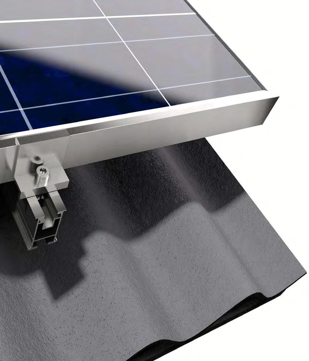
4 Fig. A Fig. B 1 Fig. A: At the fastening point, drill a hole into the corrugated eternit roofing and the wooden structure beneath. Make sure that you always select a wave crest as the installation point. For the M10 hanger bolt, you require a ø 7 mm drill bit for the wooden structure, and ø 13 mm for the eternit panel. For the M12 hanger bolt, use a ø 8 mm drill bit for the wooden structure, and ø 15 mm for the eternit panel. Then screw in the full threaded length of the hanger bolt. Please ensure that you adhere to the minimum anchoring depth of 8 cm (M10) or 10 cm (M12) respectively. For anchoring to the support structure, you should provide a distance between the hanger bolt and the edge of the purlin of at least 3 cm (M10) or 3,6 cm (M12) respectively. Once you have placed the hanger bolt, affix the EPDM sealing over the drilled hole with an M10/M12 fixing nut. Then, install the fast mounting plate between 2 additional nuts in such a manner, that a plane bearing surface for the mounting profiles is created, on which the mounting profiles can be placed stressless. Now fix the fast mounting plate by adjusting the two nuts at the head of the hanger bolt connection. Hint: It is strictly forbidden to install a PV system on an asbestos cement roof. 4 2 Fig. B: Insert the mounting profile in the preassembled fast mounting plate on the hanger bolt and align the mounting profiles. Afterwards tighten the allen screw to fix the connection. Please note:» Each mounting profile has to be fixed on minimum two roof fixation elements (e.g. hanger bolt).» The maximum mounting profile length should not exceed 15,0 m.» After 15,0 m, install an expansion joint of at least 5 cm.» The mounting profiles should have a maximum cantilever of 30 cm beyond the last roof fixation element.


5 3 Fig. C: To connect the mounting profiles insert the profile connector into the profiles. The mounting profiles should not be plugged together before they are at the installation site (e.g. the roof). Fig. C Please note: The connected mounting profiles should not be transported in vertical. 4 Fig. D Fig. E: End caps can be applied to the mounting profiles as optical finishing. Press them by hand in the end of the mounting profile at the required profile. Fig. E 5

 as well")

 ĀF ) ĀG 6 Fig.")

6 5 Additional information for double-layer systems: Mount the basis layer profiles according to the before mentioned installation steps on the roof fixation elements (e.g. hanger bolts). The orientation of the profiles could be horizontal (parallel to the ridge) as well as vertical (parallel to the rafter). Fig. F: Screw in the cross connector in the upper slot of the basis layer profile and screw in also the allen screw with the threaded plate in the upper slot. Fig. G: Align the cross connector and tighten the allen screw to fix it. ) ĀF ) ĀG 6 Fig. H: Insert the mounting profile in the cross connector and align the mounting profiles. Afterwards tighten the allen screw to fix the connection. Please note: The screw of the cross connector to fix the mounting profile should always be aligned in direction to the top (in direction to the ridge). ) ĀH 6


7 7 8 Fig. I: Place the first module with an edge distance of miniumum 3 cm on the mounting profiles. Insert the preassembled end clamps and tighten the allen screws. Fig. I Fig. J: For the fixation of the module on the other side, place another module on the mounting profiles beside the first and insert the preassembled middle clamps in between of the two modules. Align the modules and tighten the allen screws to fix them. Proceed in this manner until you have placed the last module of the row. Fix it with end clamps as described before. Fig. J Please note: The mounting areas prescribed by the manufacturer of your module can be found in the module data sheet. 7


8 PLEASE PAY ATTENTION TO THE FOLLOWING NOTES! We recommend, that you read the following information carefully, as it is of great importance when handling the product. Please also inform yourself of the safety regulations which pertain to the other system components. 8
9 SAFETY INFORMATION AND WARNINGS You should adhere to these instructions precisely, whenever working on the PV system. Installation, commissioning, maintenance and repairs may only be performed by appropriately qualified and authorized persons. Please observe the applicable regulations and safety instructions. You must observe the following accident prevention regulations:» BGV A 1 General regulations» BGV A 2 Electrical systems and equipment» BGV C 22 Construction work (personal fall protection equipment)» The trade association health and safety at work rules (BGR 203 Working on roofs) and DIN EN 516 Equipment for accessing roofs» The trade association regulations regarding work clothing and work safety You must adhere to the following DIN standards:» DIN General rules for all kinds of building works» DIN Roof covering and roof sealing works» DIN Metal construction and locksmith works» DIN 4102 Fire behaviour of building materials and building components Only authorized personnel may carry out work on systems of Alumero Systematic Solutions GmbH. The operator of the system has the following safety-related obligations:» Performance of regular annual maintenance work, e.g. inspection of cabling, bolt connections, and the roof skin.» The mounting system may only be installed by persons with suitable qualifications, technical skills, and knowledge of the fundamentals of mechanics.» It must be ensured that the assigned persons can assess the work allocated to them, and can identify possible dangers.» The installation instructions are part of the product, and must be available during installation.» It must be guaranteed that the installation instructions, and particularly the safety instructions, have been read and understood by the assigned personnel before installation.» The trade association regulations, the local work safety regulations and the technical regulations must be adhered to.» Suitable hoisting equipment and ladders are to be used for the installation work. No leaning ladders may be used.» It is necessary to arrange for a qualified construction engineer to assess the building s existing static loading characteristics with regard to the additional loads of a PV system.» Any general load reduction measures specified by Alumero Systematic Solutions GmbH (e.g. the need to clear snow, so as to limit the snow load) are to be observed. 9
10 WARRANTY / PRODUCT LIABILITY (EXCLUSION) The dimensioning information included in these instructions merely represents information gathered in practice. Binding structural calculations for the mounting system can be calculated with the software Alumero.Solar.Pro.Tool. As the installation company, you are responsible for correct execution of installation work. Alumero Systematic Solutions GmbH is not liable for the dimensioning information included in commercial system proposals. As installer, you are responsible for the mechanical durability of the interface connections mounted on the building s structure. In particular, this includes that these are leak-tight. The components of Alumero Systematic Solutions GmbH are designed for the expected loads and they are in compliance with the effective state of the art. For this purpose, you have to specify in writing all general technical framework conditions in the project documentation form (information on the support structure, snow load zone, building heights, wind loads, etc. ) when requesting information/ordering from Alumero Systematic Solutions GmbH. Alumero Systematic Solutions GmbH is not liable for incorrect handling of the installed parts. Any use close to the sea is excluded because of the increased risk of corrosion. NOTES ON ELECTRICAL INSTALLATION WORK Only if you are a qualified electrician, you may perform any electrical work. The applicable DIN standards, VDE regulations, VDEW guidelines, VDN guidelines, accident prevention regulations and the regulations of the local utility company are authoritative in this regard.» DIN VDE 0100 (Installation of high voltage systems with nominal voltages up to 1000 V)» VDEW guideline for parallel operation of domestic power-generation systems with the low voltage grid of the utility company» VDI 6012 sheet 2, guideline for decentralized energy systems in buildings: Photovoltaics» Leaflet for VDEW guideline Domestic power-generation systems on the low voltage grid» VDN guideline Domestic power-generation systems on the low voltage grid» DIN/VDEregulations, DIN/VDE 0100 Installing high voltage systems with grid voltages up to 1000 V, in particular VDE 0100, Part 410, Protection against direct and indirect contact (Direct current > 120 V, < 1000 V direct current) and the Accident prevention regulations of the commercial trade associations VBG4 Electrical systems and equipment» DIN VDE Selection and installation Earthing, protective conductors and equipotential bonding conductors» DIN VDE 0185 Installation of a lightning protection system and VDS 2010 Alumero Systematic Solutions GmbH grants a 2-year product guarantee on the service life and stability of the mounting systems, subject to correct handling, dimensioning in accordance with the static loading conditions, normal environmental conditions, and normal ambient conditions. This applies within the generally prevalent weather conditions and environmental conditions. Material and workmanship guarantee: Alumero Systematic Solutions GmbH grants a 10-year material and workmanship guarantee on the materials used. Consult the specific guarantee conditions for more detailed information. 10
11 IMPORTANT WARNINGS Solar modules generate electricity as soon as they are exposed to light. There is always a voltage present. The fully insulated plug contacts provide a level of contact protection but when dealing with solar modules, the following points must be observed:» Do not insert electrically conductive parts into the plugs or sockets.» Do not install solar modules and wiring using wet plugs or sockets.» Perform any work on cabling with extreme caution.» Do not carry out any electrical installation work in damp conditions.» Also with low lighting, very high direct voltages arise at the series connection of modules, which can be life-threatening upon contact. In particular, note the possibility of secondary damage in the event of electric shocks. Even when the unit is switched off, high contact voltages may still be present inside the inverter:» Be particularly careful when working on the inverter and the cables.» After switching off the inverter, it is essential to wait for the time interval specified by the manufacturer before beginning any further work to allow the high voltage components to discharge.» Please also observe the installation guidelines provided by the inverter manufacturer.» Check to see if all screw connections are tightened correctly.» Adhere to the specified torques.» Regardeless a verifiable static equilibrium, it is your responsibility to ensure before every installation that the product meets the local static requirements pursuant to DIN 1055.» DIN standard 1055 Actions on structures Part 1: Densities and weights of building materials, structural elements, stored materials Part 4: Wind loads Part 5: Snow load and ice load Part 100: Basis of structural design Safety concept and design rules» The mounting system is designed in accordance with DIN 4113 Aluminum constructions under predominantly static loading and DIN Steel structures; design and construction or the corresponding Eurocode EC1, EC3, EC9.» Ensure that the substructure, support structure and other affected layers (such as an insulation layer) have adequate load capacity (based on dimensions, condition and suitable material properties).» Make sure that the rainwater runoff is not impeded.» Pay attention to the physical construction aspects (e.g. possible condensation problems caused by penetration of insulating layers). When breaking a connected string of modules (e.g. when disconnecting the DC line from the inverter under load), a lethally strong electric arc can occur:» Never disconnect the solar generator from the inverter as long as it is connected to the mains. STANDARDS AND GUIDELINES All of the standards and guidelines listed here are published for and applicable to Germany. They are to be complied with in their current version. Outside of Germany, please also observe the corresponding national standards and guidelines. NOTES ON THE INSTALLATION OF MOUNTING SYSTEMS For installation in roof areas, you must adhere to the currently applicable structural engineering regulations, especially the requirements set out in the DIN standards and in the Regulations of the German Roofing Industry ( Regelwerk des Deutschen Dachdeckerhandwerks ). PRODUCT LIABILITY The technical documentation constitutes part of the product. Alumero Systematic Solutions GmbH is not liable for damages caused by noncompliance with the installation instructions, particularly the safety instructions, or caused by inappropriate use of the products. 11


12 CONGRATULATIONS, WELL DONE! Alumero Systematic Solutions GmbH Sonnenweg Seeham - Österreich T / F / alumero@alumero.at January 2013 CONTACT HEADQUARTER
TRAPEZOIDAL SHEET METAL RAIL LIFT/VARIO for trapezoidal sheet metal roofs
 Photovoltaic mounting systems Assembly Instructions TRAPEZOIDAL SHEET METAL RAIL LIFT/VARIO for trapezoidal sheet metal roofs 1 Table of contents 1 Introduction 1.1 Intended use 3 1.2 About the document
Conergy SolarFamulus II
 Conergy SolarFamulus II Installation manual www.conergy.com Table of Contents Table of Contents SolarFamulus II for universal use on flat roofs 1 Introduction 1 1.1 Short description 1 1.2 Intended use
TRAPEZOIDAL SHEET METAL RAIL
 Photovoltaic Mounting Systems Assembly Instructions TRAPEZOIDAL SHEET METAL RAIL Mounting system for roofing with trapezoidal sheet metal S:FLEX GmbH 09/2017 / design and engineering is subject to change
ST-AK 1/12. Photovoltaic Mounting Systems. Assembly Instructions. Mounting system for roofing with trapezoidal sheet metal
 Photovoltaic Mounting Systems Assembly Instructions ST-AK 1/12 Mounting system for roofing with trapezoidal sheet metal S:FLEX GmbH 09/2017 / design and engineering is subject to change 1 Index 1 Introduction
Mounting instructions. novotegra for trapezoidal metal - roof parallel
 Mounting instructions novotegra for trapezoidal metal - roof parallel I TABLE OF CONTENTS 1 Notes... 1 2 Maintenance of the mounting system... 3 3 novotegra for trapezoidal metal - roof parallel... 3 4
Mounting systems for solar technology
 Mounting systems for solar technology ASSEMBLY INSTRUCTIONS SPEEDRAIL system GB Table of contents TABLE OF CONTENTS THE COMPANY SAFETY REGULATIONS MATERIALS REQUIRED TOOLS REQUIRED ASSEMBLY 2 3 4 5 7 8
On-roof system Tau Installation manual
 On-roof system Tau Installation manual 810-0052 Table of Contents 1 Introduction 1 1.1 Short description 1 1.2 Intended use 1 1.3 Standards and guidelines 1 1.4 About these instructions 1 Tau The innovative
installation instructions English
 www.creotecc.com installation instructions English Safety instructions 04 General notes 07 Material & tool requirements 08 System overview 10 installation of HANGER BOLTS 12 Maintenance 23 04 INTENDED
Mounting instructions
 Mounting instructions novotegra for tile roofs top-fix I TABLE OF CONTENTS 1 Notes... 1 2 Maintenance of the mounting system... 3 3 novotegra for tile roofs... 3 4 System components, tools and equipment...
PITCHED ROOF. Photovoltaic Mounting Systems. Assembly Instructions. for roofing tiles, plain tiles and slate
 Photovoltaic Mounting Systems Assembly Instructions PITCHED ROOF for roofing tiles, plain tiles and slate S:FLEX GmbH 09/2017 / design and engineering is subject to change 1 Index 1 Introduction 1.1 Intended
00MK-MA0160-EN00. Mounting System ASSEMBLY INSTRUCTIONS. Little Plan and Little Plan Light systems, for corrugated sheet metal roof
 00MK-MA0160-EN00 Mounting System ASSEMBLY INSTRUCTIONS Little Plan and Little Plan Light systems, for corrugated sheet metal roof Rev.02 November 2014 Table of contents General instructions 2 General safety
INSTALLATION MANUAL AEROCOMPACT+ east/west
 INSTALLATION MANUAL AEROCOMPACT+ east/west IN. AE plus US 2015.1 2 INTRODUCTION Thank you for choosing the Aerocompact mounting system. Please read these instructions carefully before starting the installation
Radiant PV-RoofTopRac System Planning and Installation With Australia AS/NZS1170.2:2011 AMDT
 Radiant PV-RoofTopRac System Planning and Installation With Australia AS/NZS1170.2:2011 AMDT 2-2012 The PV-RoofTopRac System has been developed as a universal system for roof-mounting on pitched roofs.
Mounting systems for solar technology
 Mounting systems for solar technology ASSEMBLY INSTRUCTIONS CROSSRAIL TILT KIT 7 / 0 / 5 TILT FOR LOW-SLOPE AND STEEP-SLOPE ROOFS TABLE OF CONTENTS TABLE OF CONTENTS THE COMPANY SAFETY REGULATIONS MATERIALS
INSTALLATION INSTRUCTION AEROCOMPACT S5
 INSTALLATION INSTRUCTION AEROCOMPACT S5 Flat-roof mount for PV installations IN. AEs5 US 2014.1 the unbeatable flat-roof solution YOUR BIG ADVANTAGE + 25 years product warranty + Best price value available
Installation Instruction for DMEGC Photovoltaic Module
 Content 1. PURPOSE... 1 1.1 GENERAL TERM... 1 2. SAFETY PRECAUTIONS FOR SOLAR PV SYSTEM INSTALLATION... 3 3. INSTALLATION CONDITION... 4 3.1 INSTALLATION LOCATION AND WORKING CONDITIONS... 4 3.2 SELECTION
ON-ROOF ATTACHMENT FLAT COLLECTOR HELIOSTAR
 ON-ROOF ATTACHMENT FLAT COLLECTOR HELIOSTAR INSTALLATION INSTRUCTIONS ENERGY AND SANITARY SYSTEMS Installation requirements Generel requirements The on-roof attachment set is capable for installation of
Mounting System MCG 3.0 Membrane-Connected Glass. System description
 Mounting System MCG 3.0 Membrane-Connected Glass System description SUNOVA MCG 3.0 System Fields of application: Not suitable for: (please inquire for other SUNOVA systems) The SUNOVA MCG 3.0 system is
INSTALLATION INSTRUCTIONS ENGLISH
 INSTALLATION INSTRUCTIONS ENGLISH Safety instructions 04 General notes 07 Material & tool requirements 08 System overview 10 installation of CREODUR 11 Maintenance 22 04 INTENDED USE Creotecc mounting
Mounting System MCG 3.0 Membrane-Connected Glass. System description
 Mounting System MCG 3.0 Membrane-Connected Glass System description SUNOVA MCG 3.0 System Fields of application: Not suitable for: (please inquire for other SUNOVA systems) The SUNOVA MCG 3.0 system is
HELIOSTAR 252, 218 VERTICAL, FREE INSTALLATION
 HELIOSTAR 252, 218 VERTICAL, FREE INSTALLATION INSTRUCTION MANUAL ENERGY AND SANITARY SYSTEMS Installation requirements General requirements The free-standing installation set is to be used or installing
YINGLI SOLAR TWINMAX MODULES Installation and User Manual
 YINGLI SOLAR TWINMAX MODULES Installation and User Manual Revision Date Aug 3rd, 2016 Applicable for IEC certified products This manual applies to photovoltaic TwinMAX modules ( TwinMAX modules, also commonly
Radiant PV-Solar Tripod System Planning and Installation With Australia AS/NZS1170.2:2011 AMDT
 Radiant PV-Solar Tripod System Planning and Installation With Australia AS/NZS1170.2:2011 AMDT 2-2012 The PV-Solar Tripod System has been developed as a universal system for tilt solar panel roof-mounting
HELIOSTAR 252, 218 HORIZONTAL, FREE INSTALLATION
 HELIOSTAR 252, 218 HORIZONTAL, FREE INSTALLATION INSTALLATION INSTRUCTIONS ENERGY AND SANITARY SYSTEMS Installation requirements General requirements The free-standing installation set is to be used for
Installation instructions
 Installation instructions IBC AeroFix Date: 30-Jun-2015 1 Contents 0. Introduction... 3 01. Tool list... 4 02. General information, standards and regulations... 4 03. System variants... 8 04. Technical
installation instructions English
 www.creotecc.com installation instructions English Safety instructions 04 General notes 07 Material & tool requirements 08 System overview 10 installation of CREODUR 11 Maintenance 22 04 INTENDED USE
MANUAL. landscape orientation. portrait orientation. metal roof mounting system for solar panels METAL ROOF MOUNTING SYSTEM. Rev
 MANUAL METAL ROOF MOUNTING SYSTEM EN landscape orientation portrait orientation metal roof mounting system for solar panels ESDEC BV 2018 CONTENTS 1. Introduction 1 2. General installation conditions 1
Mounting System MCG 1.1 Membrane-Connected Glass. System description
 Mounting System MCG 1.1 Membrane-Connected Glass System description SUNOVA MCG 1.1 System Fields of application: Not suitable for: (please inquire for other SUNOVA systems) The SUNOVA MCG system is a lightweight
Radiant Solar Tripod Planning and Installation Guide V1.2 With Australia AS/NZS1170.2
 Radiant Solar Tripod Planning and Installation Guide V1.2 With Australia AS/NZS1170.2 The Solar Tripod System has been developed as a universal system for roof-mounting on flat roofs. The use of patented
Mounting instructions. novotegra for folded seam roof
 Mounting instructions novotegra for folded seam roof I TABLE OF CONTENTS 1 Notes... 1 2 Maintenance of the mounting system... 3 3 novotegra for folded seam roof... 3 4 System components, tools and work
ifix INSTALLATION MANUAL PV flat roof installation system Version
 ifix PV flat roof installation system INSTALLATION MANUAL Version 2012-09-06 ifix Installation Manual Version 2012-09-06 Seite 1 Table of contents Table of contents... 1 Special characteristics of ifix...
Installation instructions
 Installation instructions IBC AeroFix Version 17.01 Date: 27-Jun-2017 1 Contents 0. Introduction...3 01. Tool list...4 02. General information, standards and regulations...4 03. System variants...8 04.
Mounting systems for solar technology
 Mounting systems for solar technology ASSEMBLY INSTRUCTIONS S-DOME SYSTEM GB TABLE OF CONTENTS TABLE OF CONTENTS THE COMPANY SAFETY REGULATIONS MATERIALS REQUIRED TOOLS REQUIRED ASSEMBLY 3 4 5 8 9 Table
Clenergy ezrack SolarRoof Code-Compliant Planning and Installation With Australia AS/NZS1170
 Clenergy ezrack SolarRoof Code-Compliant Planning and Installation With Australia AS/NZS1170 The ezrack has been developed as a universal system for roof-mounting on pitched roofs. The use of patented
Mounting systems for solar technology
 Mounting systems for solar technology SSEMLY INSTRUCTIONS SINGLEHOOK 1.1 SINGLEHOOK VRIO STINLESS STEEL ROOF HOOKS WITH DPTER G GENERL SFETY INFORMTION Please note that our general mounting instructions
SoliTek PV Modules INSTALLATION MANUAL
 SoliTek PV Modules INSTALLATION MANUAL Version: 16 10 14 According to: IEC 61215 IEC 61730 For: SOLID PRO 300-310 W p SOLID PRO 250-260 W p SOLID PRO 150-160 W p Thank you for choosing SoliTek panels.
INSTALLATION INSTRUCTIONS TRI-STAND East-West. energy for a better world. Mounting system for PV systems with east-west orientation on flat roofs
 energy for a better world INSTALLATION INSTRUCTIONS TRI-STAND East-West Mounting system for PV systems with east-west orientation on flat roofs Quick and easy installation Aerodynamically optimized No
Mounting systems for solar technology
 Mounting systems for solar technology ASSEMBLY INSTRUCTIONS S-DOME SYSTEM GB TABLE OF CONTENTS TABLE OF CONTENTS THE COMPANY SAFETY REGULATIONS MATERIALS REQUIRED TOOLS REQUIRED ASSEMBLY 2 3 4 5 8 9 Table
Tindo Karra. Installation and Specifications Manual. Introduction
 Tindo Karra Installation and Specifications Manual Introduction Thank you for choosing a Tindo Solar Module. Background to our name TINDO Tindo is a word from the Kaurna warra Aboriginal language which
INSTALLATION INSTRUCTIONS ENGLISH
 INSTALLATION INSTRUCTIONS ENGLISH Safety instructions 04 General notes 07 Material & tool requirements 08 System overview 10 installation of ALUTEC 12 Maintenance 27 04 INTENDED USE Creotecc mounting
Mounting systems for solar technology ASSEMBLY INSTRUCTIONS. SpeedRail System.
 Mounting systems for solar technology ASSEMBLY INSTRUCTIONS SpeedRail System www.k2-systems.com Content TTTools overview 3 TTGeneral safety information 4 TTGuidelines 5 TTComponents: Portrait assembly
LEICHTmount TM EU 2.0 S 5 /10 /15
 Photovoltaic Mounting Systems Assembly Instructions LEICHTmount TM EU 2.0 S 5 /10 /15 Flat Roof Mounting System for PV Installations IN. LMEU S US 2015.1 inquiry@sflex.com www.sflex.com S:FLEX 06/2014
a-si/μcsi Tandem Module Installation Manual Macsun Solar Energy Technology Co., Limited Applied to MS-SDXX
 a-si/μcsi Tandem Module Installation Manual Macsun Solar Energy Technology Co., Limited 2014.1.20 Applied to MS-SDXX 1. 2. 3. 4. 5. CONTENT PURPOSE... 2 WARNING... 2 SCOPE... 2 RESPONSIBILITY... 2 INSTALLATION...
ASSEMBLY INSTRUCTIONS RESIDENTIAL SOLUTION CROSSRAIL GROUND MOUNT SYSTEM USA
 ASSEMBLY INSTRUCTIONS RESIDENTIAL SOLUTION CROSSRAIL GROUND MOUNT SYSTEM USA TABLE OF CONTENTS TABLE OF CONTENTS SAFETY REGULATIONS MATERIALS REQUIRED ASSEMBLY ENGINEERING DRAWINGS TERMS AND CONDITIONS
MANUAL MOUNTING SYSTEM FOR BITUMEN / EPDM
 MANUAL MOUNTING SYSTEM FOR BITUMEN / EPDM EN mounting system for uninsulated pitched roof Bitumen / EPDM for solar panels portrait / landscape setup ESDEC BV 2015 TABLE OF CONTENT 1. Introduction 1 2.
PRR. Flush Mount Racking System. Installation Manual
 PRR Flush Mount Racking System Installation Manual Release, September 2014 Table of Contents 1. Introduction 1.1 Product Overview 1.2 About This Manual 1.3 Product Liability 1.4 Standards Compliance 1.5
Flat roof for the loading-optimized elevation (adhesive system)
") Mounting systems Flat roof for the loading-optimized elevation (adhesive system) FLAMONT Production I Professional wholesale Adhesive mounting without roof penetration no weight easy to install low price
Mounting systems Flat roof for the loading-optimized elevation (adhesive system) FLAMONT Production I Professional wholesale Adhesive mounting without roof penetration no weight easy to install low price
MOUNTING SYSTEM FOR PITCHED ROOF WITH TILES. mounting system for pitched roof with tiles for solar panels in landscape setup. Rev
 MANUAL EN MOUNTING SYSTEM FOR PITCHED ROOF WITH TILES mounting system for pitched roof with tiles for solar panels in landscape setup ESDEC BV 2016 TABLE OF CONTENT 1. Introduction 1 2. General installation
MOUNTING SYSTEM FOR SOLAR POWER SYSTEMS PLANNING AND DESIGN
 Instruction sheet MOUNTING SYSTEM FOR SOLAR POWER SYSTEMS PLANNING AND DESIGN Original instruction sheet for installers www.solarworld.com Proven quality simply clever With the for solar power systems,
Infix ProLine Installation manual
 Infix ProLine Installation manual 80-0007 Table of contents Introduction. Overview. Intended use. Standards and technical directives.4 About this manual Theta Only the sun gets in Safety. Basic safety
Mounting systems for solar technology
 Mounting systems for solar technology ASSEMBLY INSTRUCTIONS S-Dome Small system GB Table of contents TABLE OF CONTENTS THE COMPANY SAFETY REGULATIONS MATERIALS REQUIRED TOOLS REQUIRED ASSEMBLY 2 3 4 5
MRac Tile Roof Installation Guide
 MRac Tile Roof Installation Guide Tile Interface 117HA AS/NZS1170.2 Content 1. Product Introduction-------------------------------------------------------P2 2. Installation Tools& Components---------------------------------------P3
Installers Guide. Item
 Installers Guide Item 17060-01 Required tools and fixings Electric drill (non-impact setting) T-25 Torq bit (wedge type) Pozi head drill bit Tape measure Pencil/pen Hammer Tin snips Angle grinder (to cut
PV-ezRack Trapezoidal Installation Guide V2.0
 PV-ezRack Trapezoidal Installation Guide V2.0 Introduction Clenergy s PV-ezRack Trapezoidal is the most simple and cost-effective flat roof mounting system suitable for trapezoid metal sheet roof. The
Installation Guide EcoFoot5D High Density 5-Degree Ballasted Racking System Document No. ES10560
 Installation Guide Installation Guide EcoFoot5D High Density 5-Degree Ballasted Racking System Document No. ES10560 Rev 1.0, September 2017 Sales: 740-249-1877 Sales@EcolibriumSolar.com Field Support:
PV Mounting System 2703 SERIES 200 UL GROUND MOUNT SYSTEM. SnapNrack Residential PV Mounting Systems Code Compliant Installation Manual
 PV Mounting System 2703 SERIES 200 UL GROUND MOUNT SYSTEM SnapNrack Residential PV Mounting Systems Code Compliant Installation Manual Series 200 UL Introduction Series 200 UL Introduction SnapNrack Series
User instructions for photovoltaic modules 60Pxxx-V 60Mxxx-V 72Pxxx-V 72Mxxx-V 60Pxxx 60Mxxx 72Pxxx 72Mxxx
 F r e n c h P h o t o v o l t a i c M o d u l e s M a n u f a c t u r e r 20 15 July User instructions for photovoltaic modules 60Pxxx-V 60Mxxx-V 72Pxxx-V 72Mxxx-V 60Pxxx 60Mxxx 72Pxxx 72Mxxx 1 Introduction
Aurora Genmounts Install LT Installation Manual
 Aurora Genmounts Install LT Installation Manual TABLE OF CONTENTS 1.0 INTRODUCTION 2.0 PRODUCT OVERVIEW 3.0 TECHNICAL SPECS 4.0 INSTALLER RESPONSIBILITY 5.0 SITE SELECTION 6.0 TOOLS REQUIRED 7.0 COMPONENT
MOUNTING SYSTEMS APPLICATIONS OVERVIEW
 MOUNTING SYSTEMS APPLICATIONS OVERVIEW Catalogue Verion June 2013 TRITEC MOUNTING SYSTEMS: OVERVIEW OF APPLICATIONS I. Pitched Roof: Roof-Top 1. Tiles, shingles and corrugated panels 1.1 TRI-STAND on tiles
Installation and Users Manual
 Installation and Users Manual *Please read carefully. This document is binding for any warranty case. * Any installed PV system less than 500m from coastline, please refer to the Near-coast installation
PV-ezRack SolarMatrix Pro
 PV-ezRack SolarMatrix Pro Planning and Installation Guide Contents 1 Introduction 2 2 Installation Tools & Components 4 3 Installation Instruction 6 4 Service 10 1. Introduction PV-ezRack SolarMatrix Pro
IEC Installation Guide for SERAPHIM Photovoltaic Module
 SUSA [InstallationGuide] 2016.11_V1.0 IEC Installation Guide for SERAPHIM Photovoltaic Module Table of Contents 2 Purpose of this guide General safety Handling safety Installation safety Fire safety 5
EJOT Solar Fastenings. Installation Manual
 EJOT Solar Fastenings Installation Manual Setscrew DIN 913 M10 x Lg A2 with internal hex drive SW5 Locknut DIN 985 M10 Plain washer M10 Hexagon nut M10 Precise defined depth (control) stop Washer E16/8
EASY ROOF FLAT PV FIXING SYSTEM FOR FLAT ROOF
 INS-IN02-180726 Version 1.0-24-04-18 EASY ROOF FLAT PV FIXING SYSTEM FOR FLAT ROOF For all LANDSCAPE-orientated framed modules ASSEMBLY INSTRUCTIONS Document validated by ENQUETE TECHNIQUE NOUVELLE No.
SystemFS. SystemFS product sheet. Generation 6
 SystemFS Generation 6 No ground sealing Extremely short mounting time Maximum level of pre-fabrication Optimally aligned system components High durability due to optimal material combinations Best possible
ifix Installation Manual PV flat roof mounting system english Version May 1st, 2018
 ifix PV flat roof mounting system Installation Manual english Version May 1st, 2018 voestalpine Automotive Components Schwäbisch Gmünd GmbH & Co. KG www.voestalpine.com/ac Table of Contents ifix Installation
mounting systems applications overview
 mounting systems applications overview catalogue version January 2015 tritec mounting systems: overview of applications i. pitched roof: roof-top 1. Tiles, shingles and corrugated panels 1.1 TRI-STAND
GROUND MOUNT INSTALLATION MANUAL
 GROUND MOUNT INSTALLATION MANUAL Contents DISCLAIMER 1 CHECKLIST 2 1. ERECT BASe 3 2. CONNECT PIPES 3 3. PLACE RAILS 4 4. SECURE LUGS 4 5. CLAMP MODULES 5 DIAGONAL BRACES (OPTIONAL) 6 UNDER CLAMPS (OPTIONAL)
Installation and Operation Manual
 Installation and Operation Manual Solarion M210T General Information This document contains important information for the installation of Solarion M210T solar modules from OC3 AG. Please read this document
SystemFS. SystemFS product sheet. Generation 6
 SystemFS Generation 6 No ground sealing Extremely short mounting time Maximum level of pre-fabrication Application for patent filed at at the German patent office Optimally aligned system components High
KRIWAN Wind Sensors. Operating Instructions Accessories and Application Information
 KRIWAN Wind Sensors Operating Instructions Accessories and Application Information Contents Contents General information... 4 Manufacturer...4 Storage information...4 Supplementary documents...4 List of
SECURE. UNIVERSAL. MOUNTING. Tilt Kit Installation Manual
 SECURE. UNIVERSAL. MOUNTING Tilt Kit Installation Manual 1.0 INTRODUCTION... 3 2.0 KITS / PRODUCT RANGE... 4 2.1 Leg Kits... 4 2.2 Rail Kits... 4 3.0 PREPARATION FOR INSTALLATION... 5 3.1 Applications...
PV-ezRack SolarTerrace III-A Installation Guide V1.2
 PV-ezRack SolarTerrace III-A Installation Guide V1.2 CONTENT 1. Introduction...2 2. Tools & Components...3 3. Installation Guide. 10 4. Service..12 Clenergy Australia 11/20 Duerdin St, Clayton VIC 3168
Inspection Guide for PV Systems in One- and Two- Family Dwellings (For Rooftop Photovoltaic Systems meeting the Standard Plan)
") TOOLKIT DOCUMENT #7 Inspection Guide for PV Systems in One- and Two- Family Dwellings (For Rooftop Photovoltaic Systems meeting the Standard Plan) This document has two sections. Neither section is all-inclusive
TOOLKIT DOCUMENT #7 Inspection Guide for PV Systems in One- and Two- Family Dwellings (For Rooftop Photovoltaic Systems meeting the Standard Plan) This document has two sections. Neither section is all-inclusive
Installation manual ValkTriple EN-UK
 Van der Valk Solar Systems TRCKING ND FIXED SOLR MOUNTING SYSTEMS Installation manual ValkTriple EN-UK Version 08 EN General user instructions Solar mounting systems Congratulations on buying a Van der
Architectural Roof and Wall Products Guide Specifications
 Architectural Roof and Wall Products Guide Specifications Western States Metal Roofing 901 W. Watkins St. Phoenix, AZ 85007 PH: 602-495-0048 FX: 602-261-7726 FORMED METAL WALL PANELS This Guide Specification
INSTALLATION GUIDE Sika SolarMount 1 Exposition East West
 Exposition East West CONTENTS 1 Notes on the Sika SolarMount 1 system (Exposition East West) for PV solar arrays 3 2 Setting up on site 3 3 Required Tools for mounting Sika SolarMount 1 to Sika roofing
USER MANUAL FOR MOLDS MOLDS FOR THE PRODUCTION OF CONCRETE ELEMENTS
 USER MANUAL FOR MOLDS MOLDS FOR THE PRODUCTION OF CONCRETE ELEMENTS [incl. Installation Instructions for EG Machinery Directive 2006 42 EG Annex VI for partly completed machinery] MADE IN GERMANY Product
moment Engineering + Design Warwick Avenue, Suite #C5 Fairfax, VA Phone: Web:
 CrossRail48SConnector RE: CrossRail48SConnectorEvaluation DesignReferenceDocuments MinimumDesignLoadsforBuildingsandOtherStructures 2010AluminumDesign MetalCurtainWallFasteners Overview Methods&DesignParameters
Mounting systems for solar technology ASSEMBLY INSTRUCTIONS. S-Dome 2.0 System.
 Mounting systems for solar technology ASSEMBLY INSTRUCTIONS S-Dome 2.0 System www.k2-systems.com Content T Tools overview 3 T General safety information 4 T Required Materials 6 T Assembly 9 T Notes QUALITY
Festoon Manual Heavy Duty C-Track
 Festoon Manual Heavy Duty C-Track 966300.3 Heavy Duty C-Track Manual CONDUCTIX INCORPORATED The technical data and images which appear in this manual are for informational purposes only. NO WARRANTIES,
MANUAL. portrait set-up. landscape set-up. ClickFit Evo mounting system for sloping roofs with roof tiles for solar panels
 MANUAL MOUNTING SYSTEMS FOR SLOPING ROOFS WITH ROOF TILES EN portrait set-up landscape set-up ClickFit Evo mounting system for sloping roofs with roof tiles for solar panels ESDEC BV 2017 CONTENTS 1. Introduction
TallSlateTM Grandee Installation Manual
 TallSlateTM Grandee Installation Manual PLEASE READ THIS GUIDE COMPLETELY BEFORE INSTALLING OR USING THE SOLAR ELECTRIC MODULES Disclaimer of Liability...2 General Information...2 General Safety...2 TM
ValkPitched - Bitumen
 ValkPitched - itumen Installation manual Use in combination with the Project Report of the ValkPVplanner Version 01 EN Van der Valk Solar Systems Solar Mounting Systems Please note Table of contents This
SolarStyl BIPV New Building Integrated Photovoltaic System August V13 Page 0
 SolarStyl BIPV New Building Integrated Photovoltaic System 2010 August V13 Page 0 By ArcelorMittal Stainless & Nickel Alloys SolarStyl Frame for BIPV Systems To simplify photovoltaic roof and facade design.
INTERSOL MOUNTING SYSTEMS
 INTERSOL MOUNTING SYSTEMS PRODUCT CATALOGUE 2012 Das ist die Rubrik HIGHEST QUALITY PHOTOVOLTAICS. MOUNTING SYSTEMS FROM DONAUER SOLARTECHNIK. Donauer Solartechnik is one of the largest photo voltaic system
Installation Instruction photovoltaic modules E-PV 250W on the flat roof or fundation 10/2013 Get acquainted before the installation.
 Installation Instruction photovoltaic modules E-PV 250W on the flat roof or fundation 10/2013 Get acquainted before the installation. 1. General information Lightning Protection System In case of LPS we
PV-ezRack SolarTerrace II
 PV-ezRack SolarTerrace II Code-Compliant Planning and Installation Complying with AS/NZS1170.2:2011 Amdt 3 2013 Contents 1 Introduction 2 2 Installation Tools & Components 3 3 Installation Guide 7 4 Service
Mounting systems for solar technology ASSEMBLY INSTRUCTIONS. D-Dome System.
 Mounting systems for solar technology ASSEMBLY INSTRUCTIONS D-Dome System www.k2-systems.com Content TTTools overview 3 TTGeneral safety information 4 TTRequired Materials 6 TTAssembly 9 TTNotes 17 QUALITY
Industrial flue gas probes. Instruction manual
 Industrial flue gas probes Instruction manual 2 1 Contents 1 Contents 1 Contents... 3 2 Safety and the environment... 4 2.1. About this document... 4 2.2. Ensure safety... 4 2.3. Protecting the environment...
2019 V1 SERAPHIM DG PHOTOVOLTAIC MODULE JIANGSU SERAPHIM PHOTOVOLTAIC SYSTEM CO. LTD. ADDRESS: JIANGSU CITY OF CHANGZHOU PROVINCE WANG ZHEN HENG
 2019 V1 SERAPHIM DG PHOTOVOLTAIC MODULE JIANGSU SERAPHIM PHOTOVOLTAIC SYSTEM CO. LTD. ADDRESS: JIANGSU CITY OF CHANGZHOU PROVINCE WANG ZHEN HENG ROAD NO. 1-2. TELEPHONE: +86-519-88776028 FAX: +86-519-88786181
Benefits in Speed and Logistics using the RL System. snapnrack.com
 Benefits in Speed and Logistics using the RL System snapnrack.com Agenda About SnapNrack Overview of Residential Solar Mounting Systems Benefits of railless systems What you should look for in a railless
Mounting systems for solar technology ASSEMBLY INSTRUCTIONS. D-Dome 2.0 System.
 Mounting systems for solar technology ASSEMBLY INSTRUCTIONS D-Dome 2.0 System www.k2-systems.com Content TTTools overview 3 TTGeneral safety information 4 TTRequired Materials 6 TTAssembly 9 TTNotes 16
Platform stair lift PLG7
 Platform stair lift PLG7 ORIGINAL-user manual Part 2: Assembly Instruction English Version 2.00 ASCENDOR GMBH Drautendorf 48 4174 Niederwaldkirchen Austria Tel.: +43 7231 40040 Fax: +43 7231 40040-590
Solcellspaket - Poly (4.2 kwp Jinko 265W Poly) System Plan. Created with Solar-Planit by Mikael Johansson Futura Energi AB in Simrishamn.
 System Plan. Created with Solar-Planit by Mikael Johansson Futura Energi AB in Simrishamn.") Solcellspaket - Poly (4.2 kwp Jinko 265W Poly) System Plan Created with Solar-Planit by Mikael Johansson Futura Energi AB in 272 36 Simrishamn. Project YOUR PHOTOVOLTAIC SPECIALIST Company Contact Address
Solcellspaket - Poly (4.2 kwp Jinko 265W Poly) System Plan Created with Solar-Planit by Mikael Johansson Futura Energi AB in 272 36 Simrishamn. Project YOUR PHOTOVOLTAIC SPECIALIST Company Contact Address
ValkPitched - Clamp. Installation manual. Van der Valk Solar Systems. Solar Mounting Systems. Version 17 EN
 ValkPitched - Clamp Installation manual Version 17 EN Van der Valk Solar Systems Solar Mounting Systems Please note Table of contents This manual is not project specific. This manual is not legally binding.
Installation instructions for. Wall Mounting Frame C M298 - M311 - M313 - M314 - M316. Version: 1.0 Date:
 Installation instructions for Wall Mounting Frame C9900 - M298 - M311 - M313 - M314 - M316 Version: 1.0 Date: 2008-09-19 General Notes Table of contents 1. 2. 3. General Notes 2 Notes on the documentation
PRB. Flush Mount Racking System. Installation Manual
 PRB Flush Mount Racking System Installation Manual Released 5th April 2015 TABLE OF CONTENTS 1. INTRODUCTION 1.1 Product Overview 1.2 About This Manual 1.3 Product Liability 1.4 Standards Compliance 1.5
Mounting systems for solar technology ASSEMBLY INSTRUCTIONS. S-Dome System.
 Mounting systems for solar technology ASSEMBLY INSTRUCTIONS S-Dome System www.k2-systems.com Content TTTools overview 3 TTGeneral safety information 4 TTRequired Materials 6 TTAssembly 9 TTNotes 17 QUALITY