FIRE TEST REPORT FP 5663
|
|
|
- Cory Bishop
- 5 years ago
- Views:
Transcription


1 1222 Moonshine Road Judgeford RD1 Porirua 5381 New Zealand T F branz@branz.co.nz FIRE TEST REPORT FP 5663 FIRE RESISTANCE OF PIPE PENETRATIONS IN A 60 MINUTE PLASTERBOARD WALL CLIENT Snap Fire Systems Pty Ltd Building A 1343 Wynnum Road Tingalpa, 4173 QLD Australia This Laboratory is accredited by International Accreditation New Zealand (IANZ). The tests reported herein have been performed in accordance with the laboratory s scope of accreditation. PROJECT NUMBER: ISSUE DATE: PAGE: FT March of 34
2 TEST SUMMARY Objective To determine the fire resistance of pipe penetration sealing systems in accordance with AS Fire Resistance tests of elements of building construction: Section 10 Service Penetrations and Control Joints, with reference to AS Test sponsor Snap Fire Systems Pty Ltd Unit Redland Bay Rd, Capalaba, 4157 QLD Australia Description of test specimen The test wall consisted of 16 mm thick Fyrestop plasterboard secured over 64 mm deep steel studs. The overall dimensions of the wall measured 2,200 x 1,000 mm. The wall was fitted with 10 pipe penetration collars which were placed over pre-drilled holes. The pipes ranged in diameter from 20 mm to 110 mm OD and the materials included Pex-Al-Pex, PVC and HDPE. All pipes were fitted with Snap pipe collars comprising a galvanised steel sleeve with an intumescent wrap inserted in the annular space between the pipe and the sleeve to both the exposed and unexposed faces of the wall. Date of test 28 th July 2015 FP March of 34
3 Test results The fire resistance in minutes, in accordance with AS , of 10 pipe penetrations and their sealing systems in a plasterboard wall, was as follows: Specimen No. Collar Pipe Size (Nom, mm) Integrity, min Insulation, min FRL 1 32Gas Gas Pex 20 91NF 86 -/90/ R PVC U* 25 91NF 73 -/90/ R Electrical Conduit 25 91NF 63 -/90/ R PVC U 40 91NF 61 -/90/ R HDPE 40 91NF 68 -/90/ R PVC U 50 91NF 75 -/90/ R PVC U 65 91NF 73 -/90/ R PVC U 80 91NF 76 -/90/ R PVC U NF 66 -/90/ R HDPE NF 62 -/90/60 * AS/NZS 1477: PVC pipes and fittings for pressure applications. NF = No failure for the duration of the test. The test standard requires the following statements to be included: "The results of these fire tests may be used to directly assess fire hazard, but it should be recognized that a single test method will not provide a full assessment of fire hazard under all fire conditions. "This report details methods of construction, the test conditions and results obtained when the specific element of construction described herein was tested following the procedure outlined in this standard. Any significant variations with respect to size, constructional details, loads, stresses, edge or end conditions, other than those allowed under the field of direct application in the relevant test method, is not covered by this report. FP March of 34
4 Because of the nature of fire resistance testing and the consequent difficulty in quantifying the uncertainty of measurement of fire resistance, it is not possible to provide a stated degree of accuracy of the result." LIMITATION The results reported here relate only to the item/s tested. TERMS AND CONDITIONS This report is issued in accordance with the Terms and Conditions as detailed and agreed in the BRANZ Services Agreement for this work. FP March of 34
5 FP March of 34
6 CONTENTS SIGNATORIES... 8 DOCUMENT REVISION STATUS TEST PROCEDURE Integrity Insulation DESCRIPTION OF TEST SPECIMEN General Penetration details Pipe support spacing Pipe specification Penetration seal details TEST CONDITIONS AND RESULTS General Furnace temperature measurement Furnace control Pressure measurement Specimen temperature measurement Specimen insulation Observations Integrity CONCLUSION PERMISSIBLE VARIATIONS FIGURES Figure 1: Specimen 1 collar for gas pipe, Gas Figure 2: Specimen 2 and 3 collars, 32R...12 Figure 3: Specimens 4 to 6 collars, 50R...12 Figure 4: Specimen 7 collar, 63R...12 Figure 5: Specimen 8 collar, 65-80R...13 Figure 6: Specimens 9 and 10 collar, 110R...13 Figure 7: Test specimen showing location of penetrations...14 Figure 8: Furnace temperature...15 Figure 9: Accuracy of furnace control...16 Figure 10: Furnace pressure...17 Figure 11: Specimen 1 temperature rise...18 FP March of 34
7 Figure 12: Specimen 2 temperature rise...18 Figure 13: Specimen 3 temperature rise...19 Figure 14: Specimen 4 temperature rise...19 Figure 15: Specimen 5 temperature rise...20 Figure 16: Specimen 6 temperature rise...20 Figure 17: Specimen 7 temperature rise...21 Figure 18: Specimen 8 temperature rise...21 Figure 19: Specimen 9 temperature rise...22 Figure 20: Specimen 10 temperature rise...22 Figure 21: Maximum temperature rises on all 10 specimens...23 Figure 22: Unexposed surface temperature rise...23 TABLES Table 1: Specimen pipe details...10 Table 2: Pipe collars and intumescent...11 Table 3: Specimen Insulation failures...24 Table 4: Observations...24 Table 5: Specimen Integrity failures...27 PHOTOS Photo 1: Pre-test unexposed face...30 Photo 2: Pre-test exposed face...31 Photo 3: Penetration 1, left to right, unexposed, exposed and unexposed post test 32 Photo 4: Penetration 2, left to right, unexposed, exposed and unexposed post test 32 Photo 5: Penetration 3, left to right, unexposed, exposed and unexposed post test 32 Photo 6: Penetration 4, left to right, unexposed, exposed and unexposed post test 32 Photo 7: Penetration 5, left to right, unexposed, exposed and unexposed post test...32 Photo 8: Penetration 6, left to right, unexposed, exposed and unexposed post test Photo 9: Penetration 7, left to right, unexposed, exposed and unexposed post test...33 Photo 10: Penetration 8, left to right, unexposed, exposed and unexposed post test...33 Photo 11: Penetration 9, left to right, unexposed, exposed and unexposed post test...33 Photo 12: Penetration 10, left to right, unexposed, exposed and unexposed post test...33 Photo 13: Exposed face after test...34 FP March of 34

8 SIGNATORIES Author P. C. R. Collier Senior Fire Testing Engineer Reviewer P. Chapman Senior Fire Testing Engineer IANZ Approved Signatory DOCUMENT REVISION STATUS ISSUE NO. DATE ISSUED DESCRIPTION 1 19 March 2016 Initial Issue REPORT NUMBER: ISSUE DATE: PAGE: FP March of 34 THE LEGAL VALIDITY OF THIS REPORT CAN ONLY BE CLAIMED ON PRESENTATION OF THE COMPLETE SIGNED PAPER REPORT.
9 1. TEST PROCEDURE The test was conducted in accordance with AS Methods for fire tests on building materials, components and structures, Part 4 Fire-resistance tests of elements of construction, Section 10 Service penetrations and control joints, with reference to AS , Service penetrations and control joints, Section 3.1 Fire Resistance Testing. In accordance with the test standard the fire resistance of the specimen is the time, expressed in minutes, to failure under one or more of the following criteria. 1.1 Integrity Failure shall be deemed to occur when cracks, fissures or other openings develop through which flames or hot gases can pass. Failure occurs; a) If flaming on the unexposed surface of the specimen is sustained for longer than 10 seconds; or b) When flames and/or hot gases cause flaming or glowing of the cotton fibre pad. 1.2 Insulation Failure shall be deemed to occur when any of the relevant thermocouples attached to the unexposed face of the test specimen rises more than 180K above the initial temperature. 2. DESCRIPTION OF TEST SPECIMEN 2.1 General The vertical separating element consisted of a steel framed wall nominally 2,200 mm high x 1,000 mm wide. One layer of 16 mm thick Firestop plasterboard was installed on the exposed and unexposed face of the wall. The framing consisted of nominal 64 mm x 0.5 mm base metal thickness (BMT) steel studs at nominally 510 mm centres with nogs at intervals of firstly 400 mm, then 325 mm centres from the top of the wall. The framing was screwed together with 6g x 12 mm pan head TEK screws. The plasterboard was screwed fixed to the steel frame with wallboard screws measuring 6g x 32 mm. There were a total of 10 pipe specimens, all the pipe specimens passed through the wall perpendicular to the face. All dimensions are nominal unless stated otherwise. A drawing of the layout is included in this report as Figure 7. All pipes protruded a minimum of 430 mm into the furnace and at least 2,040 mm from the unexposed face. All pipes were plugged with kaowool on the exposed face and were open on the unexposed face. FP March of 34
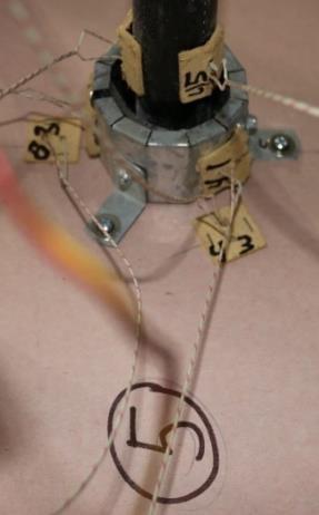
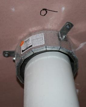
10 2.2 Penetration details Pipe support spacing All pipes were supported at nominal distances from the wall of 800 and 1,800 mm with pipe clamps which were in turn attached to a steel frame Pipe specification Table 1 lists the nominal and measured pipe dimensions and pipe designation details for the pipe penetrations. Table 1: Specimen pipe details Specimen no. Hole in wall size (mm) Nominal size of pipe Diameter (actual) x wall thickness (mm) Pipe Material Pipe (Unex/Ex) x 2.6 Gas Pex Open/capped x 2.0 PVC U* Open/capped x 1.8 Electrical Conduit Open/capped x 2.3 PVC U Open/capped x 3.3 HDPE Open/capped x 2.4 PVC U Open/capped x 3.2 PVC U Open/capped x 3.4 PVC U Open/capped x 3.5 PVC U Open/capped x 5 HDPE Open/capped * AS/NZS 1477: PVC pipes and fittings for pressure applications Penetration seal details The pipe collar details are presented in Table 2 and photographs of the collars in Figure 1 to Figure 6. The collars were fixed to each side of the plasterboard wall with hollow wall anchors designated as HWA4SL by Powers Fasteners and washers measured as 15 x 1.2 x 5.5 mm diameter hole. FP March of 34
 Product Code Intumescent Material (# x width x thickness) 1 20 Gas32 2 x (60 x 4) 2 25")
 8 80 65-80R 2 x (60 x 4) 9 100 110R 3 x (60 x 4) 10 110 110R 3 x (60 x 4) Figure 1:")
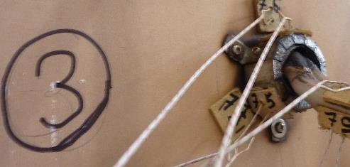
11 Table 2: Pipe collars and intumescent Specimen no. Pipe Size (Nom mm) Product Code Intumescent Material (# x width x thickness) 1 20 Gas32 2 x (60 x 4) R 2 x (25 x 4) R 2 x (25 x 4) R 2 x (60 x 4) R 2 x (60 x 4) R 2 x (60 x 4) R 2 x (60 x 4) R 2 x (60 x 4) R 3 x (60 x 4) R 3 x (60 x 4) Figure 1: Specimen 1 collar for gas pipe, Gas32 FP March of 34


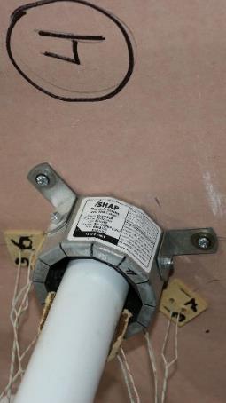
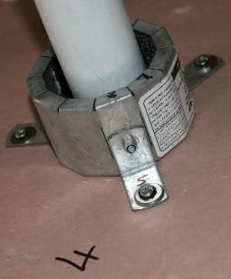
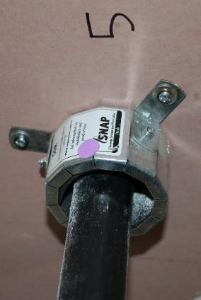
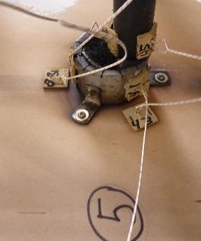
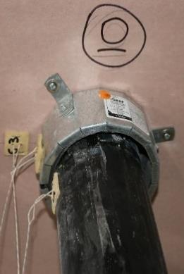
12 Figure 2: Specimen 2 and 3 collars, 32R Figure 3: Specimens 4 to 6 collars, 50R Figure 4: Specimen 7 collar, 63R FP March of 34


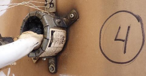
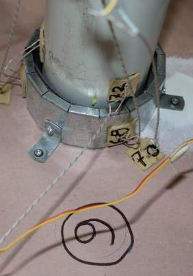
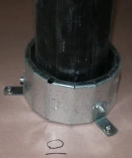
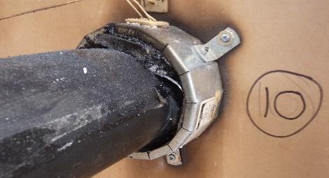
13 Figure 5: Specimen 8 collar, 65-80R Figure 6: Specimens 9 and 10 collar, 110R FP March of 34
14 Figure 7: Test specimen showing location of penetrations t/c No mm hole No mm hole No mm hole No mm hole 325 No mm hole No mm hole No mm hole No mm hole 285 No mm hole No mm hole 285 t/c 73 ` Steel support frame FP March of 34
15 Temperature ( C) 3. TEST CONDITIONS AND RESULTS 3.1 General The specimen was tested on the 28 July 2015 at BRANZ laboratories, Judgeford, New Zealand, in the presence of a representative of the client. The ambient temperature at the beginning of the test was 13 C. The wall containing the specimens was placed against the vertical pilot furnace and the temperature and pressure conditions were controlled to the limits defined in AS Furnace temperature measurement Temperature measurement within the furnace was made using four mineral insulated metal sheathed (MIMS) chromel-alumel thermocouples uniformly distributed in a vertical plane approximately 100 mm from the exposed face of the specimen. The furnace thermocouples were connected to a computer controlled data acquisition system which recorded the temperatures at 15 second intervals. Figure 8 shows the furnace temperature curve and the permitted upper and lower limits in accordance with AS : Figure 8: Furnace temperature Mean Standard Std -100 Std Time (minutes) FP March of 34
16 Percentage (%) 3.3 Furnace control The percentage deviation of the area of the furnace mean temperature from the standard temperature/time curve complied with the test standard for the duration of the test. Figure 9 shows the percentage deviation of the mean furnace temperature from the Standard curve. Figure 9: Accuracy of furnace control Actual Allowable Time (minutes) 3.4 Pressure measurement The furnace pressure was controlled to be 15 Pa at the mid height of the lowest penetration at 650 mm, as defined in the test standard. The differential pressure was monitored using a micromanometer connected to a computer controlled data acquisition system which recorded the pressure at 15 second intervals. Figure 10 shows the pressure measured at the 900 mm probe during the test, where the target pressure was 17 Pa. FP March of 34
17 Pressure (Pa) Figure 10: Furnace pressure Probe Target Limit Time (minutes) The furnace pressure complied with the test standard for the entirety of the test. 3.5 Specimen temperature measurement The temperature on the unexposed face of the penetrations were measured with chromel-alumel thermocouples attached to the specimens. The arrangement consisted of thermocouples placed as specified in clause 10.5 of the test standard AS For each specimen, thermocouples were placed on the unexposed surface of the plasterboard element at 25 mm from the collar, on the collar and on the pipes at a distance 25 mm from the collar. These three locations were in pairs with thermocouples fitted to the top and side of the penetrations, making a total of six thermocouples per penetration. Two additional thermocouples were placed on the unexposed surface of the wall clear of any of the penetrations. Figure 11 to Figure 21 show the temperature rise for each specimen. The temperature rise on the unexposed side of the wall is shown in Figure 22 where the positions of thermocouples 33 and 73 are shown in Figure 7. FP March of 34
18 Temperature Rise (K) Temperature Rise (K) Figure 11: Specimen 1 temperature rise K criteria on collar top on collar side wall 25mm left wall 25mm right pipe 25mm top pipe 25mm side Time (minutes) Figure 12: Specimen 2 temperature rise K criteria on collar top on collar side wall 25mm left wall 25mm right pipe 25mm top pipe 25mm side Time (minutes) FP March of 34
19 Temperature Rise (K) Temperature Rise (K) Figure 13: Specimen 3 temperature rise K criteria on collar top on collar side wall 25mm left wall 25mm right pipe 25mm top pipe 25mm side Time (minutes) Figure 14: Specimen 4 temperature rise K criteria on collar top on collar side wall 25mm left wall 25mm right pipe 25mm top pipe 25mm side Time (minutes) FP March of 34
20 Temperature Rise (K) Temperature Rise (K) Figure 15: Specimen 5 temperature rise K criteria on collar top on collar side wall 25mm above wall 25mm side pipe 25mm top pipe 25mm side Time (minutes) Figure 16: Specimen 6 temperature rise K criteria on collar top on collar side wall 25mm above wall 25mm side pipe 25mm top pipe 25mm side Time (minutes) FP March of 34
21 Temperature Rise (K) Temperature Rise (K) Figure 17: Specimen 7 temperature rise K criteria on collar top on collar side wall 25mm above wall 25mm side pipe 25mm top pipe 25mm side Time (minutes) Figure 18: Specimen 8 temperature rise K criteria on collar top on collar side wall 25mm above wall 25mm side pipe 25mm top pipe 25mm side Time (minutes) FP March of 34
22 Temperature Rise (K) Temperature Rise (K) Figure 19: Specimen 9 temperature rise K criteria on collar top on collar side wall 25mm above wall 25mm side pipe 25mm top pipe 25mm side Time (minutes) Figure 20: Specimen 10 temperature rise K criteria on collar top on collar side wall 25mm above wall 25mm side pipe 25mm top pipe 25mm side Time (minutes) FP March of 34
23 Temperature Rise (K) Temperature Rise (K) Figure 21: Maximum temperature rises on all 10 specimens K criteria Specimen 1 Specimen 2 Specimen 3 Specimen 4 Specimen Specimen 6 Specimen 7 Specimen 8 Specimen 9 Specimen Time (minutes) Figure 22: Unexposed surface temperature rise K criteria Time (minutes) FP March of 34
24 3.6 Specimen insulation Table 3: Specimen Insulation failures Specimen No. Time (minutes) until which failure occurred (T>180K) Location of Insulation Failure 1 86 On wall 25 mm from collar 2 73 On collar 3 63 On collar 4 61 On pipe wall 25 mm from collar 5 68 On collar 6 75 On wall 25 mm from collar 7 73 On wall 25 mm from collar 8 76 On wall 25 mm from collar 9 66 On wall 25 mm from collar, and on collar On collar 3.7 Observations Observations related to the Integrity performance of the specimens were at the times stated in minutes and seconds. U = Observations from the unexposed face. E = Observations from the exposed face. Table 4: Observations Time mm:ss Test face 1:29 U 1:55 U 2:16 U 2:20 U 2:36 U 3:30 U Observation Smoke was being emitted from the ends of the pipes of penetrations No.1, 2 and 7. A significant volume of smoke was being emitted from the end of the pipe of penetration No. 7. Smoke was being emitted from the collars on penetrations No. 2 and 5. Smoke was being emitted from the end of the pipe of penetration No.6. Smoke was being emitted from the end of the pipe of penetration No.8. A significant volume of smoke was being emitted from the ends of the pipes of penetrations No. 8 and 9. FP March of 34
25 Time mm:ss Test face 4:15 U 5:00 U 7:00 U 8:00 U 10:30 U 20:00 U 24:00 U 27:00 U 29:00 U 35:00 U 37:41 U 40:00 U 40:50 U 44:00 U Observation Smoke was being emitted from the end of the pipe of penetration No.10. Smoke has stopped being emitted from the end of the pipes of penetrations No.1, 2 and 6. There was a significantly reduced volume smoke emitted from the end of the pipe of penetrations No. 8 and 9. A significant volume of smoke was being emitted from the end of the pipe of penetration No.10. The majority of pipes have closed off. There was a small volume of smoke being emitted from the ends of the pipes of penetration No. 8, 9 and 10. Where the pipes exit the wall of penetrations No. 6, 8 and 9 the pipe were sagging slightly. There was a small volume of steam being emitted from around the collars of penetrations No. 2, 5 and 9 where they were attached to the wall. Smoke has stopped being emitted from the end of the pipes of penetrations No.1 through 9, and a significantly reduced volume of smoke was being emitted from the end of the pipe of penetration No.10. A small volume of smoke was being emitted from the collars on penetrations No. 2, 5 and 9. Smoke was being emitted from the pipes of penetration No. 2, 6, 7 and 9. The pipe of penetration No. 2 was further sagging where it exits the collar. Smoke and steam were being emitted from the ends of the pipes of penetrations No. 2, 5, 6, 7, 8 and 9. Pipes were sagging over a length of approximately 300 mm outwards from the collars on penetrations No. 2, 6, 8 and 9. Smoke was being emitted from the ends of the pipes of penetrations No. 2, 3, 6, 7, 8 and 9. A significant volume of smoke was pulsating from the collar around the pipe of penetration No. 10. There was a small volume of smoke being emitted from the end of the pipes of penetrations No. 2, 3, 7, 8, 9 and 10. The pipe of penetration No. 3 was sagging where it exited the wall. Smoke was being emitted from between the collar and pipe of penetration No. 10. Smoke has stopped being emitted from the end of the pipes of penetrations No. 1, 4 and 10. Smoke was being emitted from the ends of the pipes of penetrations No. 3, 7, 8 and 9. A small volume of smoke was being emitted from the ends of the pipes of penetrations No. 2 and 6. FP March of 34
26 Time mm:ss Test face 45:00 U 46:50 U 53:00 55:50 U U 56:30 U 59:00 U 60:00 U 68:00 U 71:00 72:30 74:00 74:50 U U U U Observation Where the pipe of penetration No. 3 exits the collar the pipe had largely collapsed within collar. Smoke was still being emitted from the end of the pipe. The pipe of penetration No. 3 was pulling away from the wall. The thermocouples on the pipe were approximately 50 mm from the end of the collar. Smoke was being emitted from the end of the pipes of penetration No. 2, 3, 5, 6, 7, 8, 9 and 10. Smoke was being emitted from between the pipe and collar of penetration No. 6, 9 and 10. The thermocouple on the top of the pipe of penetration No. 10 had detached from the pipe. The pipe was starting to collapse just past the collar with intumescent expanding into the void. The smoke being emitted from the end of the pipes of penetrations No. 6, 7 8 and 9 had turned yellow in color. A reduced volume of smoke was being emitted from the ends of the pipes of penetrations No. 1, 2, 3, 4 and 10. The pipe of penetration No. 10 has melted back about 50 mm from the collar and the intumescent had sealed the hole. The pipes of penetrations No. 5, 6, 9 and 10 were starting to sag where they exited the collar and smoke/steam was being emitted from between the pipe and collar. A significant volume of yellowish smoke was continuing to be emitted from the ends of the pipes of penetrations No. 7, 8 and 9. The pipe of penetration No. 9 had softened and the intumescent was oozing out of the collar. At the wall the pipe of penetration No. 9 had largely collapsed and intumescent from the unexposed face collar was expanding outward. The pipes of penetrations No. 4 and 8 had largely collapsed where they exited the wall and the pipe of penetration No. 7 was sagging downward. Intumescent was starting to fall away from the collar of penetration No. 9 as it pushed the pipe away from the collar. There was also a corresponding reduction in the volume of smoke being emitted from the end of the pipe. A red glow was visible in the center of the intumescent of penetration No. 9. A cotton pad was applied over the red glow of penetration No. 9. Minor discoloration of the pad had occurred, but no Integrity failure occurred. The paper facing around the lower penetrations on the left hand side of the wall was starting to discolour. FP March of 34
27 Time mm:ss Test face 77:00 U 79:00 U 80:43 U 89:20 U Observation 91:00 Test stopped. Smoke was being emitted from the ends of the pipes of penetrations No. 2, 4, 6, and 8. A small volume of smoke was being emitted from the end of the pipe of penetrations No. 3. The pipe on penetration No. 4 had sagged and was almost dropping off. There was a small volume of smoke being emitted from the ends of the pipes of penetrations No. 4, 6 and 8. The intumescent of penetration No. 9 continued to expand and the red glow was no longer visible in the middle of the opening. Smoke was being emitted from the ends of the pipe of penetration No. 4. The pipe on penetration No. 8 had sagged at the collar and the intumescent had closed off the pipe. A cotton pad was applied to penetration No. 9. No discolouration of the pad no Integrity failure occurred Integrity Integrity failures were recorded as follows: Table 5: Specimen Integrity failures Specimen No. Time (minutes) which Integrity failure occurred 1 91 NF 2 91 NF 3 91 NF 4 91 NF 5 91 NF 6 91 NF 7 91 NF 8 91 NF 9 91 NF NF FP March of 34
28 4. CONCLUSION The fire resistance in minutes, in accordance with AS , of the 10 pipe penetrations and their sealing systems in a plasterboard wall was as follows: Specimen No. Collar Pipe Size (Nom, mm) Integrity, min Insulation, min FRL 1 32Gas Gas Pex 20 91NF 86 -/90/ R PVC U* 25 91NF 73 -/90/ R Electrical Conduit 25 91NF 63 -/90/ R PVC U 40 91NF 61 -/90/ R HDPE 40 91NF 68 -/90/ R PVC U 50 91NF 75 -/90/ R PVC U 65 91NF 73 -/90/ R PVC U 80 91NF 76 -/90/ R PVC U NF 66 -/90/ R HDPE NF 62 -/90/60 * AS/NZS 1477: PVC pipes and fittings for pressure applications. NF = No failure for the duration of the test. The test standard requires the following statements to be included: "The results of these fire tests may be used to directly assess fire hazard, but it should be recognized that a single test method will not provide a full assessment of fire hazard under all fire conditions. "This report details methods of construction, the test conditions and results obtained when the specific element of construction described herein was tested following the procedure outlined in this standard. Any significant variations with respect to size, constructional details, loads, stresses, edge or end conditions, other than those allowed under the field of direct application in the relevant test method, is not covered by this report. FP March of 34
29 Because of the nature of fire resistance testing and the consequent difficulty in quantifying the uncertainty of measurement of fire resistance, it is not possible to provide a stated degree of accuracy of the result." 5. PERMISSIBLE VARIATIONS In accordance with AS :2005 clause 10.11, the permissible variations that are relevant to the tested penetration systems reported in FP 5663 are as follows PERMISSIBLE VARIATIONS TO THE TESTED SPECIMEN General The results of the fire test contained in the test report are directly applicable without reference to the testing authority to similar constructions where one or more of the changes set out in Clauses to have been made Separating elements Results obtained for sealing systems in various types of masonry and concrete construction may be applied as follows: (c) Results obtained from framed wall systems may be applied to the performance of a system in concrete, masonry or solid gypsum blocks of greater or equal thickness to that of the tested prototype. The reverse does not apply. (d) Results obtained from framed wall systems may be applied to similar walls having studs of the same material with sizes greater than the tested prototype. (e) Results obtained from a prototype test may be applied to framed wall systems of similar construction but having thicker facings of the same material applied to the studs Plastic pipes General In addition to the requirements of clause , test results may be directly applied to the masonry and concrete elements thicker than the tested prototype when installed in accordance with Figure Services not perpendicular to the fire separation Penetrations not perpendicular to the plane of the element are acceptable provided that the fire-stopping system has similar exposure and dimensions to the tested prototype. FP March of 34

30 PHOTOS Photo 1: Pre-test unexposed face FP March of 34

31 Photo 2: Pre-test exposed face FP March of 34


32 Photo 3: Penetration 1, left to right, unexposed, exposed and unexposed post test Photo 4: Penetration 2, left to right, unexposed, exposed and unexposed post test Photo 5: Penetration 3, left to right, unexposed, exposed and unexposed post test Photo 6: Penetration 4, left to right, unexposed, exposed and unexposed post test Photo 7: Penetration 5, left to right, unexposed, exposed and unexposed post test FP March of 34


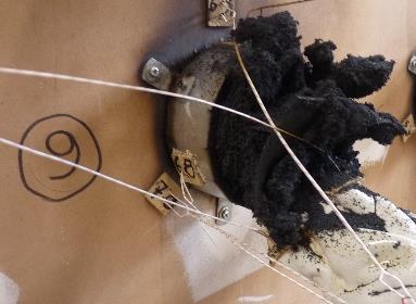
33 Photo 8: Penetration 6, left to right, unexposed, exposed and unexposed post test Photo 9: Penetration 7, left to right, unexposed, exposed and unexposed post test Photo 10: Penetration 8, left to right, unexposed, exposed and unexposed post test Photo 11: Penetration 9, left to right, unexposed, exposed and unexposed post test Photo 12: Penetration 10, left to right, unexposed, exposed and unexposed post test FP March of 34

34 Photo 13: Exposed face after test FP March of 34
PROJECT NUMBER: ISSUE DATE: EXPIRY DATE: PAGE: FT March March of 28
 1222 Moonshine Road Judgeford RD1 Porirua 5381 New Zealand T +64 4 237 1170 F +64 4 237 1171 branz@branz.co.nz www.branz.co.nz BRANZ Type Test FR 5740-TT [2016] FIRE RESISTANCE OF A LOAD BEARING TIMBER
FIRE ASSESSMENT REPORT FAR 3929 ISSUE 4
 1222 Moonshine Road Judgeford RD1 Porirua 5381 New Zealand T +64 4 237 1170 F +64 4 237 1171 branz@branz.co.nz www.branz.co.nz FIRE ASSESSMENT REPORT FAR 3929 ISSUE 4 FIRE RESISTANCE OF SNAP FIRE SYSTEMS
FIRE ASSESSMENT REPORT FAR 2251 ISSUE 2
 1222 Moonshine Road Judgeford RD1 Porirua 5381 New Zealand T +64 4 237 1170 F +64 4 237 1171 branz@branz.co.nz www.branz.co.nz FIRE ASSESSMENT REPORT FAR 2251 ISSUE 2 FIRE RESISTANCE OF ECO BLOCK WALL
Comparison between the SNAP Prototype Collar Tested in FP 4428 and the SNAP LP100R Collar. R. W. Causer Fire Testing Engineer
 FAR 3722 Comparison between the SNAP Prototype Collar Tested in FP 4428 and the SNAP LP100R Collar Author: R. W. Causer Fire Testing Engineer Reviewer: P. C. R. Collier Senior Fire Engineer Contact: BRANZ
Comparison Between the SNAP Prototype Collar Tested in FP 4428 and the SNAP LP100R Collar. R. W. Causer Fire Testing Engineer
 FAR 3722 Issue 3 Comparison Between the SNAP Prototype Collar Tested in FP 4428 and the SNAP LP100R Collar Author: R. W. Causer Fire Testing Engineer Reviewer: P. Bano-Chapman Senior Fire Testing Engineer
BRE Global Test Report
 BRE Global Test Report Ad-hoc fire resistance test on a galvanised steel Tunnel Ventilation Damper employing procedures and criteria from BS 476: Part 20 : 1987. Prepared for: Betec Cad Industries Date:
FIRE-RESISTANCE TEST ON FIRE COLLARS PROTECTING A CONCRETE SLAB PENETRATED BY SERVICES
 FIRE-RESISTANCE TEST ON FIRE COLLARS PROTECTING A CONCRETE SLAB PENETRATED BY SERVICES Report number FSP 1568 CSIRO job number SP3610 Date of issue 11 JANUARY 2013 Client ITW AUSTRALIA PTY LTD. Trading
ASSESSMENT REPORT. EWFA Report No: Report Sponsor: 3M New Zealand 94 Apollo Drive, Rosedale Auckland, New Zealand
 ASSESSMENT REPORT The fire resistance performance of 3M Plastic Device protecting the various, PP, PE and ABS plastic pipes penetrating walls and floors and tested in accordance with AS1530.4-2005 and
Property of Cooks Plumbing Supplies
 ASSESSMENT REPORT Assessment of the fire resistance performance of various diameter EZIPEX and pipes protected with Fireban One mastic or Hilti Firestop Intumescent sealant CP611A in wall systems when
TEST REPORT. Fire resistance load-bearing test of a 136mm thick Ozone Panels wall system tested in accordance with AS
 TEST REPORT Fire resistance load-bearing test of a 136mm thick Ozone Panels wall system tested in accordance with AS 1530.4 2005. EWFA Report No: 2758400 Report Sponsor: Ozone Panels Level 31, 367 Collins
Title: WF Report No: Prepared for: International Petroleum Products Ltd Bradwell Hall Bradwell-On-Sea Essex CMO 7HX. Date: 24 th August 2015
 Exova Warringtonfire Holmesfield Road Warrington WA1 2DS United Kingdom T : +44 (0) 1925 655 116 F : +44 (0) 1925 655 419 E : warrington@exova.com W: www.exova.com Title: The fire resistance performance
Title: WF Report No: Prepared for: Alstrong Enterprises India (PVT) Limited E-40/3, Okhla Industrial Area, New Delhi, India Date: 15 th June 2015
 Limited E-40/3, Okhla Industrial Area, New Delhi, India Date: 15 th June 2015") Exova Warringtonfire Holmesfield Road Warrington WA1 2DS United Kingdom T : +44 (0) 1925 655 116 F : +44 (0) 1925 655 419 E : warrington@exova.com W: www.exova.com Title: A fire resistance test performed
Exova Warringtonfire Holmesfield Road Warrington WA1 2DS United Kingdom T : +44 (0) 1925 655 116 F : +44 (0) 1925 655 419 E : warrington@exova.com W: www.exova.com Title: A fire resistance test performed
LOW PROFILE PIPE COLLARS
 LOW PROFILE S The low profile pipe collars are designed to be installed in concrete, brick or masonry fire rated walls and floors, and fire rated plasterboard walls. The Allproof pipe collars consist of
LOW PROFILE PIPE COLLARS
 LOW PROFILE S The low profile pipe collars are designed to be installed in concrete, brick or masonry fire rated walls and floors, and fire rated plasterboard walls. The Allproof pipe collars consist of
Test Report: Fire resistance test in accordance with BS EN :1999 on a nonloadbearing. incorporating Scolmore Doubled Switched electrical sockets
 Test Report: Fire resistance test in accordance with BS EN 1364-1:1999 on a nonloadbearing wall incorporating Scolmore Doubled Switched electrical sockets Prepared for: Scolmore International Limited,
PASSIVE FIRE PROTECTION PRODUCTS
 OCTOBER 2016 PASSIVE FIRE PROTECTION PRODUCTS www.allproof.com CONTENTS FIRE TESTING 1 ADVANCED INTUMESCENT 2 ALLPROOF INTUMESCENT TECHNOLOGY: 2 LOW PROFILE S 3 CONCRETE SLAB TEST RESULTS: 4 FLOOR WASTE
Likely fire performance of a loadbearing framed wall system lined with FireCrunch MBE-10 boards with cavity insulation
 INFRASTRUCTURE TECHNOLOGIES Likely fire performance of a loadbearing framed wall system lined with FireCrunch MBE-10 boards with cavity insulation Assessment Report Author: Brett Roddy Report number: FCO
PASSIVE FIRE PROTECTION PRODUCTS
 AUGUST 2018 PASSIVE FIRE PROTECTION PRODUCTS www.allproof.com CONTENTS FIRE TESTING 1 ADVANCED INTUMESCENT 2 ALLPROOF INTUMESCENT TECHNOLOGY: 2 LOW PROFILE S 3 CONCRETE SLAB TEST RESULTS: 4 FLOOR WASTE
Likely fire performance of AFS Logicwall systems
 INFRASTRUCTURE TECHNOLOGIES Likely fire performance of AFS Logicwall systems Assessment Report Author: Brett Roddy Report number: FCO-3084 Date: 3 October 2014 Client: CSR Structural Systems Pty Limited
Fire Hazard Properties of Eco- Block Wall Systems
 FSR 698 Fire Hazard Properties of Eco- Block Wall Systems Author: E. Soja Senior Fire Engineer Reviewer: C.A. Wade Principal Scientist Contact: BRANZ Limited Moonshine Road Judgeford Private Bag 50908
FIRE RESISTANCE TESTS OF BRICK VENEER / WOOD FRAME WALLS J. GREGG BORCHELT
 FIRE RESISTANCE TESTS OF BRICK VENEER / WOOD FRAME WALLS J. GREGG BORCHELT Vice President Engineering and Research Brick Industry Association Reston, VA United States of America JOHN SWINK Regional Engineer
REGULATORY INFORMATION REPORT
 REGULATORY INFORMATION REPORT The fire resistance performance of Hilti Flexible Firestop Foam CFS-F FX / CP 660 protecting cable and cable conduit penetrations in walls and concrete floors if tested in
Testing, calibrating, advising REGULATORY INFORMATION REPORT
 REGULATORY INFORMATION REPORT Fire-resistance test of various bundles of cables and pipes penetrating a 124mm Fyrchek plasterboard wall protected with BOSS Fyreboxes in accordance with AS1530.4 2014 EWFA
BRE Global Test Report
 BRE Global Test Report BS 8414-1:2015 + A1:2017 test on ventilated façade system with Kingspan (K15) thermal insulation and ACM panels Prepared for: Date: 18 January 2017 Mitsubishi Chemical Corporation
PROJECT NUMBER: ISSUE DATE: PAGE: ST October of 7
 1222 Moonshine Road Judgeford RD1 Porirua 5381 New Zealand T +64 4 237 1170 F +64 4 237 1171 branz@branz.co.nz www.branz.co.nz TEST REPORT ST1044 SHEAR TESTS OF ROCKCOTE AAC WALL CAVITY SYSTEMS CLIENT
TEST REPORT. Bushfire resistance test of an external wall system to BAL A40 in accordance with AS EWFA Report No:
 TEST REPORT Bushfire resistance test of an external wall system to BAL A40 in accordance with AS1530.8.1-2007 EWFA Report No: 38031900.1 Report Sponsor: Ullrich Aluminium PO BOX 246 Carole Park QLD 4300
BRE Global Assessment Report
 BRE Global Assessment Report An assessment of the fire performance of Suresnap Fire Collars fitted around plastic pipes penetrating concrete floors against the adopted criteria of BS 476: Part 20: 1987
REGULATORY INFORMATION REPORT
 REGULATORY INFORMATION REPORT The fire resistance performance of walls and floors penetrated by electrical cables and metal pipes protected by 3M CP 2WB+ Sealant if tested in accordance with AS130.4-200
REGULATORY INFORMATION REPORT. An assessment of the fire resistance of CSR Hebel external wall panels if tested in accordance with AS
 REGULATORY INFORMATION REPORT An assessment of the fire resistance of CSR Hebel external wall panels if tested in accordance with AS1530.4-2005. EWFA Report No: RIR 24648-07 Report Sponsor: CSR Panel Systems
CS-195+ Composite Sheet FR Board
 CS-195+ Composite Sheet FR Board Durable, Steel-lined Fire-Rated Board for up to 4 hours fire protection Tested to AS1530.4, EN1366 and UL Listed Technical Data Sheet a product Light. Strong. Durable.
FIRE TEST REPORT FH 5636
 1222 Moonshine Road Judgeford RD1 Porirua 5381 New Zealand T +64 4 237 1170 F +64 4 237 1171 branz@branz.co.nz www.branz.co.nz FIRE TEST REPORT FH 5636 CONE CALORIMETER TEST AND NZBC ACCEPTABLE SOLUTIONS
HILTI CFS-SL / CP 653 / SPEED SLEEVE / FIRESTOP SLEEVE FIRE RATED COLLARS. Product. Scope. Building Regulations. Appraisal No.
 HILTI CFS-SL / CP 653 / SPEED SLEEVE / FIRESTOP SLEEVE FIRE s Technical Assessments of products for building and construction. Hilti (New Zealand) Limited P O Box 112-030 Penrose Auckland 1642 Tel: 0800
FIRE RATING MATERIAL FIXING NOTES
 FIRE RATING MATERIAL FIXING NOTES FIRE RATING MATERIAL FIXING NOTES... 1 External Wall Systems... 2 Non load bearing steel stud walls... 3 LOAD-BEARING STEEL STUD WALLS... 3 NON LOAD-BEARING TIMBER STUD
ASSESSMENT REPORT. The fire resistance performance of UltraMgO - Partition 20 Party Wall System if tested in accordance with AS1530.
 ASSESSMENT REPORT The fire resistance performance of UltraMgO - Partition 20 Party Wall System if tested in accordance with AS1530.4-2014 EWFA Report No: RIR 46975500.2 Report Sponsor: Fireproof Cladding
OBJECTIVE TEST ASSEMBLY
 OBJECTIVE The ASTM E 119 test method is intended to evaluate the duration for which a building element will contain a fire, or retain its structural integrity, or display both properties dependent upon
ASSESSMENT REPORT. EWFA Report No: b 3. Report Sponsor: Timberwood Panels Pty Ltd National Blvd Campbellfield VIC 3061
 ASSESSMENT REPORT The Group Number and Average Specific Extinction Area of OSB Timber nominated by the test sponsor as Timberwood Panels OSB Light, an uncoated oriented strand board wall and ceiling lining
FIREFLY FR FRL-/60/60 MULTI-SERVICE BLOCK. TBA Firefly Head Office P.O. BOX 52 Laidley QLD, 4341 Australia
 TBA Protective Technologies Australia Head Office Unit 12, 8 Leighton Place Hornsby, NSW, 2077 TBA Firefly Head Office P.O. BOX 52 Laidley QLD, 4341 Australia TBA Textiles Pty Ltd ABN: 44 084 489 529 31
REGULATORY INFORMATION REPORT
 REGULATORY INFORMATION REPORT The fire resistance performance of walls and floors penetrated by electrical cables and metal pipes protected by 3M CS195+ Composite Sheet, if tested in accordance with AS1530.4-2005
P.O. Box ZN Bleiswijk Brandpuntlaan Zuid NZ Bleiswijk The Netherlands
 P.O. Box 554 2665 ZN Bleiswijk Brandpuntlaan Zuid 16 2665 NZ Bleiswijk The Netherlands +31 88 3473 723 nederland@efectis.com Determination of the fire resistance according to EN 1364-1:1999 and FprEN 1364-1:2014
3M CS-195+ Composite Sheet Product Description
 Product Data Sheet 3M Product Description 3M Fire Barrier is a one-part composite system comprised of four components. The heart of the system is an organic/ inorganic, fire-resistive elastomeric sheet.
EUROPEAN ORGANISATION FOR TECHNICAL APPROVALS
 E TA TECHNICAL REPORT Fire Resistance Tests for Cavity Barriers TR 31 Edition October 2008 EUROPEAN ORGANISATION FOR TECHNICAL APPROVALS EOTA TECHNICAL REPORT TR 031 Fire Resistance Tests for Cavity Barriers
System No. C-AJ-8133
 System No. C-AJ-8133 March 09, 2011 F Ratings - 1, 1-1/2, 2 and 3 Hr (See Item 2) T Ratings - 0, 1/2, 3/4, 1, 1-1/2, 2 and 3 Hr (See Item 2) 1. Floor or Wall Assembly Min 4-1/2 in. (114 mm) thick reinforced
P.O. Box ZN Bleiswijk Brandpuntlaan Zuid NZ Bleiswijk The Netherlands
 P.O. Box 554 2665 ZN Bleiswijk Brandpuntlaan Zuid 16 2665 NZ Bleiswijk The Netherlands +31 88 3473 723 nederland@efectis.com Determination of the fire resistance according to EN 1364-1:1999 and FprEN 1364-1:2014
Fire Test Report. Test Number 1243 Dated 22 September Prepared for:
 SPECIALIST VENTILATION SERVICES Ltd Unit 11A, Greencroft Industrial Park Annfield Plain, Stanley, County Durham, DH9 7YB Tel: 01207 529333 Fax: 01207 529444 E-mail: sales@specialistventilation.com Fire
3M Fire Barrier Sealant IC 15WB+
 3M Technical Data Sheet 3M Fire Barrier Sealant IC 15WB+ The 3M Fire Barrier Sealant IC 15WB+ is a latex sealant designed for use as a one-part fire, smoke, noxious gas and water resistant sealant. In
Guardian Fire Testing Laboratories, Inc. Phone: ; Fax: Wenonah Terr. (Office) Lab Phone & Fax:
 Lab Phone & Fax:") GUARDIAN Page 1 of 12 FIRE TESTING LABORATORIES, INC. Testing & Listing Field Labeling Engineering & Consulting Services Guardian Fire Testing Laboratories, Inc. Phone: 716 835 6880; Fax: 716 835 5682
GUARDIAN Page 1 of 12 FIRE TESTING LABORATORIES, INC. Testing & Listing Field Labeling Engineering & Consulting Services Guardian Fire Testing Laboratories, Inc. Phone: 716 835 6880; Fax: 716 835 5682
TEST REPORT FIRES-FR AUNE. Single side-hung lift landing semiautomatic door, thermally insulated with polyurethane
 TEST REPORT Single side-hung lift landing semiautomatic door, thermally insulated with polyurethane This is an electronic version of a test report which was made as a copy of test report officially issued
REPORT NUMBER: SAT-005 ORIGINAL ISSUE DATE: September 14, 2012 REVISED DATE: N/A
 TEST REPORT REPORT NUMBER: 100595243SAT-005 ORIGINAL ISSUE DATE: September 14, 2012 REVISED DATE: N/A EVALUATION CENTER 16015 Shady Falls Road Elmendorf, TX 78112 Phone: (210) 635-8100 Fax: (210) 635-8101
LISTING INFORMATION OF International Fireproof Technology Inc. - Joint Systems SPEC ID: 43848
 LISTING INFORMATION OF International Fireproof Technology Inc. - Joint Systems SPEC ID: 43848 International Fireproof Technology Inc. 17528 Von Karman Avenue Irvine, CA 92614 This report is for the exclusive
REGULATORY INFORMATION REPORT. EWFA Report No: Report Sponsor:
 REGULATORY INFORMATION REPORT The Fire Resistance Performance of Hilti CP606 protecting linear joints and gap seals in walls when tested in accordance with AS1530.4-2014 and assessed with AS4072.1-2005
REGULATORY INFORMATION REPORT
 REGULATORY INFORMATION REPORT An assessment of the fire resistance performance of a 150mm thick concrete floor penetrated by upvc plastic pipes and floor wastes protected by a Hilti CP 680 110/4 S + CP
ASSESSMENT REVIEW. Review of assessment report BWA and Regulatory Information Report RIR
 ASSESSMENT REVIEW Review of assessment report BWA 23260-00 and Regulatory Information Report RIR 23260-00 The fire resistance performance of walls and floors penetrated by electrical cables protected by
3M Fire Barrier Mouldable Putty
 3M Technical Data Sheet 3M Fire Barrier The 3M Fire Barrier consists of a synthetic elastomer designed for use as a one part, intumescent fire resistive putty used to restore the integrity of fire rated
ASTM E Fire Tests of Building Construction and Materials* Protective Structures, Ltd. Bullet-Resistant FRP Panel
 ASTM E119-98 Fire Tests of Building Construction and Materials* Protective Structures, Ltd. Bullet-Resistant FRP Panel Project No. 16410-108710 ONE-HOUR FIRE RESISTANCE TEST OF A NONBEARING STEEL STUD
BRE Global Ltd Watford, Herts WD25 9XX. d+b facades (UK) Ltd. The Packway, Larkhill, Salisbury, SP4 8PY. Customer Services
 Ltd. The Packway, Larkhill, Salisbury, SP4 8PY. Customer Services") BRE Global Test Report BS 8414-1:2015 + A1:2017 test on d+b facades rain screen cladding system with 100mm-thick Rockwool insulation and aluminium cassette panels. Prepared for: d+b facades (UK) Ltd. Date:
BRE Global Test Report BS 8414-1:2015 + A1:2017 test on d+b facades rain screen cladding system with 100mm-thick Rockwool insulation and aluminium cassette panels. Prepared for: d+b facades (UK) Ltd. Date:
FIREPRO FIRESTOP PIPE COLLARS. Firestop solution for plastic pipework penetrations
 FIREPRO FIRESTOP PIPE COLLARS Firestop solution for plastic pipework penetrations FIREPRO FIRESTOP PIPE COLLARS Firestop solution for plastic pipework penetrations. ROCKWOOL Firestop Pipe s provide a simple
Following contains common verbiage found in major model building codes and has been edited for the purpose of inclusion on this CD.
 Following contains common verbiage found in major model building codes and has been edited for the purpose of inclusion on this CD. Included are selected sections of codes taken directly from: 1997 Uniform
Fire Testing Laboratory
 Fire Testing Laboratory Page 1 of 39 TEST REPORT for 2148 S. 41st Street Lousiville, KY 40211 Standard Fire Test Method for Evaluation of Fire Propagation Characteristics of Exterior Non-Load- Bearing
3M Fire Barrier Pass-Through Device Product Description
 Product Data Sheet 3M Fire Barrier Product Description The 3M Fire Barrier is a one-piece hinged metal enclosure designed to prevent the passage of fire and smoke. The metal device has a fixed firestopping
P.O. Box ZN Bleiswijk Brandpuntlaan Zuid NZ Bleiswijk The Netherlands
 P.O. Box 554 2665 ZN Bleiswijk Brandpuntlaan Zuid 16 2665 NZ Bleiswijk The Netherlands +31 88 3473 723 nederland@efectis.com Determination of the fire resistance according to EN 1364-1:1999 and FprEN 1364-1:2014
CI/SfB. Fire Collars For Plastic Pipe Penetration
 Uniclass L68 Epic F8 CI/SfB Ry (K) Fire Collars For Plastic Pipe Penetration - PROMASEAL Retrofit Collars FCS/FC FCS FC PROMASEAL fire collars are purpose made painted steel shells with integral mounting
Likely performance of metal pipe penetration systems
 INFRASTRUCTURE TECHNOLOGIES Likely performance of metal pipe penetration systems Assessment Report Author: Mario Lara Ledermann Report number: FCO 2680 Date: 25 November 2014 Client: Ramset Fasteners Australia
Protecting clusters of electrical, data, comms cables, cable trays, conduit and metal pipes from fire and smoke Tested to AS1530.
 FyreBox Multi-Service Cable Transit Protecting clusters of electrical, data, comms cables, cable trays, conduit and metal pipes from fire and smoke Tested to AS1530.4 (2014) Technical Data Sheet Proven
BRE Global Client Report
 BRE Global Client Report BS 8414-1:2015 + A1:2017 test referred to as DCLG test 1. Prepared for: DCLG Date: 27th July 2017 Report Number: B137611-1037 (DCLG test 1) Issue: 1.0 BRE Global Ltd Watford, Herts
BRE Global Test Report
 BRE Global Test Report BS 8414-2: 2005 Test on a Kingspan BENCHMARK 220mm QuadCore TM Wall liner panel with a Corium brick system. Prepared for: Kingspan Ltd Date: 7 th November 2016 Report Number: P102340-1000
BS8414 Part 1: 2002 Test on a Phenolic Insulated Rainscreen system. Prepared for: Kingspan Insulation Ltd Pembridge Leominster Herefordshire HR6 9LA
 BS8414 Part 1: 2002 Test on a Phenolic Insulated Rainscreen system Prepared for: Kingspan Insulation Ltd Pembridge Leominster Herefordshire HR6 9LA 8 December 2005 0578 Page 1 of 16 Prepared on behalf
REPORT NUMBER: SAT-001A_Rev.2 ORIGINAL ISSUE DATE: April 7, 2015 REVISED DATE: July 21, 2015
 TEST REPORT REPORT NUMBER: 101950461SAT-001A_Rev.2 ORIGINAL ISSUE DATE: April 7, 2015 REVISED DATE: July 21, 2015 EVALUATION CENTER 16015 Shady Falls Road Elmendorf, TX 78112 Phone: (210) 635-8100 Fax:
8414-1: A1:2017
 www..co.uk RE Global Client Report BS 8414-1:2015 + A1:2017 Test referred to as DCLG test 7. Prepared for: Date: Report Number: DCLG 18th August 2017 B137611-1037 (DCLG test 7) Issue: 2.0 BRE Global Ltd
The experimental programme for this stage of the project has been undertaken in three phases:
 Annex A Floor Voids General In order to investigate the potential for unseen fire spread to occur through voids in suspended floor systems, a series of experiments have been undertaken utilising a commercially
BRE Global Assessment Report
 BRE Global Assessment Report An assessment of the fire performance of FireWizard intumescent acrylic sealant/nor-coustic Acoustic Fire Rated Mastic Prepared for: Norseal Limited Date: 10 November 2015
3M Fire Barrier Pillows Product Description
 Product Data Sheet 3M Fire Barrier Product Description Product Features Graphite free composition Available in three sizes Easy to install The 3M Fire Barrier Pillow is a self-contained, highly intumescent
INTUMESCENT PILLOWS Temporary firestop solution for large voids in walls & floors
 INTUMESCENT PILLOWS Temporary firestop solution for large voids in walls & floors FIREPRO INTUMESCENT PILLOWS ROCKWOOL Intumescent Pillows provide up to 4 hours fire protection. They are designed to provide
LVH-A Series Intumescent Fire Dampers Alternative Mounted Systems 1, 2 & 4 hour Fire Rating
 LVH-A Series Intumescent Fire Dampers Alternative Mounted Systems 1, 2 & 4 hour Fire Rating For use in vertical and horizontal fire barriers COMPLETE DESIGN FREEDOM KEY FEATURES General Lorient LVH-A series
FIRESTOP 101: An Introduction to Firestopping
 FIRESTOP 101: An Introduction to Firestopping Role of Firestop What is Firestopping? A process whereby certain materials, some of them specially manufactured, are used to resist (or stop) the spread of
Contents. Timber framing to be installed in accordance with AS:1684 Metal framing to be installed in accordance with BCA Volume: 2
 Contents BCA Codes 3 General 4 Fire Performances Thermal and Acoustic Insulation Wall Installation 4 Timber Frame Separation Walls 5 Steel Frame Separation Walls 6 External Fire Rated Walls 7 Floor Installation
Performance of wood stud shear walls exposed to fire. Kodur, V.R.; Sultan, M.A. NRCC-41733
 Performance of wood stud shear walls exposed to fire Kodur, V.R.; Sultan, M.A. NRCC-41733 A version of this document is published in / Une version de ce document se trouve dans : Fire and Materials, v.
P.O. Box ZN Bleiswijk Brandpuntlaan Zuid NZ Bleiswijk
 P.O. Box 554-2665 ZN Bleiswijk Brandpuntlaan Zuid 16-2665 NZ Bleiswijk 088 3473 723 nederland@efectis.com Product 110 Envirograf Firoblock 110V15 penetration seal in a standard flexible supporting construction
FirePillow-240. Temporary or permanent fire barriers for all types of penetrations and services Approved to AS Technical Data Sheet
 Temporary or permanent fire barriers for all types of penetrations and services Approved to AS1530.4 Technical Data Sheet KEY BENEFITS - Low cost solution to maintain fire wall and floor integrity - Easy
CERTIFICATE OF CONFORMITY
 Product Description CERTIFICATE OF CONFORMITY This is to certify that USG BORAL PARTIWALL INTERTENANCY WALL SYSTEMS Complies with the New Zealand Building Code: 1. B1.3.1, B1.3.2, B1.3.3(a),(b),(c),(f),(i),(l),(o)
CHARTERED PROFESSIONAL FIRE SAFETY ENGINEERS
 CHARTERED PROFESSIONAL FIRE SAFETY ENGINEERS t: (02) 6100 3900 mail@ignissolutions.com.au ABN: 24 160 047 325 Suite 16 / 14 Lonsdale Street Braddon, ACT 2612 PO Box 5174 Braddon ACT 2612 Issued: 02-12-2017
Thermal Performance of Plasterboard Lined Steel Stud Walls
 Missouri University of Science and Technology Scholars' Mine International Specialty Conference on Cold- Formed Steel Structures (28) - 19th International Specialty Conference on Cold-Formed Steel Structures
Fire Barrier 3000 WT Intumescent Silicone Sealant
 Fire Barrier 3000 WT Intumescent Silicone Sealant Product Data Sheet Date: May 2016 Supersedes: January 2015 Product Description & Intended Use 3M Fire Barrier 3000 WT Intumescent Silicone Sealant firestops
Pipe Seal. A penetration seal system for thermoplastic pipes of all types and sizes up to 500 mm diameter. Prospect: KBS Pipe Seal page 1 of 6 09/12
 Pipe Seal A penetration seal system for thermoplastic pipes of all types and sizes up to 500 mm diameter Prospect: KBS Pipe Seal page 1 of 6 09/12 General Information To an increasing extent, plastic pipes
Intumescent Fire Dampers
 Fire tested and for up to 2 hours fire integrity in plasterboard, concrete or masonry and in steel duct spigots walls and floors Approved to AS1530.4 Technical Data Sheet KEY BENEFITS - 2 hours fire rating
PFC Corofil Coated Panel System
 FIRE RATINGS. Tested to BS 476:Parts 20 & 22:1987 EN:1366-3:2009 0 2hr 4hr Fire Rating TECHNICAL INFORMATION. Available from our technical sales office. Email tech@pfc-corofil.com for: Safety Data Sheet
ISO INTERNATIONAL STANDARD. Fire-resistance tests Elements of building construction Part 1: General requirements
 INTERNATIONAL STANDARD ISO 834-1 First edition 1999-09-15 Fire-resistance tests Elements of building construction Part 1: General requirements Essai de résistance au feu Éléments de construction Partie
An assessment of the fire performance of Sanders Fire-Rated Mortar penetration seal systems
 An assessment of the fire performance of Sanders Fire-Rated Mortar penetration seal systems Prepared for: Sandersfire International Limited Hamlyn House 4 Beadles Lane Old Oxted Surrey RH8 9JJ 16 July
Voie Romaine F Maizières-lès-Metz Tel.: +33 (0) Fax.: +33 (0) Operating vacuum pressure: - 500Pa
 Fax.: +33 (0) Operating vacuum pressure: - 500Pa") Voie Romaine F-57280 Maizières-lès-Metz Tel.: +33 (0)3 87 51 11 11 Fax.: +33 (0)3 87 51 10 58 CLASSIFICATION REPORT CLASSIFICATION REPORT no. 09 - A - 363 According to standards EN 15650: 2010 and EN 13501-3:
Voie Romaine F-57280 Maizières-lès-Metz Tel.: +33 (0)3 87 51 11 11 Fax.: +33 (0)3 87 51 10 58 CLASSIFICATION REPORT CLASSIFICATION REPORT no. 09 - A - 363 According to standards EN 15650: 2010 and EN 13501-3:
WFCi Report # Conducted For: Supress Products LLC. 5/8 Supress Sound-Engineered Drywall SED58410C; U305 Design
 Fire Performance Evaluation of a Load- Bearing 2 x 4 Wood Stud Wall Construction in Accordance With ASTM E119-05: Standard Test Methods for Fire Tests of Building Construction and Materials 5/8 Supress
THIS TO CERTIFY THAT. Euro Selekta Clad
 Certification Body: ABN: 80 111 217 568 JAS-ANZ Accreditation No. Z4450210AK PO Box 7144, Sippy Downs Qld 4556 +61 (07) 5445 2199 www.certmark.org Type and/or use of product: Internal and external cladding
External Steel Stud and Top Hat Walls. Details SYSTEMS 176 NON-FIRE RATED SYSTEMS 176 FIRE RATED SYSTEMS 178 BRICK VENEER SYSTEMS 183 INSTALLATION 185
 Details SYSTEMS 176 NON-FIRE RATED SYSTEMS 176 FIRE RATED SYSTEMS 178 BRICK VENEER SYSTEMS 183 INSTALLATION 185 GENERAL REQUIREMENTS 185 FRAMING 185 PLASTERBOARD LAYOUT 189 PLASTERBOARD FIXING 190 EXTERIOR
Technical Data Sheet. Astro HPE Sealant. UIC of product-type: AFHPE
 Technical Data Sheet Astro HPE Sealant UIC of product-type: AFHPE Revision 2 - July 2016 Astroflame (Fireseals) LTD : Unit 8, I.O Centre Stephenson Road : Segensworth : Fareham : PO15 5RU Tel - 01329 844500
BlazeBrake. Fire Protection Systems. Retrofit Fire Rated Devices for Cable & Pipe Services
 BlazeBrake Systems Retrofit Fire Rated Devices for Cable & Pipe Services Retrofit Fire Pillows For Cables & Metal Pipes Up to 4 Hour Fire Rating in Floors & Walls Description Blazebrake Fire Rated Pillows
INTUMESCENT PIPE WRAPS Fire stop solution for plastic pipe penetrations
 INTUMESCENT PIPE WRAPS Fire stop solution for plastic pipe penetrations FIREPRO INTUMESCENT PIPE WRAPS ROCKWOOL Intumescent Pipe Wraps offer a simple and more economical alternative to Firestop Pipe Collars,
Common Firestop Issues in Wood Framed Commercial Construction
 Common Firestop Issues in Wood Framed Commercial Construction October 2014 At the July 24, 2014 Metro KC ICC Fire and Life Safety Training all day seminar, there were multiple questions pertaining to issues
Test Report. Prepared For: Mr. Simone Furiato Ebrille S.r.l Strada Canelli, 53/a Nizza Monferrato (Asti)-Italy
-Italy") Test Report Hot Surface Performance Measurement According to ASTM C411 on Non-Cross Linked Polyethylene Foam Pipe Insulation Supplied by Ebrille S.r.l Prepared For: Mr. Simone Furiato Ebrille S.r.l Strada
Test Report Hot Surface Performance Measurement According to ASTM C411 on Non-Cross Linked Polyethylene Foam Pipe Insulation Supplied by Ebrille S.r.l Prepared For: Mr. Simone Furiato Ebrille S.r.l Strada
FYREBOX TECHNICAL MANUAL. Changing the way we build to improve fire safety. MAXI AND MINI. fyrebox.com.au firebox.com.au
 MAXI AND MINI TECHNICAL MANUAL Changing the way we build to improve fire safety. The Trafalgar FIREBOX range includes: Slab-Mounted Cast-In Maxi Mini fyrebox.com.au firebox.com.au V 3. 0 8 0 2 1 8 Product
Not to be distributed outside of FM Global except by Customer
 Not to be distributed outside of FM Global except by Customer APPROVAL REPORT APPROVAL OF HILTI CABLE TRANSIT SYSTEM CFS-T FOR USE IN WALL AND FLOOR ASSEMBLIES RATED UP TO AND INCLUDING 2 HOURS Prepared
The fire resistance of 3M Fire Barrier Duct Wrap 615+ protection system
 INFRASTRUCTURE TECHNOLOGIES The fire resistance of 3M Fire Barrier Duct Wrap 615+ protection system Short Form Assessment Report Author: Keith.Nicholls@csiro.au Assessment Number: Short Form Report FCO