|
|
|
- Avice Newton
- 6 years ago
- Views:
Transcription


1
2
3
4

5


6
7
8
9
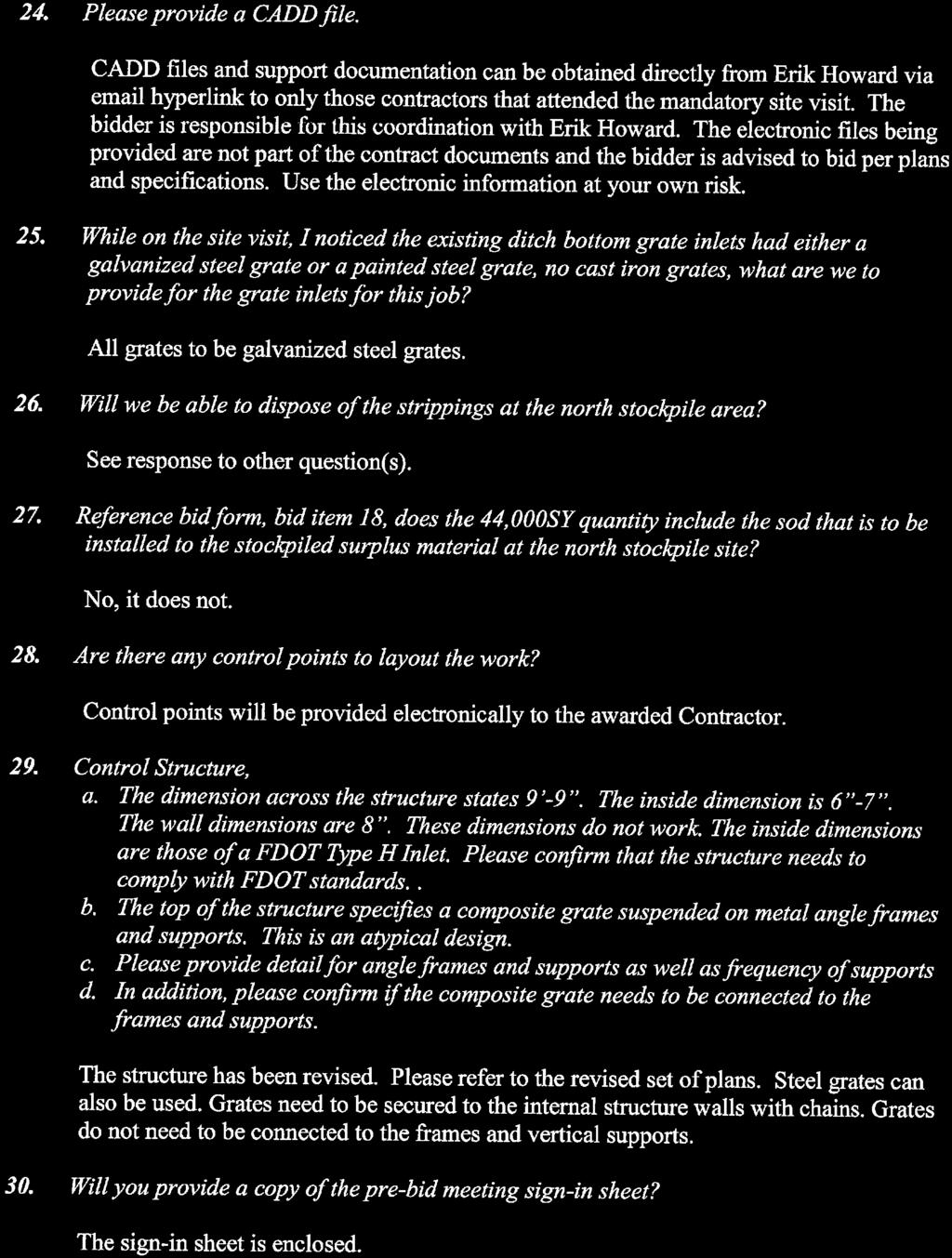
10 Section BID FORM PROJECT IDENTIFICATION: Stormwater Management System Improvements (Phase 1) Project SITE IDENTIFICATION: Peace River Water Supply Facility 8998 SW County Road 769 Arcadia, Florida THIS BID IS SUBMITTED TO: Peace River Manasota Regional Water Supply Authority 9415 Town Center Parkway Lakewood Ranch, Florida The undersigned Bidder proposes and agrees, if this Bid is accepted, to enter into an agreement with Owner in the form included in the Bidding Documents to perform all Work as specified or indicated in the Bidding Documents for the prices and within the times indicated in this Bid and in accordance with the other terms and conditions of the Bidding Documents Bidder accepts all of the terms and conditions of the Invitation to Bid and the Instructions to Bidders, including without limitation those dealing with the disposition of Bid security. This Bid will remain subject to acceptance for ninety (90) days after the day of Bid opening, or for such longer period of time that Bidder may agree to in writing upon request of Owner. Bidder will sign and submit the Agreement with the bonds and other documents required by the Bidding Documents to Owner within fifteen (15) days after the date of Owner's Notice of Award In submitting this Bid, Bidder represents that: A. Bidder has examined and carefully studied the Bidding Documents, the other related data identified in the Bidding Documents and the following Addenda, receipt of which is hereby acknowledged. No. Dated Peace River Manasota Regional Bid Form Water Supply Authority -1- November STORMWATER MANAGEMENT SYSTEM IMPROVEMENTS (PHASE 1) PROJECT
11 No. No. No. No. Dated Dated Dated Dated B. Bidder has visited the Site and become familiar with and is satisfied as to the general, local, and Site conditions that may affect cost, progress, and performance of the Work. C. Bidder is familiar with and is satisfied as to all Federal, state, and local laws and regulations that may affect cost, progress, and performance of the Work. D. Bidder has carefully studied all reports of explorations and tests of subsurface conditions at or contiguous to the Site, and all drawings of physical conditions in or relating to existing surface or subsurface structures at or contiguous to the Site. E. Bidder has obtained and carefully studied (or assumes responsibility for having done so) all additional or supplementary examinations, investigations, explorations, tests, studies, and data concerning conditions (surface, subsurface, and Underground Facilities) at or contiguous to the Site which may affect cost, progress, or performance of the Work or which relate to any aspect of the means, methods, techniques, sequences, and procedures of construction to be employed by Bidder, including applying the specific means, methods, techniques, sequences, and procedures of construction required by the Bidding Documents to be employed by Bidder, and safety precautions and programs incident thereto. F. Bidder does not consider that any further examinations, investigations, explorations, tests, studies, or data are necessary for the determination of this Bid or performance of the Work at the price(s) bid and within the time and in accordance with the other terms and conditions of the Bidding Documents. G. Bidder is aware of the general nature of work to be performed by Owner and others at the Site that relates to the Work indicated in the Bidding Documents. H. Bidder has correlated the information known to Bidder, information and observations obtained from visits to the Site, reports and drawings identified in the Bidding Documents, and all additional examinations, Peace River Manasota Regional Bid Form Water Supply Authority -2- November STORMWATER MANAGEMENT SYSTEM IMPROVEMENTS (PHASE 1) PROJECT
12 investigations, explorations, tests, studies, and data with the Bidding Documents. I. Bidder has given written notice to the Owner s Engineer of all conflicts, errors, ambiguities, or discrepancies that Bidder has discovered in the Bidding Documents, and the written resolution thereof is acceptable to Bidder. J. The Bidding Documents are generally sufficient to indicate and convey understanding of all terms and conditions for the performance of the Work for which this Bid is submitted Bidder further represents that this Bid is genuine and is not made in the Interest of or on behalf of any undisclosed individual or entity and is not submitted in conformity with any agreement or rules of any group, association, organization, or corporation. Bidder has not directly or indirectly induced or solicited any other Bidder to submit a false or sham Bid; Bidder has not solicited or induced any individual or entity to refrain from bidding; and Bidder has not engaged in corrupt, fraudulent, collusive, or coercive practices in competing for the Contract. For the purposes of this Paragraph 4.01: "corrupt practice" means the offering, giving, receiving, or soliciting of anything of value likely to influence the action of a public official in the bidding process; "fraudulent practice" means an intentional misrepresentation of facts made (a) to influence the bidding process to the detriment of Owner, (b) to establish bid prices at artificial non-competitive levels, or (c) to deprive Owner of the benefits of free and open competition; "collusive practice" means a scheme or arrangement between two or more Bidders, with or without the knowledge of Owner, a purpose of which is to establish bid prices at artificial, non-competitive levels; and "coercive practice" means harming or threatening to harm, directly or indirectly, persons or their property to influence their participation in the bidding process or affect the execution of the Contract Bidder has attended the mandatory pre-bid conference. Peace River Manasota Regional Bid Form Water Supply Authority -3- November STORMWATER MANAGEMENT SYSTEM IMPROVEMENTS (PHASE 1) PROJECT
13 5.01. Bidder will complete the Work for the following prices: Bidder proposes to complete the work for the following prices: BID Estimated Description Unit ITEM Quantity Unit Price Bid Price 1 Mobilization LS 1 $ $ 2 Clearing and Grubbing LS 1 $ $ 3 Silt Fence Installation LF 2,800 $ $ 4 Regular Excavation CY 40,000 $ $ 5 Fill and Grading CY 40,000 $ $ 6 18 RCP LF 600 $ $ 7 24 RCP LF 60 $ $ 8 18 MES EA 3 $ $ 9 24 MES EA 1 $ $ 10 Type C Inlet EA 6 $ $ 11 Type D Inlet EA 1 $ $ 12 Junction Box EA 1 $ $ 13 Structure CS-A EA 1 $ $ 14 Modify Existing Inlet EA 1 $ $ 15 Fencing LS 1 $ $ 16 Stabilization, Type B (12 thick) SY 20 $ $ 17 Optional Base Group 06 (8 thick) SY 20 $ $ 18 Superpave, Asphalt Concrete, SP , (repair) SY 20 $ $ 19 Rip-rap rubble (ditch lining with filter fabric) TN 360 $ $ 20 Performance Turf (sod, Bahia) SY 44,000 $ $ 21 Demolition LS 1 $ $ 22 Restoration LS 1 $ $ SUB TOTAL Bid Items 1 through $ 23 Owner s Allowance $50,000 TOTAL SUBTOTAL + Owner s BID Allowance PRICE $ The unit prices listed in Bid Items 1 through 3, Bid Items 6 through 14 and Bid Items 16 through 20 will be the basis of compensation for the actual quantities of Work performed as documented in the Contractor s pay applications and confirmed by Owner or Owner s Engineer. Compensation for Work completed under the Owner s Allowance will be as mutually agreed by formal Work Change Directive and/or Change Order. The basis of award will be the Contractor s TOTAL BID PRICE Bidder agrees that the Work will be Substantially Complete by one hundred eighty (180) consecutive calendar days following the Notice to Proceed and Peace River Manasota Regional Bid Form Water Supply Authority -4- November STORMWATER MANAGEMENT SYSTEM IMPROVEMENTS (PHASE 1) PROJECT
14 reach Final Completion within two hundred ten (210) consecutive calendar days following Owner issuance of Notice to Proceed. Substantially Complete is defined as all earth moving operations are complete. Final Completion is defined as total completion of all work including all punch list items Bidder accepts the provisions of the Agreement as to liquidated damages in the event of failure to complete the Work within the times specified above Communications concerning this Bid shall be sent to Bidder at the following address: SIGNATURE OF BIDDER Contractor's License Number License Expiration Date If an Individual By (signature of individual) doing business as Business address Phone No. Date If a Partnership By (firm name) Peace River Manasota Regional Bid Form Water Supply Authority -5- November STORMWATER MANAGEMENT SYSTEM IMPROVEMENTS (PHASE 1) PROJECT
15 (signature of general partner) Business address Phone No. Date If a Corporation By By (corporation name) (signature of authorized person) (Name/Title) Business address Phone No. Date If a Joint Venture (Other party must sign below.) Contractor's License Number License Expiration Date If an Individual By (signature of individual) doing business as Business address Phone No. Peace River Manasota Regional Bid Form Water Supply Authority -6- November STORMWATER MANAGEMENT SYSTEM IMPROVEMENTS (PHASE 1) PROJECT
16 Date If a Partnership By (firm name) (signature of general partner) Business address Phone No. Date If a Corporation By By (corporation name) (signature of authorized person) (Name/Title) Business address Phone No. Date End of Section Peace River Manasota Regional Bid Form Water Supply Authority -7- November STORMWATER MANAGEMENT SYSTEM IMPROVEMENTS (PHASE 1) PROJECT
17 Section MEASUREMENT AND PAYMENT 1. SCOPE. This section covers methods of measurement and payment for items of Work under this Contract. 2. GENERAL. The Total Bid Price shall cover all Work required by the Contract Documents. All costs in connection with the proper and successful completion of the Work, including furnishing all materials, equipment, supplies, and appurtenances; providing all construction equipment, and tools; and performing all necessary labor and supervision to fully complete the Work, shall be included in the lump sum and adjustment unit prices bid. All Work not specifically set forth as a pay item in the Bid Form shall be considered a subsidiary obligation of Contractor and all costs in connection therewith shall be included in the prices bid. 3. ESTIMATED QUANTITIES. All estimated quantities stipulated in the Bid Form or other Contract Documents are approximate and are to be used only as a basis for estimating the probable cost of the Work and for the purpose of comparing the Bids submitted for the Work. The actual amounts of work done and materials furnished under Unit Price items may differ from the estimated quantities. The Unit Price shall be the basis of payment for the actual amount of work done and materials furnished. Contractor agrees that it will make no claim for damages, anticipated profits, or otherwise on account of any difference between the amounts of work actually performed and materials actually furnished and the estimated quantities. 4. UNIT PRICES. The Bid Form requires unit prices for certain items of the Work. The quantities indicated for the unit price items are estimated. Payment shall be made for the items listed on the Bid Schedule on the basis of the Work performed and completed, such work including but not limited to, the furnishing of all necessary labor, materials, equipment, transportation, clean up, restoration of disturbed areas, and all other appurtenances to complete the construction and installation of the work as shown on the drawings and described in FDOT Standard Specifications for Road and Bridge Construction (July 2017). Some FDOT Standard Specifications for Road and Bridge Construction (July 2017) are included as a part of the contract documents. However, others not provided within the contract documents are included as part of the project. The following specifications supplement the 2017 edition of the FDOT Standard Specifications for Road and Bridge Construction. BID ITEM 5 Fill and Grading Fill material will be obtained from the onsite lake excavation and regrading. The Contractor shall sufficiently dewater excavated materials for use as backfill. Prior to filling, the ground surface shall be prepared by removing vegetation, debris, unsatisfactory soil materials (muck), obstructions, and deleterious materials. Fill shall be Peace River Manasota Regional Measurement and Payment Water Supply Authority -1- November STORMWATER MANAGEMENT SYSTEM IMPROVEMENTS (PHASE 1) PROJECT
18 brought up in substantially level lifts not exceeding 6 in depth. All fill materials shall be placed and compacted "in-the-dry. Compact each layer to required percentage of maximum dry density or relative dry density for each classification. Obtain a minimum density at any location of 98% of the Modified Proctor maximum density as determined by FM 1-T 180, Method D. At the time of compaction, the fill material should be at optimum moisture content, plus or minus 2 percent. The Contractor is responsible for all Geotechnical Testing, Quality Control and Quality Assurance. A Florida Licensed Engineer shall approve the subgrades and fill layers by certifying the structural integrity of the fill, as required for a building foundation. This unit cost work includes the cost for the Contractor to haul surplus excavated suitable fill material to the alternate stockpile site near reservoir No. 2 as shown on Sheet C-08 of the drawings. This unit cost work includes the cost for the Contractor to haul surplus excavated unsuitable fill material to the alternate stockpile site near reservoir No. 2 as shown on Sheet C-08 of the drawings and keep segregated from suitable material. BID ITEM 21 Demolition Demolition shall be paid on a lump sum basis and shall be full compensation for removal or disposal of materials as shown on plans and includes those items not specifically shown on the plans but normally required to be disposed of. BID ITEM 22 Restoration Restoration shall be paid on a lump sum basis and shall be full compensation for restoration or relocation or installation of all items shown on the plans and not specifically included in other payment items. This item includes full restoration of items damaged by the Contractor in the performance of the work. BID ITEM 23 - Owner s Allowance Owner s Allowance shall be utilized only with prior written consent of the Owner and only for work not specified within the Contract Documents. 5. SCHEDULE OF VALUES. Contractor shall provide a schedule of values to facilitate measurement and payment based on the actual progress of the Work after Award of Contract. Peace River Manasota Regional Measurement and Payment Water Supply Authority -2- November STORMWATER MANAGEMENT SYSTEM IMPROVEMENTS (PHASE 1) PROJECT
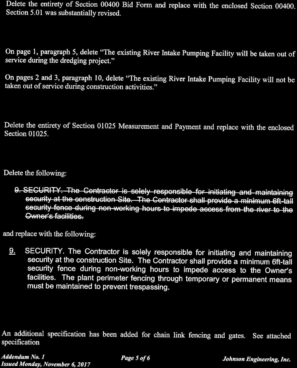
19 TECHNICAL SPECIFICATIONS AND CONDITIONS CHAIN LINK FENCING AND GATES PART 1 -- DESCRIPTION: This specification is for providing and installing Chain Link Fencing, Chain Link Fence Gates, removal of existing fencing systems, clearing along new Chain Link Fencing alignment paths and providing minimum 12-foot wide fire lanes where needed along each side of the new 8-foot chain link fence alignment; and sodding of disturbed areas along the new fence line. Existing fencing to be demolished shall be turned over to the Owner or disposed of at Owner s direction. 1.1 SECTION INCLUDES A. The Contractor shall provide chain link fencing for construction of fence lines at structures, manual gates, and appurtenant Work as shown on the drawings, complete, in accordance with the Contract Documents. B. Single Manufacturer: Chain link fencing, gates, accessories, fittings, and fastenings shall be products of a single manufacturer. 1.2 CONTRACTOR SUBMITTALS A. General: Furnish three copies of material shop drawings. B. Shop Drawings, shall include manufacturer s technical data, product specifications, standard details, certified product test results. PART 2 -- PRODUCTS 2.1 GENERAL A. Dimensions indicated herein for roll formed pipe are outside dimensions, excluding coatings. B. Fence fabric height shall be 8 feet unless otherwise indicated. C. Fencing materials shall be hot-dip galvanized after fabrication. CHAIN LINK FENCING AND GATES PAGE 1
20 D. Fencing shall be topped with 3 lines of barbed wire on single, 45 degree supporting arms, sloped outward. 2.2 STEEL FABRIC A. Fence fabric shall be No. 9 gauge steel wire, 2 inch mesh, with top selvages knuckled and bottom selvages twisted and barbed. B. Fabric Finish: Fabric shall be galvanized in conformance with ASTM A Zinc- Coated Steel Chain Link Fence Fabric, Class ll, with not less than 2.0 ounces zinc per square foot of coated surface. 2.3 FRAMING AND ACCESSORIES A. Steel Framework, General: Unless otherwise indicated, framework components shall be fabricated of galvanized steel conforming to ASTM A 53 - Pipe, Steel, Black and Hot- Dipped, Zinc-Coated Welded and Seamless, or ASTM A Zinc (Hot-Dip Galvanized) Coatings on Iron and Steel Products, with not less than 1.8 ounces zinc per square feet of coated surface. 1. Fittings and accessories shall be galvanized in accordance with ASTM A 153 Zinc Coating (Hot-Dip) on Iron and Steel Hardware, with zinc weights per Table I of that standard, except that no coating shall be less than 1.8-ounce zinc per square foot of coated surface. B. End, Corner and Pull Posts: Posts shall be one piece without circumferential welds, 3- inch schedule 40 pipe, 5.79 pounds per linear foot. C. Line Posts: Line posts shall be spaced no more than 10-feet on center and shall be schedule 40, 2-1/2 inch pipe, 3.65-pounds per linear foot. D. Gate Posts: Gate posts shall be 4-inch schedule 40 pipe, 9.1-pounds per linear foot. E. Top Rail: Top railing shall be provided in manufacturer s longest lengths, with expansion type couplings, approximately 6-inches long, for each joint. Fence design shall provide positive, secure attachment of top rail to each gate post, corner post, pull post and end post. Top rail and braces shall be 1-5/8 inch schedule 20 pipe, 2.27-pounds per linear foot. F. Tension Wire: Tension wire shall be located at the bottom of the fabric and shall consist of No. 7 gauge coated coil spring wire of metal and finish to match fabric. Tension wire CHAIN LINK FENCING AND GATES PAGE 2
21 shall be attached to the fabric along the extreme bottom of the fence. Tension wire attachment shall be with fabric tie wires at a spacing of no more than 24 inches apart. G. Fabric Tie Wires: Fabric tie wires shall be No. 9 gauge galvanized steel wire of the same finish as the fabric. Aluminum ties shall not be used. Ties shall be spaced 14 inches apart on posts and 24 inches apart on rails. H. Post Brace Assembly: Post brace assembly shall be manufacturer s standard adjustable brace assembly provided at each end post, gate post and at both sides of each corner post and intermediate brace post. Material used for brace shall be same as top rail. Truss bracing between line posts shall be achieved with inch diameter rod and adjustable tensioner. I. Post Tops: Post tops shall be weather-tight closure caps, designed for containment of top rail and positive permanent attachment to post. One cap shall be provided for each post. J. Stretcher Bars: Stretcher bars shall be one-piece lengths equal to the full height of the fabric, with minimum cross-section of 3/16-inch by 3-1/2 inch. One stretcher bar shall be provided for each gate and end post, and 2 for each corner and intermediate brace post. K. Stretcher Bar Bands: Stretcher bar bands shall be one-piece fabrications designed to secure stretcher bars to end, corner, intermediate brace, and gate posts. Bands shall have a minimum cross-section of 1/8-inch by 3/4-inch. Stretcher bar bands shall be spaced no more than 15-inches on center. L. Barbed Wire Supporting Arms: Supporting arms shall be manufacturer s standard fabrication, of metal and finish to match fence framework, with provision for anchorage to each post and attachment of three rows of barbed wire to each arm. Supporting arms may be either attached to posts or integral with post top weather cap. Supporting arm shall be single 45-degree arm type and shall be capable of withstanding 250 pounds of downward pull at outermost end. M. Barbed Wire: Barbed wire shall be 2 strand, No. 12-1/2 gauge zinc-coated steel or iron wire with four-point, 14-gauge barbs spaced no more than 5-inches apart. 2.4 GATES A. Fabrication: Perimeter frames of gates shall be fabricated from same metal and finish as fence framework. Gate frames shall be assembled by welding or with fittings and rivets CHAIN LINK FENCING AND GATES PAGE 3
22 for rigid, secure connections. Welds shall be ground smooth. Gate frames and any ungalvanized hardware, shall be hot-dip galvanized after fabrication. Horizontal and vertical members shall be provided to ensure proper gate operation and attachment of fabric, hardware and shall be hot-dip galvanized after fabrication. 1. Fabric for gates shall match fence fabric, unless otherwise indicated. Fabric shall be installed with stretcher bars at all perimeter edges. Stretcher bars shall be attached to gate frame with stretcher bar bands spaced no more than 15 inches on center. 2. Each gate shall be diagonally cross-braced with a 3/8-inch diameter adjustable length truss rod to ensure frame rigidity without sag or twist. 3. Where barbed wire is indicated above gates, vertical members shall be extended and fabricated as required to receive barbed wire supporting arms. B. Swing Gates: Perimeter frames of swing gates shall be constructed of Schedule 40 pipe and shall be fabricated by welding. Welds shall be ground smooth prior to hot-dip galvanizing. 1. Hardware and accessories shall be provided for each gate, galvanized in conformance with ASTM A 153, and in accordance with the following: 2.5 RELATED ITEMS a. Hinges: Hinges shall be of size and material to suit gate size, non-lift-off type, offset to permit 180-degree gate opening. Three hinges shall be provided for each leaf 6-feet or more in height. Latch: Latch shall be forked type or plunger- bar type, permitting operation from either side of the gate, with padlock eye as an integral part of the latch. b. Keeper: Keeper shall be provided which automatically engages the gate leaf and holds it in the open position until it is manually released. c. Double Gates: Gate stops shall be provided for double gates, consisting of mushroom type flush plate with anchors, set in concrete, and designed to engage center drop rod or plunger bar. Locking device and padlock eyes shall be provided as an integral part of the latch, permitting both gate leaves to be locked with a single padlock. A. Concrete: Concrete shall be 3000psi mix design or greater. CHAIN LINK FENCING AND GATES PAGE 4
23 B. Nuts, bolts and screws shall be steel, minimum size 3/8-inch diameter, hot-dip galvanized after fabrication. 2.6 MANUFACTURERS A. Manufacturer s Qualifications: Chain link fencing and gates shall be products of a single manufacturer which has been successfully engaged in the production of such items for a period of at least 5 years. B. InstaIIer s Qualifications: Installation of the chain link fence shall be by the manufacturer or by a firm accepted and licensed by the manufacturer. C. Manufacturers, or equal 1. American Fence Corp. 2. Anchor Fence, Inc. 3. United States Steel PART 3 -- EXECUTION 3.1 INSPECTION A. Prior to commencing installation, require Installer to inspect all areas and conditions within which Work of this Section will be performed. Dimensions and clearances shall be verified. Final grading shall be completed and all earth, brush, or other obstructions which interfere with the proper alignment and construction of fencing shall be removed. B. Inspection Utility Location Do not dig until all nearby utilities have been located. In some areas it may be necessary to hand dig post holes. If the Contractor disrupts or breaks any utility line as a result of digging in areas not approved or through carelessness, repair costs shall be the sole responsibility of the Contractor. C. Electrical Grounds Wherever an Overhead Power Line crosses over a fence or runs parallel within 20 feet of Overhead Power Lines, install a ground directly below the point of crossing or every 200 LF as applicable. Install a ground rod consisting of a galvanized rod with connection of similar metal 10 feet in length and at least 5/8 inches in diameter. Drive the rod until the top of the rod is 6-inches below grade. Use a No. 6 conductor to connect the rod to all fence elements. Connect the conductor to each fence element and ground rod by means of electrical-type clamps which will prevent corrosion. 3.2 INSTALLATION CHAIN LINK FENCING AND GATES PAGE 5
24 A. General: Unless otherwise indicated, all posts shall be set in concrete. Gate and related posts, corner posts, and other critical elements shall be provided with concrete foundations which are designed by an engineer to safely accommodate the loads to which they will be subjected. B. Excavation: Holes for posts shall be drilled or hand excavated to the diameters and spacing indicated, in firm, undisturbed or compacted soil. Post foundations which are not designed by an engineer shall comply with the following: 1. Holes shall be excavated to a diameter not less than 12 inches or not less than 5 times the largest dimension of the item being anchored, whichever is larger. 2. Depth for holes shall be not less than 40 inches; excavated approximately 4 inches lower than the post bottom, with bottom of posts set not less than 36 inches below finish grade surface. C. Setting Posts: Line posts shall be spaced at not more than 10-foot intervals, measured from center to center of the posts, parallel to the ground slope. Posts shall be set plumb and shall be centered in holes, 4 inches above the bottom of the excavation, with posts extending not less than 36 inches below finish grade surface. 1. Corner posts shall be installed where changes in the fence lines equal or exceed 15 degrees, measured horizontally. 2. Each post shall be properly aligned vertically and its top aligned parallel to the ground slope. Posts shall be maintained in proper position during placement and finishing operations. D. Concrete: 1. Concrete for footings may be placed without forms, providing the ground is firm enough to permit excavation to neat line dimensions. Prior to placing concrete, the earth around the hole shall be thoroughly moistened. 2. Encasement concrete for footings shall be placed immediately after mixing in a manner such that there will be no concentration of the large aggregates. The concrete shall be consolidated by tamping or vibrating. 3. Concrete footings shall have a neat appearance and shall be extended 2 inches above grade and troweled to a crown to shed water. CHAIN LINK FENCING AND GATES PAGE 6
25 4. A minimum of 7 days shall elapse after placing the concrete footings before the fence fabric or barbed wire is fastened to the posts. E. Bracing: Bracing shall be provided at all ends, corners, gates, and intermediate brace posts. Corner posts and intermediate brace posts shall be braced in both directions. Horizontal brace rails shall be set midway between the top rail and the ground, running from the corner, end, intermediate brace or gate post to the first line post. Diagonal tension members shall connect tautly between posts below horizontal braces. 1. Braces shall be so installed that posts remain plumb when diagonal rod is under proper tension. F. Intermediate Brace Posts: Where straight runs of fencing exceed 500 feet, intermediate brace posts shall be installed, spaced equally between ends or corners; with additional posts provided as required, such that the spacing between intermediate brace posts does not exceed 500 feet. Intermediate brace posts shall be equivalent in size to corner posts and shall be braced with horizontal brace rails and diagonal tension members in both directions. G. Top Rails: Top rails shall be run continuously through post caps, bending to radius for curved runs. Expansion couplings shall be provided as recommended by the fencing manufacturer. H. Tension Wire: Continuous bottom tension wire shall be stretched tight with turnbuckles at end, gate, intermediate, and corner posts. Tension wire shall be installed on a straight grade between posts, with approximately 2 inches of space between finish grade and bottom selvage, unless otherwise indicated. Tension wire shall be tied to each post with not less than 6 gauge galvanized wire. I. Fabric: 1. Chain Link fabric shall be fastened on the secured side of the posts. 2. Fabric shall be stretched and securely fastened to posts. Between posts, top and bottom edges of the fabric shall be fastened to the top rail and bottom tension wire, respectively. 3. Fabric shall be stretched and anchored in such a manner that it remains in tension after the pulling force is released. CHAIN LINK FENCING AND GATES PAGE 7
26 J. Tie Wires: Tie wire shall be bent to conform to the diameter of the pipe to which it is attached, clasping pipe and fabric firmly with ends twisted at least two full turns. Ends of wire shall be bent back to minimize hazard to persons or clothing. 1. Fabric shall be tied to line posts with tie wires spaced at 12 inches on center. 2. Fabric shall be tied to rails and braces with tie wires spaced at 24 inches on center. 3. Fabric shall be tied to tension wires, with hog rings spaced 24 inches on center. K. Stretcher Bars: Fabric shall be fastened to end, corner, intermediate brace, and gate posts with stretcher bars. Bars shall be threaded through or clamped to fabric at 4 inches on center and secured to posts with stretcher bar bands spaced no more than 14 inches on center. L. Fasteners: Nuts for tension bands and hardware bolts shall be installed on the side of fence opposite the fabric side. Ends of bolts shall be peened or the threads scored to prevent removal of nuts. M. Galvanized coating damaged during construction of the fencing shall be repaired by application of Galvo-Weld; Galvinox; or equal. CHAIN LINK FENCING AND GATES PAGE 8
27 CHAIN LINK FENCE STANDARD DETAILS CHAIN LINK FENCING AND GATES PAGE 9

28 CHAIN LINK FENCE STANDARD DETAILS - END OF SECTION - CHAIN LINK FENCING AND GATES PAGE 10


29 CONSTRUCTION PLANS FOR PEACE RIVER MANASOTA REGIONAL WATER SUPPLY AUTHORITY PEACE RIVER FACILITY CONCEPTUAL STORMWATER PLAN & PHASE 1 IMPROVEMENTS SECTIONS 10, 15 AND 16 TOWNSHIP 39 S., RANGE 23 E. DESOTO COUNTY, FLORIDA 27 05' 27.44" Latitude ' 10.29" Longitude Peace River Manasota Regional Water Supply Authority Board of Directors: PROJECT LOCATION Alan Maio, Chair Sarasota County Commissioner Elton A. Langford, Vice Chair DeSoto County Commissioner Betsy Benac Manatee County Commissioner Ken Doherty Charlotte County Commissioner Prepared By: Prepared For: LOCATION MAP OCTOBER 2017 Bid Set SHEET NUMBER C-01
30 ABBREVIATIONS SYMBOLS GENERAL NOTES: PAVING, GRADING AND DRAINAGE NOTES: JOHNSON ENGINEERING, INC JOHNSON STREET P.O. BOX 1550 FORT MYERS, FLORIDA PHONE: (239) FAX: (239) E.B. #642 & L.B. #642 MH-1 HATCH PATTERNS SIGNING AND PAVEMENT MARKING NOTES: SITE DEMOLITION: EXISTING FM SS WM IRR LINETYPES NOTE: HATCH PATTERNS ARE FOR ILLUSTRATIVE PURPOSES ONLY, ACTUAL HATCH PATTERNS ON DRAWING MAY VARY IN SCALE & ANGLE PROPOSED FM SS WM IRR EXISTING UTILITY NOTE: Peace River Facility Conceptual Stormwater Plan & Phase 1 Improvements RU RU X X X X X X HORIZONTAL SEPARATION OF PIPELINES SEPARATION OF WATER AND SEWER LINES ALTERNATE CONSTRUCTION REVISIONS NO. DESCRIPTION DATE DATE: OCTOBER 2017 VERTICAL SEPARATION OF PIPELINES PROJECT NO FILE NO SCALE: AS SHOWN General Notes, Legend and Abbreviations Bid Set SHEET NUMBER C-02
 LEGEND PROPERTY BOUNDARY PHASE 1 CONSTRUCTION LIMITS FLOODPLAIN LIMITS EXISTING DIRECTION OF FLOW EXISTING WETLANDS SURFACE WATERS y 76 The aerial photograph")

31 ERIK LEE HOWARD, PE FL License No JOHNSON ENGINEERING, INC JOHNSON STREET P.O. BOX 1550 FORT MYERS, FLORIDA PHONE: (239) FAX: (239) E.B. #642 & L.B. #642 (INTENDED DISPLAY SCALE: 1"=200') LEGEND PROPERTY BOUNDARY PHASE 1 CONSTRUCTION LIMITS FLOODPLAIN LIMITS EXISTING DIRECTION OF FLOW EXISTING WETLANDS SURFACE WATERS y 76 The aerial photograph shown were provided by FDOT and were taken in Peace River Facility Conceptual Stormwater Plan & Phase 1 Improvements CR 1 DESCRIPTION DATE Wetland lines flagged by Johnson Engineering, Inc. and survey located by Banks Engineering. REVISIONS CR NOTES: Hw NO 's ing -K DATE: Intake Structure OCTOBER 2017 PROJECT NO FILE NO. SCALE: AS SHOWN Project Boundary Ac Aerial & Existing Drainage Map Bid Set SHEET NUMBER C-03
 334-0046 FAX: (239) 334-3661 E.B.")
32 JOHNSON ENGINEERING, INC JOHNSON STREET P.O. BOX 1550 FORT MYERS, FLORIDA PHONE: (239) FAX: (239) E.B. #642 & L.B. #642 S4 S4 LEGEND PROPERTY BOUNDARY PHASE 1 CONSTRUCTION LIMITS FLOODPLAIN LIMITS P2 X X X X X X X EXISTING WETLANDS PROPOSED STORMWATER POND SURFACE WATER IMPACT (1.13 ACRES) S1 S1 EXISTING SLUDGE DRYING BED TO REMAIN S2 S3 S6 S5 S6 S6 P1 S5 S6 P1 P6A POND A 2.1 AC. CONTROL EL = 11.0 P6B P6B X X X X X X XX X P5 P4 P4 P2 P3 X X X X P3 NOTE: PROPOSED BUILDINGS PROPOSED IMPERVIOUS Clear and Grub inside Construction Limits The aerial photographs shown were provided by FDOT and were taken in See Sheet C-06 for Typical Sections. REVISIONS NO. DESCRIPTION DATE DATE: Peace River Facility Conceptual Stormwater Plan & Phase 1 Improvements OCTOBER 2017 X PROJECT NO FILE NO S2 P6A SCALE: AS SHOWN S3 P5 Contruction Phase Site Plan Bid Set SHEET NUMBER C-04

33 BASIN A 29.6 AC EXISTING SLUDGE DRYING BED TO REMAIN 1.8 AC X X X X X X X X X X X X X X X X X X X X X X X X X X X X X X X X X X X X X X X X X X X X X POND A 2.1 AC. CONTROL EL = 11.0 NOTE: Excess Excavation to be hauled to Spoil Stockpile North of Kings Highway. See Sheet C-08 for Locations. X X X X LEGEND NOTES: PROPERTY BOUNDARY PHASE 1 CONSTRUCTION LIMITS BASIN LIMITS EXISTING WETLANDS PROPOSED STORMWATER PONDS EXISTING DIRECTION OF FLOW PROPOSED DIRECTION OF FLOW EXISTING POND TO BE FILLED PROPOSED ASPHALT REPAIR EXISTING ELEVATION PROPOSED ELEVATION PROPOSED CONTOUR Suitable material from excavation to be placed in proposed fill areas. Excess material to be stored in stockpiles shown on sheet C-08. The aerial photograph shown were provided by FDOT and were taken in Wetland lines flagged by Johnson Engineering, Inc. and survey located by Banks Engineering. Existing Survey Topo shown from Banks Engineering, Inc dated 3/17/2017 and JH McCarrier Land Surveying, Inc dated 2/7/2017. Contour lines derived from RAW LAS files from SWFWMD and reference the National Geodetic Vertical Datum of 1929 (NGVD 29), dated JOHNSON ENGINEERING, INC JOHNSON STREET P.O. BOX 1550 FORT MYERS, FLORIDA PHONE: (239) FAX: (239) E.B. #642 & L.B. #642 REVISIONS NO. DESCRIPTION DATE DATE: PROJECT NO FILE NO. SCALE: Peace River Facility Conceptual Stormwater Plan & Phase 1 Improvements OCTOBER 2017 Grading & Fill Plan Bid Set SHEET NUMBER C AS SHOWN
34 JOHNSON ENGINEERING, INC JOHNSON STREET P.O. BOX 1550 FORT MYERS, FLORIDA PHONE: (239) FAX: (239) E.B. #642 & L.B. #642 P1 POND TYPICAL DETAIL S1 SWALE TYPICAL DETAIL S2 SLUDGE DRYING BED SWALE-BERM TYPICAL DETAIL P2 PROPERTY LINE - POND P3 POND - NATURAL GRADE TYPICAL DETAIL P4 POND LITTORAL ZONE TRANSITION TYPICAL DETAIL S3 TEMPORARY SPOIL SWALE TYPICAL DETAIL S4 SWALE - NATURAL GRADE TYPICAL DETAIL Peace River Facility Conceptual Stormwater Plan & Phase 1 Improvements P5 POND LITTORAL ZONE AND BERM TYPICAL DETAIL S5 SLUDGE DRYING BED - POND TYPICAL DETAIL REVISIONS NO. DESCRIPTION DATE DATE: OCTOBER 2017 PROJECT NO FILE NO SCALE: AS SHOWN Typical Sections P6A SPREADER SWALE TYPICAL DETAIL P6B SPREADER SWALE TYPICAL DETAIL S6 SWALE - INLET - POND TYPICAL DETAIL Bid Set SHEET NUMBER C-06

35 JOHNSON ENGINEERING, INC JOHNSON STREET P.O. BOX 1550 FORT MYERS, FLORIDA PHONE: (239) FAX: (239) E.B. #642 & L.B. #642 TYPICAL PAVEMENT SECTION Peace River Facility Conceptual Stormwater Plan & Phase 1 Improvements CONTROL STRUCTURES CS-A REVISIONS NO. DESCRIPTION DATE EXISTING UNDERDRAIN DATE: OCTOBER 2017 PROJECT NO FILE NO SCALE: AS SHOWN Control Section Details Bid Set SHEET NUMBER C-07


 DESCRIPTION 23 DATE 24 -K 24 CR 9 23 in 76 DATE: OCTOBER 2017 PROJECT NO. 20160040-005 10-23-39 FILE NO.")
36 ALTERNATE STOCKPILE LOCATION MAX HEIGHT 16' 4:1 SLOPES SODDED LEGEND JOHNSON ENGINEERING, INC JOHNSON STREET P.O. BOX 1550 FORT MYERS, FLORIDA PHONE: (239) FAX: (239) E.B. #642 & L.B. #642 PROPERTY BOUNDARY SILTFENCE EXISTING WETLANDS PROPOSED POND NOTES: 1. The aerial photograph shown were provided by FDOT and were taken in Wetland lines flagged by Johnson Engineering, Inc. and survey located by Banks Engineering. CR 7 61 PROJECT BOUNDARY Peace River Facility Conceptual Stormwater Plan & Phase 1 Improvements STOCKPILE LOCATION MAX HEIGHT 16' 4:1 SLOPES SODDED SOD ALL DISTURBED AREA wy H g's 22 SILT FENCE TO BE INSTALLED UPON EMPLACEMENT OF FILL AND TO REMAIN IN PLACE UPON PROJECT COMPLETION REVISIONS 22 SILT FENCE (TYPICAL) NO. SOIL TRACKING DEVICE (TYPICAL) DESCRIPTION 23 DATE 24 -K 24 CR 9 23 in 76 DATE: OCTOBER 2017 PROJECT NO FILE NO. SCALE: AS SHOWN Erosion Control Plan And Details Bid Set SHEET NUMBER C-08
SECTION CHAIN LINK FENCES
 SECTION 02 44 40 PART 1 - GENERAL 1.1 DESCRIPTION A. Work included: Provide chain link fence system where shown on the Drawings, as specified herein, and as needed for a complete and proper installation.
SECTION CHAIN LINK FENCES AND GATES (PARK)
") SECTION 02821 CHAIN LINK FENCES AND GATES (PARK) PART I GENERAL 1.1 SECTION INCLUDES A. Installation of chain link fences, and gate units provided by single source including erection accessories, fittings,
SECTION 02821 CHAIN LINK FENCES AND GATES (PARK) PART I GENERAL 1.1 SECTION INCLUDES A. Installation of chain link fences, and gate units provided by single source including erection accessories, fittings,
ITEM 555 CHAIN LINK FENCING
 ITEM 555 AFTER MARCH 1, 2012 CHAIN LINK FENCING 555.1 Description. This item shall govern for furnishing the quantities of chain link fencing and gates as shown on the plans, including all posts, bracing
CONSOLIDATED EDISON COMPANY OF NEW YORK, INC. 4 IRVING PLACE NEW YORK, NY DISTRIBUTION ENGINEERING DISTRIBUTION EQUIPMENT
 CONSOLIDATED EDISON COMPANY OF NEW YORK, INC. 4 IRVING PLACE NEW YORK, NY 10003 DISTRIBUTION ENGINEERING DISTRIBUTION EQUIPMENT SPECIFICATION EO-1124 REVISION 3 November 2013 EFFECTIVE DATE November 11,
CITY OF MOUNT DORA LIFT STATION CHAINLINK FENCE AND GATE SPECIFICATIONS
 CITY OF MOUNT DORA LIFT STATION CHAINLINK FENCE AND GATE SPECIFICATIONS PART 1 - GENERAL 1.01 SUMMARY A. Section Includes furnishing and installing chain-link fabric fence, gate, and appurtenances. 1.02
TITLE: CAMP JOHNSON OVERPASS / HWY 17 BYPASS SECURITY FENCE UPGRADES
 CONTRACT # N40085-15B-0457 PROJECT # 15R036CN MACC # 15-0457 MAXIMO# 4608934 TITLE: CAMP JOHNSON OVERPASS / HWY 17 BYPASS SECURITY FENCE UPGRADES ATTACHMENTS: 1. 15-0457 CJ OVERPASS SECURITY UPGRADES Site
CITY OF FRIENDSWOOD TECHNICAL SPECIFICATIONS DOCUMENT 00085B ADDENDUM ADDENDUM NO. 1
 ADDENDUM Date of Addendum: December 30 th, 2015 PROJECT NAME: Fencing for Sportspark PROJECT NO: GO1507 BID DATE: Tuesday, January 5 th, 2016 FROM: City of Friendswood Department of Public Works 1306 Deepwood
SECTION 1208 CHAIN LINK FENCING DESCRIPTION
 SECTION 1208 CHAIN LINK FENCING 1208-1 DESCRIPTION This item covers the requirements for furnishing materials and constructing new chain link fences and gates in accordance with the details included herein
SECTION CHAIN LINK FENCING
 SECTION 02835 - CHAIN LINK FENCING 1.0 GENERAL 1.1 Furnish and install chain link fencing complete in place with gates and accessories as specified herein and as shown on the Contract Drawings. 1.2 Reference
Colorado River Aqueduct Pumping Plants 230 kv Disconnect Switches Replacement
 DATE: July 15, 2011 ADDENDUM NUMBER: 2 MODIFYING: Specifications No. 1698 PROJECT: Colorado River Aqueduct Pumping Plants 230 kv Disconnect Switches Replacement BID TIME AND DATE: 2:00 p.m., July 19, 2011
SECTION CHAIN LINK FENCING
 Section 02444 1 SECTION 02444 CHAIN LINK FENCING PART 1 - GENERAL 1.01 DESCRIPTION A. Requirement. Under these specifications, the Contractor shall furnish all materials, labor, tools, and equipment required
SECTION CHAIN LINK FENCES AND GATES (GALVANIZED) A. Fence framework, fabric, gates, and accessories.
 A. Fence framework, fabric, gates, and accessories.") SECTION 02830 CHAIN LINK FENCES AND GATES (GALVANIZED) 1.0 GENERAL 1.1 Section Includes A. Fence framework, fabric, gates, and accessories. B. Excavation for post bases; concrete footing for posts. C.
SECTION 02830 CHAIN LINK FENCES AND GATES (GALVANIZED) 1.0 GENERAL 1.1 Section Includes A. Fence framework, fabric, gates, and accessories. B. Excavation for post bases; concrete footing for posts. C.
Houston Community College 3200 Main Parking Garage November 15, 2010 Houston Community College
 SECTION 323113 - CHAIN LINK FENCES AND GATES PART 1 - GENERAL 1.1 RELATED DOCUMENTS A. Drawings and general provisions of the Contract, including General and Supplementary Conditions and Division 01 Specification
SECTION 2831 ITEM F-162 CHAIN-LINK FENCES
 SECTION 2831 ITEM F-162 CHAIN-LINK FENCES PART 1 - GENERAL 1.1 DESCRIPTION. This item shall consist of furnishing and erecting a chain-link fence in accordance with these specifications and the details
00900 ADDENDUM #1. All Document Holders of Record. Date: February 16, Bayfield Waterline Replacement Project
 00900 ADDENDUM #1 Issued to: All Document Holders of Record Date: February 16, 2016 Project: Bayfield Waterline Replacement Project This Addendum forms a part of the Contract described above. The original
A NEW PRE-K BUILDING FOR BIG SPRING LAKE KINDERGARTEN SCHOOL FOR THE ALBERTVILLE CITY BOARD OF EDUCATION ALBERTVILLE, ALABAMA
 McKee and Associates Architecture and Interior Design Addendum No. FOUR Date: 09.24.18 Project: A NEW PRE-K BUILDING FOR BIG SPRING LAKE KINDERGARTEN SCHOOL FOR THE ALBERTVILLE CITY BOARD OF EDUCATION
SECTION BID FORM. Garfield Street Drainage Improvements
 SECTION 00410 BID FORM Garfield Street Drainage Improvements ARTICLE 1 - BID RECIPIENT 1.01 This Bid is submitted to: City of Lindsborg, Kansas City Clerk s Office 101 S. Main Street Lindsborg, KS 67456
CHAIN LINK FENCES AND GATES
 SECTION 02831 CHAIN LINK FENCES AND GATES PART 1 GENERAL 1.01 SUMMARY A. Alternate Material for Fence Post and Framing Material: Where schedule 40 galvanized steel is specified, the following will be accepted:
CHAIN LINK FENCES AND GATES
 SECTION 02831 CHAIN LINK FENCES AND GATES PART 1 GENERAL 1.01 REFERENCES AND CODES A. Florida Department of Education, Office of Educational Facilities - State Requirements for Educational Facilities -
SECTION CHAIN LINK FENCES AND GATES
 SECTION 02831 CHAIN LINK FENCES AND GATES PART 1 GENERAL 1.01 REFERENCES AND CODES A. Florida Department of Education, Office of Educational Facilities - State Requirements for Educational Facilities -
 extrudesection 00301 BID FORM PROJECT IDENTIFICATION: CONSTRUCTION OF PROPOSED DRAINAGE IMPROVEMENTS THIS BID IS SUBMITTED TO: THE CITY OF FREDERICKSBURG, TEXAS, herein after referred to as OWNER. 1. Enter
SECTION CHAIN-LINK FENCES AND GATES 02821/1
 SECTION 02821 - CHAIN-LINK FENCES AND GATES 02821/1 PART 1 - GENERAL 1.1 SUMMARY A. This Section includes the following: 1. Chain-Link Fences: 2. Gates: horizontal slide or swing. 3. Fences installed where
OCONEE COUNTY PROCUREMENT OFFICE 415 S. PINE STREET, ROOM 100 WALHALLA, SC Robyn M. Courtright, CPPO, Procurement Director
 OCONEE COUNTY PROCUREMENT OFFICE 415 S. PINE STREET, ROOM 100 WALHALLA, SC 29691 Robyn M. Courtright, CPPO, Procurement Director Tronda Spearman, CPPB, Assistant Procurement Director Telephone: 864-638-4141
SECTION CHAIN LINK FENCES AND GATES
 SECTION 32 31 13 CHAIN LINK FENCES AND GATES PART 1 GENERAL 1.1 SUMMARY A. This Section includes materials applicable for commercial/industrial and security vinyl coated chain link fence and framework.
SECTION BID FORM JACKSON AVENUE / 15TH STREET WATER MAIN REPLACEMENT
 ARTICLE 1 BID RECIPIENT 1.01 This Bid is submitted to: SECTION 00410 BID FORM JACKSON AVENUE / 15TH STREET WATER MAIN REPLACEMENT WESTERN VIRGINIA WATER AUTHORITY ATTN: Earl Smith Engineering Services
The purpose of this addendum is to respond to RFI s submitted to the County and issue a revised SECTION BID FORM.
 HIGHLANDS COUNTY BOARD OF COUNTY COMMISSIONERS (HCBCC) PURCHASING DEPARTMENT DATE: 6/19/15 BID NO. ITB 15-044 ADDENDUM No. 2 Project.: Owner: Lake Josephine Drive resurfacing Highlands County BCC Attn:
Special Provision No. 541S01 October OPSS 541, Construction Specifications for Chain Link Fence, is deleted and replaced with the following:
 CHAIN LINK FENCE - Item No. GATES - Item No. Special Provision No. 541S01 October 1998 AMENDMENT TO OPSS 541, DECEMBER 1990 OPSS 541, Construction Specifications for Chain Link Fence, is deleted and replaced
CONSTRUCTION SPECIFICATION FOR CHAIN LINK FENCE
 ONTARIO PROVINCIAL STANDARD SPECIFICATION METRIC OPSS 541 DECEMBER 1990 CONSTRUCTION SPECIFICATION FOR CHAIN LINK FENCE 541.01 SCOPE 541.02 REFERENCES 541.03 DEFINITIONS 541.05 MATERIALS TABLE OF CONTENTS
A. Product Data shall be provided for each type of product indicated.
 32 31 13 CHAIN LINK FENCES AND GATES SECTION 1 GENERAL 1.1 SUMMARY This Section includes the following: 1. Chain Link Fences 2. Gates for Chain Link Fences. See electrical specifications for electrical
SECTION BID FORM LICK RUN INTERCEPTOR REHABILITATION
 SECTION 00410 BID FORM LICK RUN INTERCEPTOR REHABILITATION ARTICLE 1 BID RECIPIENT 1.01 This Bid is submitted to: WESTERN VIRGINIA WATER AUTHORITY ATTN: Earl Smith, P.E. Engineering Services Third Floor,
CONSTRUCTION SPECIFICATION FOR CHAIN-LINK FENCE
 ONTARIO PROVINCIAL STANDARD SPECIFICATION METRIC OPSS 541 NOVEMBER 2005 CONSTRUCTION SPECIFICATION FOR CHAIN-LINK FENCE TABLE OF CONTENTS 541.01 SCOPE 541.02 REFERENCES 541.03 DEFINITIONS 541.04 SUBMISSION
MO: Tl RSA: 1406B
 MO: Tl425-02 SECTION 323113- CHAIN LINK FENCES AND GATES PART 1- GENERAL 1.1 RELATED DOCUMENTS Drawings and general provisions of the Contract, including General and Supplementary Conditions and Division
The Contract Documents for the referenced project are hereby amended in the following particulars only, with all other conditions remaining unchanged.
 1700 East Iron Ave. Salina, KS 67401 785-827-0433 phone 785-827-5949 fax 6 March 2018 Arizona California Colorado Kansas Louisiana Missouri Nebraska New Mexico Texas Utah ADDENDUM NO. 2 RE: City of Kingman,
SECTION NEW MARTINSVILLE FIREMAN S DOCK BIDS DUE: 4:30 PM LOCAL TIME ON FRIDAY JANUARY 30 TH, 2015
 SECTION 00 91 13.01 NEW MARTINSVILLE FIREMAN S DOCK ADDENDUM #2 ADDENDUM #2 ISSUE DATE: JANUARY 21, 2015 PROJECT NAME: NEW MARTINSVILLE FIREMAN S DOCK BIDS DUE: 4:30 PM LOCAL TIME ON FRIDAY JANUARY 30
Attached please find the revised Plan Sheet C3 Proposed Conditions Plan.
 ADDENDUM NO. 1 124002-4A RE: FROM: TO: Depot Street Drainage Improvements Charlestown, New Hampshire DuBois & King, Inc. P.O. Box 339 Randolph, Vermont 05060 (802) 728-3376 Prospective Bidders DATE: June
CONSTRUCTION SPECIFICATION FOR CHAIN-LINK FENCE
 ONTARIO PROVINCIAL STANDARD SPECIFICATION METRIC OPSS 772 NOVEMBER 2010 CONSTRUCTION SPECIFICATION FOR CHAIN-LINK FENCE TABLE OF CONTENTS 772.01 SCOPE 772.02 REFERENCES 772.03 DEFINITIONS 772.04 DESIGN
ADDENDUM NUMBER ONE (1) December 6, The following Addendum shall be incorporated into the Contract Documents for the above referenced project.
 December 6, The following Addendum shall be incorporated into the Contract Documents for the above referenced project.") TO: ALL HOLDERS OF CONTRACT DOCUMENTS FOR: City of Carlsbad, New Mexico Sanitary Sewer Interceptor 118 Upgrades Phase I Wade M. Chacon P.E. HDR Project Manager/Engineer Bid # 2016-32 ADDENDUM NUMBER ONE
TO: ALL HOLDERS OF CONTRACT DOCUMENTS FOR: City of Carlsbad, New Mexico Sanitary Sewer Interceptor 118 Upgrades Phase I Wade M. Chacon P.E. HDR Project Manager/Engineer Bid # 2016-32 ADDENDUM NUMBER ONE
CONSTRUCTION SPECIFICATION FOR CHAIN-LINK FENCE
 ONTARIO PROVINCIAL STANDARD SPECIFICATION OPSS.PROV 772 NOVEMBER 2017 (Formerly OPSS 772, November 2012) Note: The PROV published in November 2017 replaces OPSS 772 COMMON, November 2012 with no technical
SECTION 410 FENCES All materials shall be new and without flaws or defects of any type GENERAL
 SECTION 410 FENCES 410.1 GENERAL This work shall consist of the construction of fences and gates in substantial compliance with the specifications, lines, and grades shown on the plans or established by
CW 3550 Chain Link and Drift Control Fence TABLE OF CONTENTS
 January 2014 SPECIFICATION CW 3550 R3 CW 3550 Chain Link and Drift Control Fence TABLE OF CONTENTS 1. GENERAL CONDITIONS... 1 3. DESCRIPTION... 1 5. MATERIALS... 1 5.1 Drift Control Fence... 1 5.1.1 Approved
PROJECT MANUAL FENCING FOR PEPSI WATER TANK & ROCKTOWN WATER TANK FOR TOWN OF KINGSTREE KINGSTREE, SOUTH CAROLINA
 PROJECT MANUAL FENCING FOR PEPSI WATER TANK & ROCKTOWN WATER TANK FOR TOWN OF KINGSTREE KINGSTREE, SOUTH CAROLINA APRIL 2016 TABLE OF CONTENTS PROJECT MANUAL FENCING FOR PEPSI WATER TANK & ROCKTOWN WATER
Bear Exhibit Fence Upgrades. The following modifications are hereby made part of the contract documents:
 ADDENDUM TO BID T2017-04 Metropolitan Park District Department of Planning, Design and Development 4702 South 19 th Street Tacoma WA 98405 Date Prepared: November 17, 2017 Bid Number: T2017-04 Addendum
Answer 1: The reference to CB 5 is incorrect. The correct reference should be CB 4. Question 2: Have any potential staging areas been identified?
 ADDENDUM NO. 1 July 26, 2017 223837 RE: FROM: TO: CITY OF BARRE HMGP STORM DRAIN IMPROVEMENT PROJECTS DuBOIS & KING, INC. P.O. Box 339 Randolph, Vermont 05060 (802) 728-3376 Prospective Bidders This Addendum
SECTION FENCING. A. PART A and DIVISION 1 of PART B are hereby made a part of this SECTION.
 SECTION 323100 PART 1 GENERAL 1.01 GENERAL REQUIREMENTS A. PART A and DIVISION 1 of PART B are hereby made a part of this SECTION. B. Examine all conditions as they exist at the project prior to submitting
Advisory Circular PAGECONTROLCHART. Remove Pages Dated II Inscr t Pages Dated l/2/ thru 258-l 7/6/ l/2/90
 U.S. Department of Transportation Federal Aviation Administration Advisory Circular Subject: Change 8 to STANDARDS FOR SPECIFYING CONSTRUCTION OF AIRPORTS Date: 7/6/94 AC No: 150/53701OA Initiated by:
SECTION CHAIN LINK FENCES AND GATES
 SECTION 32 31 13 CHAIN LINK FENCES AND GATES SPEC WRITER NOTE: 1. Delete text between // // not applicable to project. Edit remaining text to suit project. 2. Use this section in specifying permanent chain
MERCHANTS METALS. A. ASTM F552 Standard Terminology Relating to Chain Link Fencing
 MERCHANTS METALS SECTION 32 31 13 COLORBOND CHAIN LINK FENCE AND GATES 2014 PART 1 GENERAL 1.1 RELATED DOCUMENTS A. DIVISION 01 - GENERAL REQUIREMENTS: Drawings, quality, product and performance requirements,
1. Fence and gate posts, rails, and fittings. 2. Chain-link fabric, reinforcements, and attachments.
 SECTION 323113 - CHAIN LINK FENCES AND GATES PART 1 - GENERAL 1.1 RELATED DOCUMENTS A. Drawings and general provisions of the Contract, including General and Supplementary Conditions and Division 01 Specification
Invitation to Bid MHM
 Invitation to Bid FENCE @ MHM Responses to an Invitation to Bid will be received by the Purchasing Coordinator, Sumner County Board of Education, 1500 Airport Road, Gallatin, TN 37066 for FENCE @ Merrol
AMERICAN SAMOA POWER AUTHORITY Materials Management Office INVITATION FOR BIDS ( IFB ) EAST SIDE WELLS-BOOSTERS SECURITY FENCE REPLACEMENT
 EAST SIDE WELLS-BOOSTERS SECURITY FENCE REPLACEMENT") AMERICAN SAMOA POWER AUTHORITY Materials Management Office INVITATION FOR BIDS ( IFB ) EAST SIDE WELLS-BOOSTERS SECURITY FENCE REPLACEMENT Issuance Date: March 24, 2016 Closing Date: March 31, 2016 APPROVED
AMERICAN SAMOA POWER AUTHORITY Materials Management Office INVITATION FOR BIDS ( IFB ) EAST SIDE WELLS-BOOSTERS SECURITY FENCE REPLACEMENT Issuance Date: March 24, 2016 Closing Date: March 31, 2016 APPROVED
ANTI RAM SECURITY CHAIN LINK FENCE - 4, MPH SECTION
 ANTI RAM SECURITY CHAIN LINK FENCE - 4,000 LB @ 20 MPH SECTION 32 31 13.53 2015
TRACTOR ROAD IMPROVEMENTS HIGHLANDS COUNTY
 HIGHLANDS COUNTY BOARD OF COUNTY COMMISSIONERS (HCBCC) PURCHASING DEPARTMENT DATE: 3/08/16 ITB NO. 16-012 ADDENDUM No. 1 Project.: TRACTOR ROAD IMPROVEMENTS HIGHLANDS COUNTY Owner: Highlands County BCC
SECTION May 17, 2013 PROPOSAL/BID FORM ADDENDUM No.1
 SECTION 00301 May 17, 2013 PROPOSAL/BID FORM ADDENDUM No.1 PROJECT IDENTIFICATION: Pima Canal, Reach BW-IA, SCIDD Lateral 2-31-1 and Private Ditches Relocations. CONTRACT IDENTIFICATION (NUMBER AND DATE):
ADDENDUM NO. 1 FOR ROADWAY RECONSTRUCTION RFP # June 7, 2016
 ADDENDUM NO. 1 FOR ROADWAY RECONSTRUCTION RFP #2017-01 NOTICE TO PROSPECTIVE BIDDERS June 7, 2016 Prospective bidders are hereby informed of the following corrections, additions, deletions, and/or modifications
ADVERTISEMENT TO BID PARTIAL
 ADVERTISEMENT TO BID The City of Elkton will receive separate, sealed Bids for their East Main Street Lift Station Generator Pad Addition Project until 10:30 a.m. local time, Tuesday, January 8, 2019 at
SECTION BID FORM
 Attachment 1 Contract 13 Addendum 3 ARTICLE 1 BID RECIPIENT 1.01 This Bid is submitted to: SECTION 00300 BID FORM CITY OF CAPE CORAL NORTH 2 UTILITIES EXTENSION PROJECT CONTRACT 13 City of Cape Coral,
DOCUMENT BID FORM. Village of Middle Point
 DOCUMENT 00300 BID FORM PROJECT IDENTIFICATION: Water Treatment Plant Replacement Village of Middle Point THIS BID IS SUBMITTED TO: Village of Middle Point 103 N. Adams Street Middle Point, OH 45863-0191
***************************************************************************************************************
 02720 STORM DRAINAGE SYSTEM *************************************************************************************************************** SPECIFIER: CSI MasterFormat 2004 number 33 40 00. ***************************************************************************************************************
BID FORM This Bid is submitted to: City of Glasgow 126 East Public Square Glasgow, KY 42141
 BID FORM PROJECT DESCRIPTION Ellis Avenue Stream Improvements City of Glasgow, KY PROJECT NUMBER GRW Project No.: 4339 ARTICLE 1 BID RECIPIENT 1.01 This Bid is submitted to: City of Glasgow 126 East Public
SECTION 1043 FENCE MATERIAL
 SECTION 1043 FENCE MATERIAL 1043.1 Scope. This specification covers the material required in the construction of chainlink fence and woven wire fence. 1043.2 Basis of Acceptance. The basis of acceptance
SECTION STORM DRAINAGE SYSTEM Excavating, Backfilling, and Compaction for Utilities Cast-in-place Concrete.
 SECTION 02720 STORM DRAINAGE SYSTEM PART 1 GENERAL 1.01 SUMMARY A. Related Sections: 1. 02221 - Excavating, Backfilling, and Compaction for Utilities. 2. 03300 - Cast-in-place Concrete. 1.02 REFERENCES
SECTION CHAIN LINK FENCES AND GATES
 SECTION 32 31 13 SPEC WRITER NOTES: Use this section only for NCA projects. Delete text between // // not applicable to project. Edit remaining text to suit project. PART 1 - GENERAL 1.1 SUMMARY A. Section
IMMEDIATE RESPONSE REQUESTED
 DATE: June 1, 2018 IMMEDIATE RESPONSE REQUESTED ADDENDUM NO. 3 Project No. 833450 Owner: City of Dexter Project: 2018 Wastewater Treatment Plant Improvements ADDENDUM ACKNOWLEDGMENT Upon receipt of this
A. ASTM A121 Specification for Metallic-Coated Carbon Steel Barbed Wire. B. ASTM A392 Specification for Zinc-Coated Steel Chain-Link Fence Fabric
 SECTION 32 31 13 CHAIN LINK FENCE AND GATES 2015 PART 1 GENERAL 1.1 RELATED DOCUMENTS A. DIVISION 01 - GENERAL REQUIREMENTS: Drawings, quality, product and performance requirements, general and supplemental
CONSTRUCTION SPECIFICATION FOR SITE RESTORATION FOR UNDERGROUND UTILITIES
 ONTARIO PROVINCIAL STANDARD SPECIFICATION METRIC OPSS 507 JULY 1991 CONSTRUCTION SPECIFICATION FOR SITE RESTORATION FOR UNDERGROUND UTILITIES 507.01 SCOPE 507.02 REFERENCES 507.03 Not Used 507.04 Not Used
ADDENDUM NO. 1 FOR CITY OF CUMMING 900-HP RAW WATER INTAKE PUMP. ADDENDUM DATE: February 10, BID DATE: February 15, 2017, 11:30 a.m.
 ADDENDUM NO. 1 FOR CITY OF CUMMING 900-HP RAW WATER INTAKE PUMP ADDENDUM DATE: February 10, 2017 BID DATE: February 15, 2017, 11:30 a.m. This ADDENDUM is issued to institute the included changes and/or
MICHIGAN DEPARTMENT OF TRANSPORTATION SPECIAL PROVISION FOR LOW-TENSION CABLE BARRIER. OPR:CT 1 of 5 APPR:JAR:DBP: FHWA:APPR:
 MICHIGAN DEPARTMENT OF TRANSPORTATION SPECIAL PROVISION FOR LOW-TENSION CABLE BARRIER OPR:CT 1 of 5 APPR:JAR:DBP:09-07-11 FHWA:APPR:09-07-11 a. Description. This work consists of furnishing and installing
SECTION BID FORM. Construction of Water Mains: Jonestown, PA. Market Street Project No. W-1-19
 SECTION 00410 BID FORM Construction of Water Mains: Jonestown, PA. Market Street Project No. W-1-19 THIS BID IS SUBMITTED TO: CITY OF LEBANON AUTHORITY 2311 Ridgeview Road Lebanon, Pennsylvania 17042 1.01
TOWN OF OSOYOOS PERIMETER FENCING OSOYOOS LANDFILL
 TOWN OF OSOYOOS PERIMETER FENCING OSOYOOS LANDFILL CONTRACT DOCUMENTS AND SPECIFICATIONS TRUE Consulting August 2011 Job No. 302-706 PLANHOLDER REGISTRATION FORM Request for Tender No. 302-706 PERIMETER
Addendum No. 1 Issue Date: March 29, 2016
 Addendum No. 1 Issue Date: Project: Bonson and Short Street Reconstruction Contract: #1-16 Owner: City of Platteville, Wisconsin Engineer: Delta 3 Engineering, Inc. Daniel J. Dreessens, P.E. 875 South
SECTION STRUCTURE MOUNT RAILING SYSTEM
 SECTION 05520 STRUCTURE MOUNT RAILING SYSTEM Peak Fall Protection specializes in the design, engineering, fabrication, installation, and certification of fall protection safety systems. Our team of safety
SECTION ORNAMENTAL WELDED STEEL FENCING
 SECTION 032300 ORNAMENTAL WELDED STEEL FENCING PART 1 - GENERAL 1.1 RELATED DOCUMENTS A. Drawings and general provisions of the Contract, including General and Supplementary Conditions and Division 01
CITY OF PEACHTREE CITY HEADWALL REPLACEMENT - STORMWATER ADDENDUM #2
 PURCHASING DEPARTMENT 151 Willowbend Road Peachtree City, GA 30269 Phone: 770-487-7657 Fax: 770-631-2505 www.peachtree-city.org CITY OF PEACHTREE CITY HEADWALL REPLACEMENT - STORMWATER ADDENDUM #2 The
DIVISION 4100 SITEWORK
 DIVISION 4100 SITEWORK SECTION 4115 EARTHWORK PART 1 - GENERAL 1.01 SCOPE This section covers the grading and compaction of excavations, embankments, structural foundations, and planted areas. 1.02 REFERENCES
**BID OPENING DATE CHANGE Bid Open Date: Thursday, March 29, 2018 at 11:00 AM
 WESLIE Engineering Group PROJECT: Douglas County Stateline Flowage Dam Reconstruction Project Addendum #1 Date: Tuesday, March 20, 2018 To: Prospective Bidders **BID OPENING DATE CHANGE Bid Open Date:
ADDENDUM NO. 2 CITY OF RIVERSIDE WATER SYSTEM IMPROVEMENTS DWSRF PROJECT NO (2 pages)
") ADDENDUM NO. 2 CITY OF RIVERSIDE WATER SYSTEM IMPROVEMENTS DWSRF PROJECT NO. 010167-01 (2 pages) July 18, 2014 NOTICE TO ALL PLAN HOLDERS/BIDDERS This Addendum is issued to all registered plan holders
ADDENDUM NO. 2 CITY OF RIVERSIDE WATER SYSTEM IMPROVEMENTS DWSRF PROJECT NO. 010167-01 (2 pages) July 18, 2014 NOTICE TO ALL PLAN HOLDERS/BIDDERS This Addendum is issued to all registered plan holders
SECTION EXCAVATION AND FILL
 SECTION 02315 EXCAVATION AND FILL PART 1 GENERAL 1.01 SUMMARY A. Furnish labor, materials, equipment, and incidentals necessary to perform excavation, backfill, grading, and slope protection required to
IFB # R Blythe Creek Grinder Pump Eliminations
 IFB # 2019-015R Blythe Creek Grinder Pump Eliminations ADDENDUM No. 1 ISSUE DATE: October 10, 2018 *******************************************************************************************************************
ITEM 706 PIPE SLOPE DRAIN
 AFTER NOVEMBER 1, 2008 ITEM 706 PIPE SLOPE DRAIN 706.1 Description. This work shall consist of the installation of temporary erosion protection and sediment control pipe slope drains, utilized during construction
CONSTRUCTION SPECIFICATION FOR STANDARD HIGHWAY FENCE
 ONTARIO PROVINCIAL STANDARD SPECIFICATION OPSS.PROV 771 NOVEMBER 2017 CONSTRUCTION SPECIFICATION FOR STANDARD HIGHWAY FENCE TABLE OF CONTENTS 771.01 SCOPE 771.02 REFERENCES 771.03 DEFINITIONS 771.04 DESIGN
KANSAS DEPARTMENT OF TRANSPORTATION SPECIAL PROVISION TO THE STANDARD SPECIFICATIONS, EDITION 2007
 Sheet 1 of 7 KANSAS DEPARTMENT OF TRANSPORTATION SPECIAL PROVISION TO THE STANDARD SPECIFICATIONS, EDITION 2007 Delete SECTION 828 and replace with the following: SECTION 828 FENCING 828.1 DESCRIPTION
SECTION TRENCHING & BACKFILLING
 SECTION 02225 - TRENCHING & BACKFILLING 1.0 GENERAL 1.1 Work included in this Section includes trenching and backfilling for underground pipelines and related structures only. 1.2 Reference Specifications
SECTION TRENCHING
 SECTION 31 23 17 TRENCHING PART 1 GENERAL 1.1 SUMMARY A. Section Includes: 1. Excavating trenches for utilities and utility structures. 2. Bedding. 3. Backfilling and compacting to subgrade elevations.
1. Include plans, elevations, sections, details, and attachments to other work.
 SECTION 102213- PART 1 -GENERAL 1.1 RELATED DOCUMENTS A. Drawings and general provisions of the Contract, including General and Supplementary Conditions and Division 01 Specification Sections, apply to
SECTION ORNAMENTAL ALUMINUM FENCING
 SECTION 032300 ORNAMENTAL ALUMINUM FENCING PART 1 - GENERAL 1.1 RELATED DOCUMENTS A. Drawings and general provisions of the Contract, including General and Supplementary Conditions and Division 01 Specification
DENVER PUBLIC SCHOOLS DESIGN AND CONSTRUCTION STANDARDS This Standard is for guidance only. SECTION CHAIN LINK FENCING
 PART 0 DESIGN STANDARDS 0.01 GENERAL DESIGN GUIDELINES A. Requirements vary. A/E shall consult with DPS project manager to determine extent and type of permanent site fencing to be employed. B. Provide
BID FORM (LUMP SUM CONTRACT)
") BID FORM (LUMP SUM CONTRACT) Place County of El Paso Purchasing Department Date Project No. 11-016 Proposal of (hereinafter called Bidder), a corporation organized under the laws of the State of /a partnership/an
BID FORM (LUMP SUM CONTRACT) Place County of El Paso Purchasing Department Date Project No. 11-016 Proposal of (hereinafter called Bidder), a corporation organized under the laws of the State of /a partnership/an
REQUEST FOR BIDS Public Works Contract SPECIFICATIONS FOR FENCE REPAIRS AND REPLACEMENT
 REQUEST FOR BIDS Public Works Contract SPECIFICATIONS FOR FENCE REPAIRS AND REPLACEMENT DATE OF RELEASE: DATE OF CLOSING: RFB ID: July 18, 2013 at 8:00 am (cst) August 5, 2013 at 4:30 pm (cst) 0718201301
SECTION CONTRACT C1 & C2, ADDENDUM #3
 SECTION 00 91 13.04 CONTRACT C1 & C2, ADDENDUM #3 Addendum No. 3 Issue Date: December 5, 2016 Project Name: Noble County Courthouse HVAC Improvements Project Owner: Noble County Commissioners Contract:
SECTION CURB, COMBINATION CURB AND GUTTER, AND MONOLITHIC MEDIAN. 1. Bituminous concrete pavement; Section
 02670-1 of 6 SECTION 02670 CURB, COMBINATION CURB AND GUTTER, AND 02670.01 GENERAL A. Description This work shall include, but not necessarily be limited to, the construction of concrete curb, concrete
SECTION EARTHWORK; EXCAVATION, FILLING AND GRADING. A. Excavating soil and other material for surface improvements.
 SECTION 31 20 00 PART 1 - GENERAL 1.1 SECTION INCLUDES A. Excavating soil and other material for surface improvements. B. Excavating soil and other material for drainage basins. C. Placing fill. D. Compaction
SECTION ELEVATED BLEACHERS (Angle Frame Semi-Closed Deck)
") SECTION 13125 ELEVATED BLEACHERS (Angle Frame Semi-Closed Deck) PART 1 GENERAL 1.1 RELATED DOCUMENTS A. Drawings and general provisions of the Contract, including General and Supplementary Conditions and
SECTION 13125 ELEVATED BLEACHERS (Angle Frame Semi-Closed Deck) PART 1 GENERAL 1.1 RELATED DOCUMENTS A. Drawings and general provisions of the Contract, including General and Supplementary Conditions and
ADVERTISEMENT FOR BIDS
 ADVERTISEMENT FOR BIDS Todd County Water District P.O. Box 520 2201 New Highway 68 West Elkton, KY 42220 RE: Novelis Water Supply Project: Contract No. 1 Waterline Extensions The Todd County Water District
CONSTRUCTION SPECIFICATION FOR STANDARD HIGHWAY FENCE
 ONTARIO PROVINCIAL STANDARD SPECIFICATION METRIC OPSS.MUNI 771 NOVEMBER 2014 CONSTRUCTION SPECIFICATION FOR STANDARD HIGHWAY FENCE TABLE OF CONTENTS 771.01 SCOPE 771.02 REFERENCES 771.03 DEFINITIONS 771.04
SECTION PRE-ENGINEERED COLD-FORMED METAL ROOF AND FLOOR TRUSSES
 SECTION 05440- PRE-ENGINEERED COLD-FORMED METAL ROOF AND FLOOR TRUSSES PART 1 GENERAL 1.01 SUMMARY A. Section includes pre-engineered, pre-fabricated cold formed steel framing elements. Work includes:
SECTION ALUMINUM HANDRAIL SYSTEMS
 SECTION 05520 ALUMINUM HANDRAIL SYSTEMS PART 1 - GENERAL 1.01 SUMMARY A. Section includes aluminum handrails and railings. B. Related Work: 1. Section 03300 - Cast-in-Place Concrete C. References: 1. American
SPECIAL SPECIFICATION 6664 Level (3) Communications System
 Communications System") 2004 Specifications CSJ 1200-05-014 SPECIAL SPECIFICATION 6664 Level (3) Communications System 1. Description. A. This Item will govern the installation of all facilities belonging to Level (3) Communications,
2004 Specifications CSJ 1200-05-014 SPECIAL SPECIFICATION 6664 Level (3) Communications System 1. Description. A. This Item will govern the installation of all facilities belonging to Level (3) Communications,
CONSTRUCTION SPECIFICATION FOR STANDARD HIGHWAY FENCE
 ONTARIO PROVINCIAL STANDARD SPECIFICATION METRIC OPSS 540 APRIL 2007 CONSTRUCTION SPECIFICATION FOR STANDARD HIGHWAY FENCE TABLE OF CONTENTS 540.01 SCOPE 540.02 REFERENCES 540.03 DEFINITIONS 540.04 SUBMISSION
SECTION MISCELLANEOUS METALS
 PART 1 GENERAL 1.1 WORK OF THIS SECTION A. Contractor shall provide all labor, materials, equipment and incidentals as shown, specified and required to furnish and install all miscellaneous metal fabrications
SECTION A1 EXCAVATION AND BACKFILL GENERAL
 SECTION A1 EXCAVATION AND BACKFILL GENERAL The work under this section shall include all excavation to such width and depth as shown on the drawings, specified herein, or ordered by the Engineer. Such