Fabrication and Installation Table of Contents
|
|
|
- Abel Warner
- 6 years ago
- Views:
Transcription
1

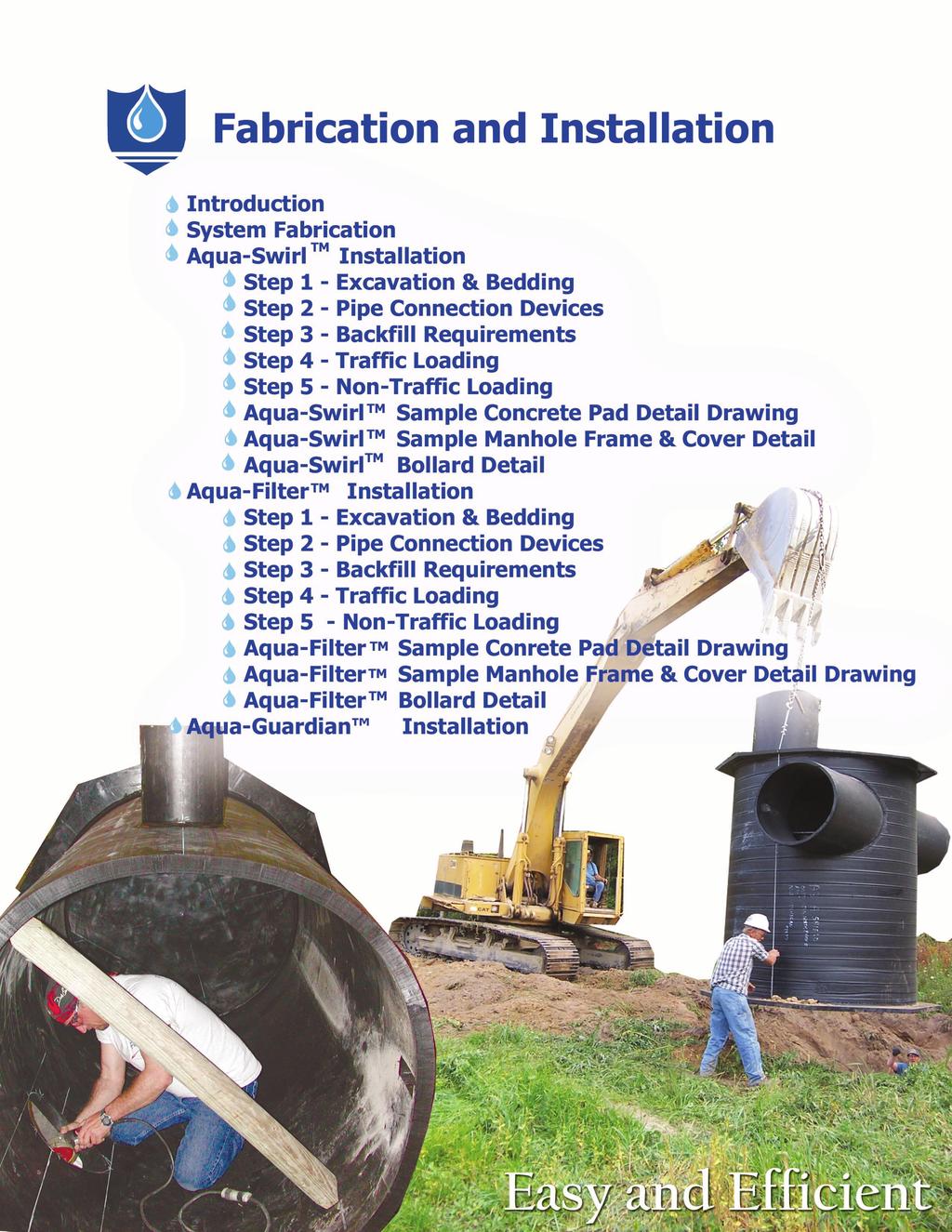
2 Fabrication and Installation Table of Contents HDPE AQUASHIELD PRODUCTS 2 Fabrication and Installation 2 System Fabrication 3 Aqua-Swirl Installation 4 Step 1 Excavation and Bedding 4 Step 2 Pipe Connection Devices 4 Step 3 Backfill Requirements 5 Step 4 Traffic Loading 5 Step 5 Non-Traffic Loading 5 Aqua-Swirl Sample Installation Details 6 Aqua-Swirl Sample Concrete Pad Detail 7 Aqua-Swirl Sample Manhole Detail 8 Aqua-Swirl Bollard Detail 9 Aqua-Filter Installation 10 Step 1 Excavation and Bedding 10 Step 2 Pipe Connection Devices 10 Step 3 Backfill Requirements 11 Step 4 Traffic Loading 11 Step 5 Non-Traffic Loading 11 Aqua-Filter Sample Installation Details 12 Aqua-Filter Sample Concrete Pad Detail 13 Aqua-Filter Sample Manhole Detail 14 Aqua-Filter Bollard Detail 15 Aqua-Guardian Installation Kanasita Drive, Suite B Chattanooga, Tennessee Phone (888) Fax (423)


3 Installation and Fabrication HDPE AquaShield Products Fabrication and Installation Throughout this section and in our individual product specifications, references will be made to specific ASTM standards for the manufacturing and the installation of the AquaShield products. Quality control is a high priority within AquaShield. That is why all of the patented products are fabricated, inspected and tested before leaving for the job site. The AquaShield systems are a modular design and constructed to facilitate the installation process. Because each system is constructed of High-Density Polyethylene (HDPE), even the largest units can be off-loaded and installed without the use of a crane or other special lifting equipment. Lifting cables are provided on each Aqua-Swirl and Aqua-Filter, allowing an excavator or backhoe to maneuver and position the system. Furthermore, the systems can be stored on the job site following offloading to accommodate changing schedules. Stub-outs for the inlet and outlet are part of the modular design of the Aqua-Swirl and Aqua-Filter, which allows the contractor to attach the pipes to the Lifting cable for installation inlet and outlet of the Stormwater Treatment System with couplings. The Aqua-Guardian is also completely assembled at the factory and ready for installation after removing the shipping protection. Typically, an AquaShield representative is present on-site to assist in the installation process. Both the Aqua-Swirl and the Aqua-Filter come with risers and custom manhole frames and covers. Delivery is typically less than four weeks from final approval of shop drawings. 2


4 Installation and Fabrication System Fabrication All internal and structural components of the AquaShield line of stormwater treatment products are constructed with HDPE material, which is strong, resilient, extremely tough and durable. HDPE is also resistant to chemicals and corrosion, and can withstand high sodium conditions. Furthermore, HDPE has a density that is one-eighth that of steel, so it is both A hot air welded joint lightweight and flexible. All connections are normally joined by heat/butt fusion, extrusion, and hot air welding techniques which produces fully restrained joints with zero leakage. Unlike other stormwater treatment systems that are constructed of concrete enclosures and field assembled components, the AquaShield line of stormwater treatment products are fully assembled at the factory allowing for easy on-site handling, installation and connection to the storm drainage structure. AquaShield handles all workmanship to ensure consistent quality of our patented systems. Our line of stormwater treatment products arrive at the job site ready for installation and use. An Aqua-Swirl being transported from fabrication 3


5 Installation and Fabrication Aqua-Swirl Installation Routine installation steps for the Aqua-Swirl units involve preparation and excavation of the area that is to contain the Aqua-Swirl. This includes grading, leveling, and compacting the base material before lowering the unit into the excavation and connecting the Aqua-Swirl inlet and outlet stub-outs with appropriate pipe couplings. Prior to shipping, the purchasing contractor provides written confirmation to install AquaShield products in accordance with manufacturer's specifications. Step 1 Excavation and Bedding The trench and trench bottom shall be constructed in accordance with ASTM D 2321, 6, Trench Excavation, and Section 7, Installation. The excavation pit is best positioned slightly offset of the center line of the incoming drain pipe trench because of the tangential inlet pipe connecting to the Aqua-Swirl. The Aqua-Swirl shall be installed on a stable base consisting of 12 inches of Class I stone materials (angular, crushed stone or rock, crushed gravel; large void content, containing little or no fines) as defined by ASTM D 2321, Section 5, Materials; and, compacted to 95% proctor density. All required safety precautions for Aqua- Swirl installation are the responsibility of the contractor. On-site excavation Step 2 Pipe Connection Devices Couplings to and from the Aqua-Swirl shall be supplied by the contractor and shall be Fernco, Mission or equal type flexible boot with stainless steel tension bands or equal. Using a metal sheer guard will protect the flexible connector. The coupling between the Aqua- Swirl and the pipe 4


6 Installation and Fabrication Step 3 Backfill Requirements Backfill materials shall be Class I or II stone materials, (well graded gravels, gravelly sands; content, containing little or no fines) as defined by ASTM D 2321, Section 5, Materials; and, compacted to 90% proctor density. Class I materials are preferred. Backfill and bedding materials shall be free of debris. Backfilling shall conform to ASTM F 1759, Section 4.2, Design Assumptions. Backfill shall extend at least 3.5 feet beyond the edge of the Aqua-Swirl and for the full height to sub-grade and extend laterally to undisturbed soils. Class I backfill material around the Aqua-Swirl Sufficient backfill shall be placed over components prior to using heavy compaction or construction equipment to prevent damage. Support shall be provided for vertical risers as commonly found at service connections, cleanouts, and drop manholes to preclude vertical or lateral movement. Step 4 Traffic Loading A reinforced concrete pad shall be placed over the entire Aqua-Swirl when subject to H-20 (or greater) traffic loading. The pad shall extend no less than 12 inches beyond the outside diameter of the Aqua-Swirl. A professional engineer shall provide final approval of the design of the concrete pad and the calculations must be included in the submittal. Traffic rated foundry rims and covers shall be installed such that no contact is made between the HDPE access riser and cast iron frame. A reinforced concrete pad for H-20 traffic loading Step 5 Non-Traffic Loading Bollards shall be placed around access risers in non-traffic areas to prevent inadvertent loading by maintenance vehicles. 5
7 Installation and Fabrication Aqua-Swirl Sample Installation Details Aqua-Swirl Sample Concrete Pad Detail Aqua-Swirl Sample Manhole Detail Aqua-Swirl Bollard Detail 6
8
9
10
11
12
13


14 Installation and Fabrication Aqua-Filter Installation Normal installation steps for the Aqua-Filter units involve preparation and excavation of the area that is to contain the Aqua- Filter. This includes grading, leveling and compacting the base material before lowering the unit into the excavation and connecting the Aqua-Filter inlet and outlet stub-outs with appropriate pipe couplings. Prior to shipping, the purchasing contractor provides written confirmation to install AquaShield products in accordance with manufacturer's specifications. An Aqua-Filter system ready to be installed Step 1 Excavation and Bedding The trench and trench bottom shall be constructed in accordance with ASTM D 2321, Section 6, Trench Excavation, and Section 7, Installation. The HDPE filtration system shall be installed on a stable base consisting of 12-inches of Class I stone materials (angular, crushed stone or rock, crushed gravel; large void content, containing little or no fines) as defined by ASTM D 2321, Section 5, Materials, and compacted to 95% proctor density. Additional bedding shall be tamped around the under-center of the filter chamber up to the springline to provide adequate support. All required safety precautions for the system installation are the responsibility of the contractor. Step 2 Pipe Connection Devices Couplings to and from the Aqua-Filter shall be supplied by the contractor and shall be Fernco, Mission or equal type flexible boot with stainless steel tension bands or equal. A metal sheer guard should be used when available. The manufacturer shall supply the coupling to connect the Aqua-Swirl to the filtration chamber. The coupling between the Aqua- Swirl and the filtration chamber of the Aqua-Filter system 7


15 Installation and Fabrication Step 3 Backfill Requirements Backfill materials shall be Class I or II stone materials, (well graded gravels, gravelly sands; containing little or no fines) as defined by ASTM D 2321, Section 5, Materials, and compacted to 90% proctor density. Class I materials are preferred. Backfill and bedding materials shall be free of debris. Backfilling shall conform to ASTM F 1759, Section 4.2, Design Assumptions. Backfill Class I backfill surrounding the Aqua-Filter system shall extend at least 3.5 feet beyond the edge of the stormwater filtration system and for the full height to sub-grade and extend laterally to undisturbed soils. Sufficient backfill shall be placed over components prior to using heavy compaction or construction equipment to prevent damage. Support shall be provided for vertical risers as commonly found at service connections, cleanouts, and drop manholes to preclude vertical or lateral movement. Step 4 Traffic Loading A reinforced concrete pad shall be placed over the entire system when subject to H-20 (or greater) traffic loading. The pad shall extend no less than 12 inches beyond the outside diameter of the Aqua-Swirl and filtration chamber on all sides. A professional engineer shall provide final approval of the design of the concrete pad and the calculations must be included in the submittal. Traffic rated foundry rims and covers shall be installed such that no contact is made with access risers. The installation of a reinforced concrete pad for H-20 traffic loading Step 5 Non-Traffic Loading Bollards shall be placed around access risers in non-traffic areas to prevent inadvertent loading by maintenance vehicles. 8

16 Installation and Fabrication Aqua-Filter Sample Installation Details Aqua-Filter Sample Concrete Pad Detail Aqua-Filter Sample Manhole Detail Aqua-Filter Deadman Detail Aqua-Filter Bollard Detail 14
17
18
19
20


21 Installation and Fabrication Aqua-Guardian Installation Installation is a simple process of removing the surface grate cover and lowering the Aqua-Guardian into the catch basin. Due to the lightweight nature of HDPE, the Aqua-Guardian units can be installed without the need for special lifting equipment. However, removal and handling of the storm grate cover may require lifting equipment due to its weight and size. The surface grate over an Aqua-Guardian unit The stainless steel support collar on the Aqua-Guardian is custom fitted to the inside the surface grate s frame. The flange on the stainless steel support collar will rest on the same rim that receives the surface grate cover. Once the insert is properly seated on the metal rim, replace the grate cover. The simple Aqua-Guardian installation without equipment 10
Aqua-Swirl Stormwater Treatment System
 Aqua-Swirl Stormwater Treatment System Inspection and Maintenance Manual AquaShield, Inc. 2705 Kanasita Drive, Chattanooga, TN 37343 Phone: (423) 870-8888 Fax: (423) 826-2112 Email: info@aquashieldinc.com
Aqua-Filter Table of Contents
 Aqua-Filter Table of Contents AQUA-FILTER 2 Stormwater Filtration Systems 2 System Operation 3 Step 1: Pretreatment 4 Step 2: Filtration 4 Aqua-Filter Filter Media 4 Installation 5 Buoyancy 5 Traffic Loading
Table of Contents AQUA-SWIRL 2
 Table of Contents AQUA-SWIRL 2 STORMWATER TREATMENT SOLUTIONS 2 System Operation 2 Custom Applications 4 Retrofit Applications 4 Installation 5 Buoyancy 5 Traffic Loading 6 Inspection and Maintenance 6
Aqua-Swirl Stormwater Treatment System
 Aqua-Swirl Stormwater Treatment System Inspection and Maintenance Manual AquaShield TM, Inc. 2733 Kanasita Drive Suite 111 Chattanooga, TN 37343 Toll free (888) 344-9044 Phone: (423) 870-8888 Fax: (423)
Aqua-Swirl Stormwater Treatment System
 Aqua-Swirl Stormwater Treatment System Inspection and Maintenance Manual AquaShield TM, Inc. 2705 Kanasita Drive Chattanooga, TN 37343 Toll free (888) 344-9044 Phone: (423) 870-8888 Fax: (423) 826-2112
System Maintenance Table of Contents
 Table of Contents AQUASHIELD PRODUCTS 2 System Maintenance 2 Inspection 3 Aqua-Swirl Maintenance 3 Aqua-Swirl Inspection Procedure 3 Aqua-Swirl Cleanout Procedure 4 Aqua-Swirl Inspection Data Sheet 5 Aqua-Swirl
MATERIALS STORM DRAIN PIPE TABLE OF CONTENTS
 TABLE OF CONTENTS 1. TYPES OF STORM DRAIN PIPE AND JOINTS...2 2. MANHOLES, CATCH BASINS AND INLETS BLOCK AND BRICK...3 3. PRECAST MANHOLES, CATCH BASINS AND INLETS...4 4. STORM DRAIN STUBS...4 5. STORM
Bio-Filter TM Stormwater Biofiltration System
 Bio-Filter TM Stormwater Biofiltration System Inspection and Maintenance Manual March 2017 AquaShield, TM Inc. 2733 Kanasita Drive, Suite 111 Chattanooga, TN 37343 Phone: (423) 870-8888 Fax: (423) 826-2112
SECTION 39 - MANHOLES TABLE OF CONTENTS 39-1 GENERAL PRECAST CONCRETE MANHOLES
 Section SECTION 39 - MANHOLES TABLE OF CONTENTS 39-1 GENERAL... 39-1 39-2 PRECAST CONCRETE MANHOLES... 39-1 39-2.01 Precast Concrete Storm Drain Manholes... 39-1 39-3 SADDLE MANHOLES... 39-2 39-3.01 Saddle
MANHOLES, VAULTS AND CATCH BASINS SECTION A. Section Soil and Aggregate Materials. C. Section Storm Drainage Systems
 SECTION 02607-1 1.0 GENERAL 1.1 SCOPE: A. This section covers the work necessary for the construction of sanitary and storm system manholes, catch basins, and miscellaneous concrete structures complete.
GWINNETT COUNTY STORM SEWER PIPE STANDARDS
 1.0 Standard Specifications GWINNETT COUNTY STORM SEWER PIPE STANDARDS 1.1 Unless otherwise specifically set forth herein or in the Gwinnett County Standard Drawings, all of the materials, methods of the
PERMANENT PAVEMENT REPAIR NO SCALE
 SAWCUT EXISTING PAVEMENT 2" BITUMINOUS CONCRETE SURFACE COURSE, CLASS 2 (MIN) CLEAN EDGE PRIOR TO PAVING AND PAINT WITH LIQUID BITUMEN. INSTALL SEALANT OVER JOINT UPON COMPLETION 2" BITUMINOUS CONCRETE
PASSAIC COUNTY TECHNICAL INSTITUTE CCA 1422 NEW S.T.E.M. BUILDING 2017
 SECTION 02630 - STORM DRAINAGE PART 1 - GENERAL 1.1 RELATED DOCUMENTS A. Drawings and general provisions of the Contract, including General and Supplementary Conditions and Division 01 Specification Sections,
SECTION STORM SEWER COLLECTION SYSTEM
 SECTION 02722 STORM SEWER COLLECTION SYSTEM PART 1 GENERAL 1.01 SUMMARY A. This section addresses the installation of storm sewer collection mains and includes the acceptable products, materials, and construction
SECTION XXXX POLYMER CONCRETE PUMP STATIONS
 SECTION XXXX POLYMER CONCRETE PUMP STATIONS PART 1 GENERAL 1.1 SUMMARY A. This specification shall govern for the furnishing of all work necessary for installation of polymer concrete pump stations to
NORTHWESTERN UNIVERSITY PROJECT NAME JOB # ISSUED: 03/29/2017
 SECTION 33 3400 STORM UTILITY DRAINAGE PIPING PART 1 - GENERAL 1.1 RELATED DOCUMENTS A. Drawings and general provisions of the Contract, including General and Supplementary Conditions and Division 01 Specification
SECTION STORM UTILITY DRAINAGE PIPING PART 1 - GENERAL 1.1 SUMMARY 1.2 SUBMITTALS 1.3 PROJECT CONDITIONS
 SECTION 334100 - STORM UTILITY DRAINAGE PIPING PART 1 - GENERAL 1.1 SUMMARY Section Includes: 1. Pipe and fittings. 2. Drain Basin. 3. De-chlorination tablet feeder. 4. Non-pressure transition couplings.
New Fulton State Hospital Energy Control Center and Services Building (ECC/SVC) Project Number: M
 Project Number: M") SECTION 334100 - STORM UTILITY DRAINAGE PIPING PART 1 -GENERAL 1.1 RELATED DOCUMENTS A. Drawings and general provisions of the Contract, including General and Supplementary Conditions and Division 01 Specification
SECTION 334100 - STORM UTILITY DRAINAGE PIPING PART 1 -GENERAL 1.1 RELATED DOCUMENTS A. Drawings and general provisions of the Contract, including General and Supplementary Conditions and Division 01 Specification
B. Fiberglass for construction in back lot easements placed on cast-in-place base.
 Section 02083 PART 1 G E N E R A L 1.01 SECTION INCLUDES A. Fiberglass manholes for unpaved areas placed on top of a precast base to form a manhole. B. Fiberglass for construction in back lot easements
SECTION STORM SEWER PIPE
 SECTION 4200 - STORM SEWER PIPE 4200.1 SCOPE: This section covers the requirements for all labor, equipment and materials for the installation of storm sewers pipes. Trenching guidelines are provided in
NORTH HARRIS COUNTY REGIONAL WATER AUTHORITY CAST-IN-PLACE. Section CAST-IN-PLACE CONCRETE MANHOLES
 PART 1 GENERAL 1.01 SUMMARY This Section includes: Section 02081 CAST-IN-PLACE A. Cast-in-place concrete manholes for sanitary sewers and storm sewers, including box sewers. B. Pile-supported concrete
This type of masonry shall consist of brick laid in full beds of cement mortar.
 SECTION 11.0 DRAINAGE STRUCTURES 11.01 Scope of Work This item shall consist of installation and construction of storm drainage pipes, culverts, basins, headwalls, manholes, junction boxes, head ditches,
SECTION DOWNSTREAM DEFENDER
 SECTION 02631 DOWNSTREAM DEFENDER PART 1 - GENERAL 1.01 SCOPE A. Work described in this section includes furnishing all labor, equipment, materials, tools and incidentals required for a complete and operable
SEWER FORCE MAIN HDPE PIPE
 SECTION 15150 SEWER FORCE MAIN HDPE PIPE PART 1: GENERAL 1-1 DESCRIPTION: This specification governs the material, pipe, fittings, joining methods and general construction practice for High Density Polyethylene
The Most Advanced Name in Water Management Solutions TM. The most cost-effective slotted and trench surface drain systems.
 The Most Advanced Name in Water Management Solutions TM The most cost-effective slotted and trench surface drain systems. A sensible alternative to metal and concrete Since 1987, Duraslot surface drains
SECTION MANHOLES AND STRUCTURES. A. Section Includes: 1. Manholes for water, storm drain and sanitary sewer systems.
 SECTION 33 05 13 MANHOLES AND STRUCTURES PART 1 GENERAL 1.1 SUMMARY A. Section Includes: 1. Manholes for water, storm drain and sanitary sewer systems. B. Related Sections: 1. Section 03 20 00 - Concrete
San Antonio Water System Standard Specifications for Construction ITEM NO. 853 SANITARY SEWER GLASS-FIBER REINFORCED POLYESTER (FRP) MANHOLES
 MANHOLES") ITEM NO. 853 SANITARY SEWER GLASS-FIBER REINFORCED POLYESTER (FRP) MANHOLES 853.1 DESCRIPTION: This item shall govern the construction of FRP sanitary sewer complete in place and the material therein,
ITEM NO. 853 SANITARY SEWER GLASS-FIBER REINFORCED POLYESTER (FRP) MANHOLES 853.1 DESCRIPTION: This item shall govern the construction of FRP sanitary sewer complete in place and the material therein,
SECTION 39 - MANHOLES TABLE OF CONTENTS
 Section SECTION 39 - MANHOLES TABLE OF CONTENTS Page 39-1 GENERAL... 39.1 39-2 CONCRETE MANHOLES... 39.1 39-2.01 NOT USED... 39.1 39-2.02 Concrete Storm Drain Manholes... 39.1 39-3 SADDLE SEWER MANHOLES...
SUPPLEMENTARY SECTION: STANDARD SPECIFICATIONS PAGE 1 STORMWATER MAINS & CULVERTS MAY 2018
 STANDARD SPECIFICATIONS PAGE 1 STORMWATER MAINS & CULVERTS MAY 2018 PART 1 - GENERAL... 2 1.1 Work Included... 2 1.2 Related Sections... 2 1.3 Reference Standards... 2 1.4 Shop Drawings... 3 1.5 Certificates...
Weholite LIGHTWEIGHT PIPE SYSTEM
 Weholite LIGHTWEIGHT PIPE SYSTEM The lightweight pipe that takes a heavier load Weholite pipe is large diameter, profile wall pipe made from highdensity polyethylene (HDPE) resin, which is manufactured
A. This Section includes gravity-flow, nonpressure storm drainage outside the building, with the following components:
 SECTION 334100 - STORM UTILITY DRAINAGE PIPING PART 1 - GENERAL 1.I RELATED DOCUMENTS A. Drawings and general provisions of the Contract, including General and Supplementary Conditions and Division 1 Specification
GUIDELINES FOR INSTALLATION OF ON-SITE SEWAGE SYSTEMS
 UTAH COUNTY HEALTH DEPARTMENT Div. of Environmental Health 151 South University Avenue, Provo 84601 (801) 851-7525 FAX 851-7521 GUIDELINES FOR INSTALLATION OF ON-SITE SEWAGE SYSTEMS This is intended to
SECTION STORM DRAINAGE SYSTEM Excavating, Backfilling, and Compaction for Utilities Cast-in-place Concrete.
 SECTION 02720 STORM DRAINAGE SYSTEM PART 1 GENERAL 1.01 SUMMARY A. Related Sections: 1. 02221 - Excavating, Backfilling, and Compaction for Utilities. 2. 03300 - Cast-in-place Concrete. 1.02 REFERENCES
(SIZE) MANHOLES CATCH BASINS AND DITCH INLETS -Item No. ADJUSTING AND REBUILDING MANHOLES, CATCH BASINS AND DITCH INLETS - Item No.
 MANHOLES CATCH BASINS AND DITCH INLETS -Item No. ADJUSTING AND REBUILDING MANHOLES, CATCH BASINS AND DITCH INLETS - Item No.") (SIZE) MANHOLES CATCH BASINS AND DITCH INLETS -Item No. ADJUSTING AND REBUILDING MANHOLES, CATCH BASINS AND DITCH INLETS - Item No. Special Provision No. 407S06 July 2010 Aggregate Requirements, Lift Rings,
(SIZE) MANHOLES CATCH BASINS AND DITCH INLETS -Item No. ADJUSTING AND REBUILDING MANHOLES, CATCH BASINS AND DITCH INLETS - Item No. Special Provision No. 407S06 July 2010 Aggregate Requirements, Lift Rings,
SECTION STORM DRAINAGE
 SECTION 02720 STORM DRAINAGE PART 1 - GENERAL 1.01 WORK INCLUDED A. Trenching and other excavation. B. Ground water control. C. Pipe bedding. D. Installation of storm drains and appurtenances. E. Installation
FS-DUO. Wastewater Flow Distributor Technical Data. Submittal Special Precautions Specifications Installation. (62.2 cm) (62.2 cm)
 (62.2 cm)") Wastewater Flow Distributor Technical Data Submittal Special Precautions Specifications Installation 24½" (62.2 cm) 12½" (31.8 cm) 24½" (62.2 cm) (30.5 cm) SUBMITTAL STANDARD: 4" plain end inlet/outlet
Wastewater Flow Distributor Technical Data Submittal Special Precautions Specifications Installation 24½" (62.2 cm) 12½" (31.8 cm) 24½" (62.2 cm) (30.5 cm) SUBMITTAL STANDARD: 4" plain end inlet/outlet
SPECIAL SPECIFICATION 4653 Polypropylene Pipe
 2004 Specifications CSJ 2158-01-013, Etc. SPECIAL SPECIFICATION 4653 Polypropylene Pipe 1. Description. Furnish and install polypropylene pipe for constructing polypropylene pipe culverts or polypropylene
SEPTIC TANK CONSTRUCTION GUIDELINES
 SEPTIC TANK CONSTRUCTION GUIDELINES Septic tank for this airport will be designed/ built by the general contractor of the building facilities. At the time of the project design, availability of a septic
SV24. Submittal Special Precautions Specifications Installation. 12½" (31.8 cm) 12½" (31.8 cm) 12" (30.5 cm) 12" (30.5 cm) 12" (30.
 12½ (31.8 cm) 12 (30.5 cm) 12 (30.5 cm) 12 (30.") Wastewater Sampling Port Technical Data Submittal Special Precautions Specifications Installation 16½" (31.8 (41.9 cm) 8" (20.3 cm) -L -O SUBMITTAL STANDARD: 4" plain end inlet/outlet Highway traffic load
Wastewater Sampling Port Technical Data Submittal Special Precautions Specifications Installation 16½" (31.8 (41.9 cm) 8" (20.3 cm) -L -O SUBMITTAL STANDARD: 4" plain end inlet/outlet Highway traffic load
SECTION PRECAST CONCRETE MANHOLES
 SECTION 03 48 10 PRECAST CONCRETE MANHOLES PART 1: GENERAL 1.01 SECTION INCLUDES A. Precast concrete manholes for sanitary sewers and water lines or as indicated on the Drawings. B. Precast concrete sanitary
***************************************************************************************************************
 02720 STORM DRAINAGE SYSTEM *************************************************************************************************************** SPECIFIER: CSI MasterFormat 2004 number 33 40 00. ***************************************************************************************************************
Technical Data Sheet NEC/GRAN/95:01
 Technical Data Sheet NEC/GRAN/95:01 Installation Guidance Notes Granular Surround Note : These guidance notes refer only to the installation of Granular surround underground tanks. These guidance notes
SECTION CS-2. TRENCH EXCAVATION CONSTRUCTION STANDARDS
 SECTION CS-2. TRENCH EXCAVATION CONSTRUCTION STANDARDS CS-2-01. GENERAL: Trench excavation shall conform with the City Standard Specifications. In general a trench is defined as an excavation in which
SECTION 92 METER LIFT ASSEMBLIES
 2019 - SECTION 92 METER LIFT ASSEMBLIES 92.1 GENERAL This section of the specifications shall form a part of the contract documents and should be read in conjunction with them. The work shall include the
SPECIAL SPECIFICATION 4425 Thermoplastic Pipe
 2004 Specifications CSJ 0264-07-028 SPECIAL SPECIFICATION 4425 Thermoplastic Pipe 1. Description. Furnish and install thermoplastic pipe for constructing thermoplastic pipe culverts or thermoplastic storm
PERMEABLE INTERLOCKING PAVERS
 PERMEABLE INTERLOCKING PAVERS PART 1 - GENERAL 1.01 SECTION INCLUDES A. Subgrade Preparation B. Placement of Storage Aggregate C. Placement of Filter Aggregate D. Placement of Bedding Course E. Placement
Section 403. DRAINAGE STRUCTURES
 403.01 Section 403. DRAINAGE STRUCTURES 403.01. Description. This work consists of adjusting, constructing, or temporarily lowering drainage structures and cleaning existing drainage structures and leads
1. Division 01 Section General Requirements - Temporary Facilities and Controls. 2. Division 31 Section Earthwork.
 PAGE 334000-1 SECTION 334000 PART 1 - GENERAL 1.1 RELATED DOCUMENTS A. Drawings and general provisions of the Contract, including General and Supplementary Conditions and Division 01 Specification sections,
VALLECITOS WATER DISTRICT SECTION PRECAST REINFORCED CONCRETE MANHOLES
 PART 1 GENERAL 1.1 DESCRIPTION A. This section includes materials, testing, and installation of precast concrete manholes, manhole bases, manhole frames, and covers. 1.2 RELATED WORK SPECIFIED ELSEWHERE
TABLE OF CONTENTS
 DIVISION 33: SEWER AND SEPTIC SYSTEMS 33 3633 UTILITY SEPTIC TANK DRAINAGE FIELD TABLE OF CONTENTS 33 0000-1 SECTION 33 3633-- UTILITY SEPTIC TANK DRAINAGE FIELD PART 1 - GENERAL 1.1 SUMMARY A. Includes
SECTION STORM DRAIN
 PART 1 - GENERAL 1-01 SECTION INCLUDED A. Furnishing and installing storm drainage facilities, including pipe, cleanout, manhole structures and inlet structures. 1-02 RELATED SECTIONS A. Division 00 Contract
Gravity Wall. A force to be reckoned with... Gravity (SRW) segmental retaining wall systems are structures
 segmental retaining wall systems are structures") A force to be reckoned with... Gravity (SRW) segmental retaining wall systems are structures lower in height that use the FrogStone unit weight combined with gravel core infill to resist earth pressures
A force to be reckoned with... Gravity (SRW) segmental retaining wall systems are structures lower in height that use the FrogStone unit weight combined with gravel core infill to resist earth pressures
Underground Exhaust System
 Operation and Maintenance Manual Underground Exhaust MONOXIVENT - SOURCE CAPTURE SYSTEMS - info@ Oct. - 2015 Underground Duct Construction Standards 1. Dig trench depth to allow for minimum distance from
SECTION STORM DRAINAGE UTILITIES. B. Section : Site Restoration and Rehabilitation
 SECTION 33 40 00 STORM DRAINAGE UTILITIES 1. PART 1 GENERAL 1.1 RELATED WORK A. Section 31 23 00: Excavation and Fill B. Section 32 00 01: Site Restoration and Rehabilitation C. Special Conditions for
MagnumStone Specifications Gravity
 MagnumStone Specifications Gravity SPECIFICATION FOR MAGNUMSTONE GRAVITY MECHANICALLY STABILIZED EARTH SYSTEM PART 1: GENERAL.01Description The work consists of supplying and installing all aspects of
CHAPTER 200 STORM SEWER CONSTRUCTION STANDARDS
 CHAPTER 200 STORM SEWER CONSTRUCTION STANDARDS Storm Sewer System: 1. Detention/retention of stormwater runoff shall be provided in accordance with the requirements of the DuPage County Countywide Stormwater
NORTH HARRIS COUNTY REGIONAL WATER AUTHORITY. Section PRECAST CONCRETE MANHOLES
 PART 1 GENERAL 1.01 SUMMARY This Section includes: Section 02082 A. Precast concrete manholes for sanitary sewers, storm sewers and water lines. B. Precast concrete sanitary sewer manholes with PVC liner
TCC/SHORE TRANSIT BUS MAINTENANCE FACILITY - PHASE II
 SECTION 221313 - FACILITY SANITARY SEWERS PART 1 - GENERAL 1.1 RELATED DOCUMENTS A. Drawings and general provisions of the Contract, including General and Supplementary Conditions and Division 01 Specification
ITEM NO. 853 SANITARY SEWER GLASS-FIBER REINFORCED POLYESTER (FRP) MANHOLES
 MANHOLES") ITEM NO. 853 SANITARY SEWER GLASS-FIBER REINFORCED POLYESTER (FRP) MANHOLES 853.1 DESCRIPTION: This item shall govern the construction of FRP sanitary sewer complete in place and the material therein,
ITEM NO. 853 SANITARY SEWER GLASS-FIBER REINFORCED POLYESTER (FRP) MANHOLES 853.1 DESCRIPTION: This item shall govern the construction of FRP sanitary sewer complete in place and the material therein,
SaniTite. HP Sewer Pipe 300 mm 750 mm
 SaniTite HP Sewer Pipe 300 mm 750 mm sanitite HP SEWER Pipe 300 mm 750 mm Certified to CSA B182.13 A new addition to our proven line of pipe products, SaniTite HP (High Performance) couples advanced Polypropylene
Facility Sanitary Sewers
 University of New Hampshire University of New Hampshire Scholars' Repository Division 22 Plumbing Chapter 5 Technical Construction and Renovation Standards 4-23-2015 221313 - Facility Sanitary Sewers Sandra
TRENCHLESS CONSTRUCTION (BORING, JACKING, AND TUNNELING)
") PART 1 - GENERAL TRENCHLESS CONSTRUCTION (BORING, JACKING, AND TUNNELING) 1.01 SECTION INCLUDES A. Trenchless Installation of Carrier Pipe with Casing Pipe B. Trenchless Installation of Carrier Pipe without
PART 1 - GENERAL TRENCHLESS CONSTRUCTION (BORING, JACKING, AND TUNNELING) 1.01 SECTION INCLUDES A. Trenchless Installation of Carrier Pipe with Casing Pipe B. Trenchless Installation of Carrier Pipe without
TYPE "A" CATCH BASIN
 27" 1.67' TO BACK OF CURB LINE TOP OF GRATE ELEV. - SEE PLAN NEENAH CASTING R-3250-BV OR APPROVED EQUAL. "INFI SHIELD" SEAL OR APPROVED EQUAL RINGS (2 MIN., 1' MAX. OF RINGS AND MORTAR). PLASTER OUTSIDE,
SECTION A-A NTS. Figure 4.1 Alternative Flow Dispersal Trench NOTES:
 Figure 4.1 Alternative Flow Dispersal Trench NOTES: galvanized bolts 2" x 12" pressure treated grade board 2" x 2" notches 18" O.C. *20% max 12" min. 36" max 1' - 6" min *20% max 4" x 4" support post clean
1510 STORM DRAINAGE UTILITIES
 SECTION 334000 STORM DRAINAGE UTILITIES PART 1 - GENERAL 1.1 RELATED DOCUMENTS A. Drawings and general provisions of the Contract, including General and Special Conditions and Division 1 Specification
Uwall UNIVERSAL CONSTRUCTION MANUAL
 Uwall UNIVERSAL Retaining Wall System CONSTRUCTION MANUAL TM President s Letter CSI is a leader in its industry supplying precast infrastructure products throughout New England and beyond since 1972, developing
SECTION UNDERGROUND ELECTRICAL CONSTRUCTION
 PART 1 - GENERAL 1.1 DESCRIPTION SECTION 26 05 41 UNDERGROUND ELECTRICAL CONSTRUCTION A. This section specifies the furnishing, installation, and connection of precast manholes and pullboxes with ducts
SECTION UTILITY MANHOLES AND STRUCTURES
 SECTION 33 05 14 UTILITY MANHOLES AND STRUCTURES PART 1 GENERAL 1.1 SUMMARY A. Section Includes: 1. Precast reinforced concrete manholes and structures with tongue-and-groove joints with masonry transition
Overview. Advanced Dual Wall Profile Construction. Superior Polypropylene Material
 HP Storm Pipe 12 60 HP STORM pipe 12 60 FOR Storm applications Overview An addition to our proven line of pipe products, HP (High Performance) Storm is a high-performance polypropylene (PP) pipe for gravity-flow
BMP 6.4.4: Infiltration Trench
 BMP 6.4.4: Infiltration Trench An Infiltration Trench is a leaky pipe in a stone filled trench with a level bottom. An Infiltration Trench may be used as part of a larger storm sewer system, such as a
INSTALLATION MANUAL. Hydrodynamic Separation. Bio Clean Environmental Services, Inc. 398 Via El Centro Oceanside, CA 92058
 Hydrodynamic Separation INSTALLATION MANUAL Bio Clean Environmental Services, Inc. 398 Via El Centro Oceanside, CA 92058 www.biocleanenvironmental.com p: 760.433.7640 f: 760.433.3176 INSTALLATION PROCEDURES
CITY OF SCHERTZ TEXAS ENGINEERING AND PUBLIC WORKS
 TEXAS STANDARD CONSTRUCTION NOTES DRWN. BY: DSGN. BY: KJW 1 of 2 *Place geotextile fabric as a permeable seperator to prevent mixing of coarse aggregate and underlying soil. (as needed). 1. GEOTEXTILE
SPECIAL SPECIFICATION 5925 Polyvinyl Cloride (PVC) Sewer Pipe and Fittings
 Sewer Pipe and Fittings") 1993 Specifications CSJ 0144-01-060 SPECIAL SPECIFICATION 5925 Polyvinyl Cloride (PVC) Sewer Pipe and Fittings 1. General. (1) Scope. This Section includes the furnishing, installation, and subsequent
1993 Specifications CSJ 0144-01-060 SPECIAL SPECIFICATION 5925 Polyvinyl Cloride (PVC) Sewer Pipe and Fittings 1. General. (1) Scope. This Section includes the furnishing, installation, and subsequent
TCC/SHORE TRANSIT BUS MAINTENANCE FACILITY PHASE II
 SECTION 334100 - STORM UTILITY DRAINAGE PIPING PART 1 - GENERAL 1.1 RELATED DOCUMENTS A. Drawings and general provisions of the Contract, including General and Supplementary Conditions and Division 01
SECTION PLUMBING DRAINAGE AND CONTAINMENT. Copyright Specialloy Industries Inc. dba Slot Drain Systems - All rights reserved
 SECTION 22 14 00 - PLUMBING DRAINAGE AND CONTAINMENT Copyright 1998-2017 Specialloy Industries Inc. dba Slot Drain Systems - All rights reserved PART 1 GENERAL 1.1 SECTION INCLUDES A. SLOT shaped, non-grated,
San Antonio Water System Specifications for Construction ITEM NO. 853 SANITARY SEWER GLASS-FIBER REINFORCED POLYESTER (FRP) MANHOLES
 MANHOLES") ITEM NO. 853 SANITARY SEWER GLASS-FIBER REINFORCED POLYESTER (FRP) MANHOLES 853.1 DESCRIPTION: This item shall govern the construction of FRP sanitary sewer manholes, complete in place and the materials
ITEM NO. 853 SANITARY SEWER GLASS-FIBER REINFORCED POLYESTER (FRP) MANHOLES 853.1 DESCRIPTION: This item shall govern the construction of FRP sanitary sewer manholes, complete in place and the materials
SECTION FACILITY SANITARY SEWERS
 SECTION 22 13 13 FACILITY SANITARY SEWERS PART 1 - GENERAL 1.1 RELATED DOCUMENTS A. Drawings and general provisions of the Contract, including General and Supplementary Conditions and Division 01 Specification
PRECAST CONCRETE MANHOLES. A. Precast concrete manholes for sanitary sewers, storm sewers, and water lines.
 Section 02082 PART 1 G E N E R A L 1.01 SECTION INCLUDES A. Precast concrete manholes for sanitary sewers, storm sewers, and water lines. B. Precast concrete sanitary sewer manholes with PVC liner where
Section 4 Service Lines
 Section 4 Service Lines A. General 1. A service line is that portion of a sanitary sewer line that extends from the outer building wall or foundation wall to its connection with the sewer lateral at the
SECTION HIGH DENSITY POLYETHYLENE PIPE AND FITTINGS (PRESSURE PIPE)
") SECTION 02623 HIGH DENSITY POLYETHYLENE PIPE AND FITTINGS (PRESSURE PIPE) PART 1 - GENERAL 1.1 SCOPE OF WORK A. Furnish all labor, materials, equipment and incidentals required and install high density
SECTION 02623 HIGH DENSITY POLYETHYLENE PIPE AND FITTINGS (PRESSURE PIPE) PART 1 - GENERAL 1.1 SCOPE OF WORK A. Furnish all labor, materials, equipment and incidentals required and install high density
TECHNICAL SPECIFICATION
 TECHNICAL SPECIFICATION ITEM 02514 MANHOLES 1.0 GENERAL 1.1 SCOPE This section provides for construction of sewer manholes complete in place, including the furnishing and adjusting to grade of an existing
SECTION 1 GENERAL NOTES
 ISSUE DATE NOVEMBER 1st, 2011 SECTION 1 Page List Page Number Page Title COVER COVER GN-01 PAGE 1 GN-02 PAGE 2 GN-03 PAGE 3 GN-04 PAGE 4 GN-05 PAGE 5 GN-06 PAGE 6 GN-07 PAGE 7 : 1. (CCU) STANDARD SPECIFICATIONS
SPECIFICATIONS FOR PRECAST MODULAR BLOCK RETAINING WALL SYSTEM (revised 5/8/7)
") Page 1 of 7 STONE STRONG SYSTEMS SPECIFICATIONS FOR PRECAST MODULAR BLOCK RETAINING WALL SYSTEM (revised 5/8/7) PART 1: GENERAL 1.01 Description A. Work includes furnishing and installing precast modular
Page 1 of 7 STONE STRONG SYSTEMS SPECIFICATIONS FOR PRECAST MODULAR BLOCK RETAINING WALL SYSTEM (revised 5/8/7) PART 1: GENERAL 1.01 Description A. Work includes furnishing and installing precast modular
 SECTION 02605 MANHOLE AND CATCH BASIN STRUCTURES 1.01 SECTION INCLUDES...1 1.02 RELATED REQUIREMENTS...1 1.03 REFERENCES...1 1.04 SUBMITTALS...2 2.01 PRECAST CONCRETE ITEMS...2 2.02 CASTINGS...3 2.03 MORTAR...3
Handling and Installation Instructions
 Handling and Installation Instructions SUPERTANK Water Reclamation Solutions, LLC Unloading and Handling NOTE: It is the responsibility of the installer to follow OSHA safety guidelines during the installation,
THE ADVANTAGES HDPE MANHOLES
 NIC HDPE manholes are custom fabricated for many varied applications including municipal and industrial manholes, sewer and storm water manholes, leach ate collection, sewer lift stations, siphon structures,
Project Location: Various, Anywhere, PA Bid Date: 7/16/ Rock Construction Entrance
 To: Project Name: Bidding Company Site Work Project Contact: Address: Various Phone: Fax: Bid Number: Project Location: Various, Anywhere, PA Bid Date: 7/16/2014 Clarifications: This takeoff does not include
Summary of the 2011 Changes
 The following is a list of amendments to the Residential Site Improvement s, N.J.A.C. 5:21, adopted in 2011. The Notice of Adoption of these changes appeared in the New Jersey Register on May 16, 2011.
San Antonio Water System Standard Specifications for Construction ITEM NO. 848 SANITARY SEWERS
 ITEM NO. 848 SANITARY SEWERS 848.1 DESCRIPTION: This item shall govern the furnishing, installation and jointing of sanitary sewer pipe of the size and type specified by the project's plans and specifications.
G. Shop drawing of wall with all dimensions, details, and finishes. Drawings must include post foundations.
 DURA-CRETE S-SERIES PRECAST CONCRETE WALL SPECIFICATIONS PART 1 GENERAL 1.01 SECTION INCLUDES A. Concrete Screen Wall Description: Work under this item shall consist of furnishing and erecting a wall in
ITEM 706 PIPE SLOPE DRAIN
 AFTER NOVEMBER 1, 2008 ITEM 706 PIPE SLOPE DRAIN 706.1 Description. This work shall consist of the installation of temporary erosion protection and sediment control pipe slope drains, utilized during construction
Nutrient Removing Filtration System
 Nutrient Removing Filtration System Contractor Installation Manual Version 1.0 Suntree Technologies, Inc 798 Clearlake Road, Suite 2 Cocoa, Florida 32922 321.637.7552 www.suntreetech.com info@suntreetech.com
DRAINAGE SOLUTIONS SINCE 1908 NEW PRODUCT BOSS 3000 LARGE DIAMETER STEEL REINFORCED POLYETHYLENE PIPE DURABLE LIGHTWEIGHT COST-EFFECTIVE ARMTEC.
 DRAINAGE SOLUTIONS SINCE 1908 NEW PRODUCT BOSS 3000 LARGE DIAMETER STEEL REINFORCED POLYETHYLENE PIPE DURABLE LIGHTWEIGHT COST-EFFECTIVE ARMTEC.COM BOSS 3000 the next generation of BOSS pipe. BIGGER. STRONGER.
DESIGN GUIDELINES AND TECHNICAL STANDARDS
 DESIGN GUIDELINES AND TECHNICAL STANDARDS Date of Issuance: January 1, 2014 DIVISION 33 UTILITIES SECTION 33 1313 - FACILITY SANITARY SEWERS 1. General: This section includes performance requirements
INDEX FOR SPECIFICATIONS FOR REMOVING CULVERTS AND PLACING CULVERTS SCOPE... 1
 March 2002 No. 400 INDEX FOR SPECIFICATIONS FOR REMOVING CULVERTS AND PLACING CULVERTS 400. 1 SCOPE... 1 400. 2 REMOVING CULVERTS AND TIMBER STRUCTURES 2.1 Concrete and Metal Pipe Culverts... 1 2.2 Structural
2.1.2 Minimum wall thickness shall be 90 mm Frames and covers shall be bitumen coated by dipping.
 1.0 GENERAL 1.1 Scope 2.0 PRODUCTS 1.1.1 The work shall consist of the construction, renovation or the adjustment of manholes and/or catchbasins as detailed on the plans or where designated by the Engineer
TRENCHLESS CONSTRUCTION (BORING, JACKING, AND TUNNELING)
") PART 1 - GENERAL TRENCHLESS CONSTRUCTION (BORING, JACKING, AND TUNNELING) 1.01 SECTION INCLUDES A. Trenchless Installation of Carrier Pipe with Casing Pipe B. Trenchless Installation of Carrier Pipe without
PART 1 - GENERAL TRENCHLESS CONSTRUCTION (BORING, JACKING, AND TUNNELING) 1.01 SECTION INCLUDES A. Trenchless Installation of Carrier Pipe with Casing Pipe B. Trenchless Installation of Carrier Pipe without
Section [ ] Storm Water Treatment Device
![Section [ ] Storm Water Treatment Device](/thumbs/72/67039599.jpg "Section [ ] Storm Water Treatment Device") PART 1 GENERAL Section [ ] Storm Water Treatment Device 01.01.00 Purpose The purpose of this specification is to establish generally acceptable criteria for Storm Water Treatment Devices (SWTD) that treat
PART 1 GENERAL Section [ ] Storm Water Treatment Device 01.01.00 Purpose The purpose of this specification is to establish generally acceptable criteria for Storm Water Treatment Devices (SWTD) that treat
TYPICAL INSTALLATION INSTRUCTIONS
 TYPICAL INSTALLATION INSTRUCTIONS Environment One Grinder Pump Feature Identification 1. Grinder Pump Basin High density polyethylene (HDPE) 2. Accessway Cover Painted Steel 3. Electrical Quick Disconnect
DARTMOUTH COLLEGE DESIGN January 3, 2012 & CONSTRUCTION GUIDELINES
 SECTION 15420 DRAINAGE AND VENT SYSTEMS PART 1 DESIGN DIRECTIVES 1.1 DESIGN CRITERIA A. All cleanouts above finished (accessible and non-accessible) ceilings shall be extended to the floor above. B. Do