NPTEL Course GROUND IMPROVEMENT USING MICROPILES
|
|
|
- Amelia Nicholson
- 6 years ago
- Views:
Transcription
1 Lecture 22 NPTEL Course GROUND IMPROVEMENT USING MICROPILES Prof. G L Sivakumar Babu Department of Civil Engineering Indian Institute of Science Bangalore gls@civil.iisc.ernet.in
2 Contents Introduction Classification 1. Based on Design criteria 2. Based on Construction type Advantages of micropiles Applications Design of micro piles using FHWA guidelines Design Example
3 Introduction Micropiles were conceived in Italy in the early 195Os, in response to the demand for innovative techniques for underpinning historic buildings and monuments that had sustained damage during World War II. A reliable method was required to support structural loads with minimal movement and for installation in access-restrictive environments with minimal disturbance to the existing structure. An Italian specialty contractor called Fondedile, and Dr. Fernando Lizzi developed the technique. The use of micropiles has grown significantly and have been used mainly as elements for foundation support to resist static and seismic loading conditions, and as in-situ reinforcements for slope and excavation stability.
4 Piles are divided in two general types as a) Displacement piles b) Replacement piles Displacement piles are members that are driven or vibrated into the ground, there by displacing the surrounding soil laterally during installation. Replacement piles are placed or constructed with in a previously drilled borehole, thus replacing the excavated ground. A Micropile is a small diameter (< 300mm), drilled and grouted pile that is typically reinforced.

5 1) Based on Design Application Case 1: Micropile elements, which are loaded directly & where the pile reinforcement resists the majority of the applied load. Classification of Micropiles Case 2: Micropile elements circumscribe and internally reinforce the soil to make a reinforced soil composite that resists the applied load. Fig1(a): Drilled Micropiles under a building
6
7 For Structural support (Case 1) a) New Foundations Applications b) Under pinning of existing structures c) Seismic retrofitting of existing structures d) Scour protection e) Earth retention In situ Reinforcement (Case 2) a) Slope Stabilization b) Earth retention c) Ground strengthening and protection d) Settlement reduction

8 Classical arrangement of root piles for underpinning

9 Typical network of Reticulated Micropiles
")
10 CASE 1 Micropiles (Directly Loaded)

11 CASE 2 Micropiles-Reticulated Pile Network with Reinforced Soil Mass Loaded or Engaged

12 CASE1 Micropile arrangements

13 CASE 2 Micropile arrangements
14 2) Based on Construction type The method of grouting is generally the most sensitive construction control over grout/ground bond capacity. Grout-to-grout capacity varies with the grouting method. a) Type A: Gravity Grout b) Type B: Pressure through Casing c) Type C: Single Global Post Grout d) Type D: Multiple Repeatable Post Grout

15 Type A: Here the grout is placed under gravity head only using sand-cement motors or neat cement. Type B: In this type neat cement grout is placed in to the hole as the temporary steel casing is with drawn. Injection pressures varies from 0.5 to 1.0 MPa. The pressure is limited to avoid fracturing of the surrounding ground. Fig1(b): Micropile classification based on type of grouting.
16 Type C: This is done in two step process: 1) As of Type A 2) Prior to hardening of the primary grout, similar grout is injected one time via a sleeve grout pipe at pressure of at least 1.0MPa. Type D: This is done in two step process of grouting similartotypecwithmodificationstostep2where the pressure is injected at a pressure of 2.0 to 8.0 MPa:
17 Advantages of Micropiles Micropiles are often used to underpin the existing structure where need of minimal vibration or noise is of prime importance. Micropiles can be easily laid where low head room is a constraint. Micropiles can be easily installed at any angle below the horizontal using the same equipment used for ground anchors and grouting projects. Offer a practical and cost-effective solution to costly alternative pile systems as well as a solution to job sites with difficult access. Do not require large access road or drilling platforms

18 Micropile Construction sequence using casing
19 Outline of Design steps 1) Review available project information 2) Review geotechnical data 3) Geotechnical design 4) Pile structural design 5) Combined geotechnical & structural design considerations 6) Additional micro pile system considerations
20 Determination of Geotechnical bond capacity Allowable geotechnical bond axial load capacity, P G- allowable can be determined by the following equation; P G-allowable =α bond strength 3.14ˣφ bondˣbond length/s.f α bond nominal strength = Grout to ground bond capacity of pile from Table 1(a). P G-allowable = Allowable geotechnical bond axial load
21 Table:1(a): Summary of typical α bond nominal strength (kpa)values ( Grout to ground bond) for micropile design Soil/Rock Description Type A Type B Type C Type D Silt&clay(some sand) ( Soft, medium plastic) Silt&clay(some sand) ( Stiff, dense to very dense) sand (some silt) (fine, loose medium dense) sand (some silt,gravel) (fine coarse,medium very dense) gravel(some sand) (mediumvery dense) Glacial till(silt, sand gravel) (medium very dense cemented)
22 Determination of Geotechnical end bearing capacity The design is done similar to end bearing drilled shafts or driven piles or may be based on previous load test experience of similar projects. Q a =Q u /F.S Q a = Allowable bearing capacity, Q u = Ultimate bearing capacity and Safety factor=2.5
23 Group effect of axially loaded Micro piles For driven piles no individual pile capacity reduction for group considerations with the exception of friction piles in cohesive soils. For driven piles an efficiency factor of 0.70 shall be applied for piles with center to center spacing of less than 3.0 times the pile diameter.
: Details of")
24 Pile cased length structural capacity For Strain compatibility between casing & bar the Yield stress of steel is taken as follows: F y-steel = min. of F y-bar & F y-casing Micropile structural design Where, F y-steel = Yield stress of steel F y-bar = Yield stress of bar F y-casing = Yield stress of casing Fig2(a): Details of a composite reinforced micropile
25 Pile cased length structural capacity Nominal allowable tensile strength can be determined by the following equation: P t-allowable =0.55f y-steel [A bar +A casing ] Compression-allowable load P c-allowable =0.4f c-grout A grout f y-steel [A bar +A casing ] Where, P t-allowable = Allowable structural tensile strength P c-allowable = Allowable compressive strength A grout = Area of grout; A bar = Area of reinforcement A casing = Casing area
26 Pile un cased length structural capacity The tensile & compressive allowable loads for the uncased bond length is given below: Cased bond length(plunge length) allowable load=p transfer allowable is given by P transfer allowable =α bond nominal /(S.F)strength*3.14*dia bond *plunge length Tension allowable load P t-allowable =0.55*F y-bar A bar +P transfer allowable Compression allowable load P c-allowable =0.4f c-grout A grout F y-bar A bar +P transfer allowable
27 Prediction of anticipated structural axial displacements When pile designs require displacement criteria, such as earth quake analysis, it may be necessary to predict pile stiffness and deflection limits during designs & confirm through load tests: For an anchor or micropile, the elastic displacement can be approximated by the following eq: Δ Elastic = PL/AE Where, Δ Elastic = Elastic component of total displacement, P= Applied Load, L= Elastic length and AE= Stiffness of the section
28 Design Example Design micro piles for an embankment with top width of 4.0m width and 2m high with 1:2 slope on both sides with unit weight of embankment fill of 17 kn/m 3 on a soft soil to improve the bearing capacity in a uniform deposit of medium clay with unconfined compressive strength of 100 kn/m 2. Consider the dia. of micro pile as 0.1m with a minimum spacing of 3 times center to center.
29 Given, Unconfined compressive strength of soil, q u =100 kpa c u =q u /2= 50 kpa Point load capacity of single pile is given by Q pu = c u *N c *A p = 50*9*0.785*0.1 2 = 3.53 kn Skin friction resistance of single pile Q f = α*c u *A s = 0.9*50*3.14*0.1*10 = kn
30 Ultimate capacity of single pile Qu = = 145 kn. Total load from the embankment (including 20 kpa of surcharge)= (4+4+4)17+20x4= 284 kn per metre length of the embankment Ultimate load capacity of the pile group of 3 piles spaced at 0.3m = 435 kn. FS= 435/284 = Hence configuration of micro piles with the above ultimate capacity is appropriate.
31 Determination of Allowable Structural and Geotechnical Pile Loads: Pile cased length allowable load: Material dimensions & properties Casing - Use 120 mm outside diameter x 10 mm wall thickness Pile casing inside diameter Id casing = 120 mm - 2 x 10 mm = 100 mm Pile casing steel area= 3454mm 2
32 Yield strength of casing F y-casing =240 kpa Use reinforcing bar of yield strength of 415MPa of 25mmφ Grout compressive strength =30 MPa For strain compatibility between casing and rebar, use for steel yield stress: F y steel = the minimum of F y-steel and F y-casing = 240 MPa
33 Nominal allowable tensile strength can be determined by the following equation: P t-allowable =0.55f y-steel [A bar +A casing ] =0.55*240*3944 = kn Compression-allowable load P c-allowable =0.4f c-grout A grout f y-steel [A bar +A casing ] = kn
34 Allowable Geotechnical Bond Load From Table 1(a) select an ultimate unit grout-toground bond strength α bond nominal strength =190 kpa. Allowable geotechnical bond axial load capacity, P G-allowable can be determined by the following equation; P G-allowable =α bond strength ˣ3.14ˣφ bondˣbond length/s.f =190*3.14*0.1*10/2.5 = kn

35 Results of the analysis without excavation support
36 Mechanism
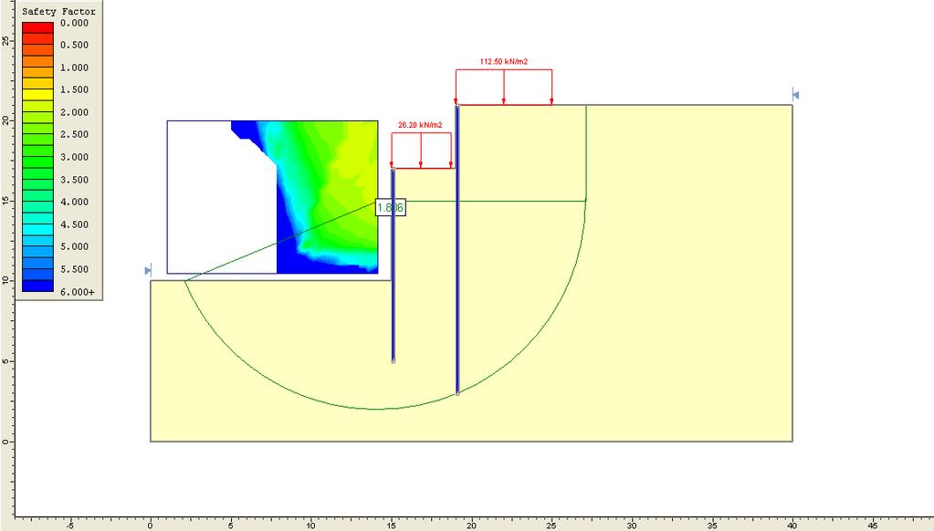
37 Micropiles(steel pipes of 125mm dia with 6mm thickness are considered as micro piles. Shear resistance = 0.4 f y A s = 0.4x250x0.785( )/1000 =224.2 kn. Horizontal component of shear resistance provides resistance for induced shear forces due to excavating and loading. Hence it is suggested to provide two rows of 125 mm outer dia., 6.5 mm thick in staggered direction at 250 mm centre to centre for a length of 3.5m from the centre line of railway track on both sides. This configuration results in higher factors of safety as shown in the Fig.3 (1.836 based on Bishop s method)
38

39 Use of micro piles as retention system
40

41
42 Concluding remarks Use of Micro piles is versatile in situ ground improvement technique and has been used very effectively in many stability problems. In many cases, micro piles are loaded tested following typical codes of practice (FHWA, pile load tests of Indian Standards etc). to measure the vertical and lateral capacities of the piles which are required in the validation of the design configuration and redesign if required.
43 References MICROPILE DESIGN AND CONSTRUCTION GUIDELINES (2000) US Department of Transportation, Federal Highway Administration, Priority Technologies Program
Ground Improvement Prof. G. L. Sivakumar Babu Department of Civil Engineering Indian Institute of Science, Bangalore
 Ground Improvement Prof. G. L. Sivakumar Babu Department of Civil Engineering Indian Institute of Science, Bangalore Module No. # 07 Lecture No. # 22 Micropiles (Refer Slide Time: 00:30) So, we would be
NPTEL Course. GROUND IMPROVEMENT Factors affecting the behaviour and performance of reinforced soil
 Lecture 27 NPTEL Course GROUND IMPROVEMENT Factors affecting the behaviour and performance of reinforced soil Prof. G L Sivakumar Babu Department of Civil Engineering Indian Institute of Science Bangalore
BEARING CAPACITY IMPROVEMENT USING MICROPILES A CASE STUDY
 BEARING CAPACITY IMPROVEMENT USING MICROPILES A CASE STUDY G.L. Sivakumar Babu 1, B. R.Srinivasa Murthy 2, D.S. N. Murthy 3, M.S. Nataraj 4 ABSTRACT Micropiles have been used effectively in many applications
Learning Outcomes. Background Definitions. Lesson 2 & 3. Definitions, Background, Classification, Applications and Costs
 Lesson 2 & 3 Definitions, Background, Classification, Applications and Costs schnabel-eng.com Learning Outcomes Define a micropile Describe the characteristics, advantages and limitations of micropiles
Downloaded from Downloaded from /1
 PURWANCHAL UNIVERSITY VI SEMESTER FINAL EXAMINATION-2003 LEVEL : B. E. (Civil) SUBJECT: BEG359CI, Foundation Engineering. Full Marks: 80 TIME: 03:00 hrs Pass marks: 32 Candidates are required to give their
The design of soil nailed structures to AS4678
 The design of soil nailed structures to AS4678 Chris Bridges Technical Principal - Geotechnics chris.bridges@smec.com 7 December 2016 1 Presentation Layout Introduction Soil Nailing in AS4678 Design Process
EFFICIENCY OF MICROPILE FOR SEISMIC RETROFIT OF FOUNDATION SYSTEM
 EFFICIENCY OF MICROPILE FOR SEISMIC RETROFIT OF FOUNDATION SYSTEM YAMANE TAKASHI, NAKATA YOSHINORI And OTANI YOSHINORI SUMMARY Micropile is drilled and grouted pile with steel pipes which diameters is
DESIGN-BUILD-TEST PROCESS FOR HIGH CAPACITY MICROPILES: CONSTRUCTION CASE STUDY ON DUTCHESS RAIL TRAIL BRIDGE FOUNDATIONS, POUGHKEEPSIE, NEW YORK
 ABSTRACT DESIGN-BUILD-TEST PROCESS FOR HIGH CAPACITY MICROPILES: CONSTRUCTION CASE STUDY ON DUTCHESS RAIL TRAIL BRIDGE FOUNDATIONS, POUGHKEEPSIE, NEW YORK James Barron 1, P.E., Thomas Hattala 2, P.E.,
Case Studies on Soil Nailed Retaining Systems for Deep Excavations
 Indian Geotechnical Conference 2010, GEOtrendz December 16 18, 2010 IGS Mumbai Chapter & IIT Bombay Case Studies on Soil Nailed Retaining Systems for Deep Excavations Murthy, B.R. Srinivasa Professor e-mail:
Jet Grouting to Increase Lateral Resistance of Pile Group in Soft Clay
 GROUND MODIFICATION, PROBLEM SOILS, AND GEO-SUPPORT 265 Jet Grouting to Increase Lateral Resistance of Pile Group in Soft Clay Kyle M. Rollins 1, Matthew E. Adsero 2, and Dan A. Brown 3 1 Prof. Civil &
INNOVATIVE SLOPE STABILISATION BY USING ISCHEBECK TITAN SOIL NAILS
 Dipl.-Wirt.Ing. Oliver Freudenreich Friedr. Ischebeck GmbH phone: ++49 2333 8305-0 Loher Str. 31 79 fax: ++49 2333 8305-55 e-mail: freudenreich@ischebeck.de D-58256 Ennepetal www.ischebeck.com INNOVATIVE
Pile foundations Introduction
 Engineering manual No. 12 Updated: 06/2018 Pile foundations Introduction Program: Pile, Pile CPT, Pile Group The objective of this engineering manual is to explain the practical use of programs for the
Favorable of grouted micropiles for the load transfer in weak sandy soils
 Favorable of grouted micropiles for the load transfer in weak sandy soils Ahmed Al-Obaidi 1,*, and Ansam Al-Karawi 2 1 Tikrit University, Tikrit, Iraq 2 Cihan University, Erbeil, Iraq Abstract. Micropiles
Typical set up for Plate Load test assembly
 Major disadvantages of field tests are Laborious Time consuming Heavy equipment to be carried to field Short duration behavior Plate Load Test Sand Bags Platform for loading Dial Gauge Testing Plate Foundation
BORED MICROPILES. I.S.M 2009 London (10 th to 13 th may) 9 th International worksop on micropiles - by A. Jaubertou -
 9 th International worksop on micropiles - by A. Jaubertou -") BORED MICROPILES FRENCH PRACTICE MICROPILES Definition Construction principles (type of micropile) Grouting effect Capacity ( structural and geotechnical ) Load test Connection considerations Mauritius
BORED MICROPILES FRENCH PRACTICE MICROPILES Definition Construction principles (type of micropile) Grouting effect Capacity ( structural and geotechnical ) Load test Connection considerations Mauritius
Investigation of Hollow Bar Micropiles in Cohesive Soil
 Western University Scholarship@Western Electronic Thesis and Dissertation Repository December 2013 Investigation of Hollow Bar Micropiles in Cohesive Soil Osama F. El Hadi Drbe The University of Western
Ground Improvement Using Steel Reinforcing Strips
 SAICE Geotechnical Division: Seminar on Ground Improvement Johannesburg, South Africa 8 & 9 October, 2001 Ground Improvement Using Steel Reinforcing Strips ACS Smith Reinforced Earth (Pty) Ltd, Johannesburg,
Micropile Lateral Load Testing in the Charleston, SC Area
 Micropile Lateral Load Testing in the Charleston, SC Area A special thanks to: William B. Wright, PE, Bryan T. Shiver, PE, Kenneth J. Zur, PE, Jackson C. Gosnell, PE, Theodore G. Padgett, PE, and William
Field Static Load Testing of Concrete Free Reticulated Micropiles System
 Field Static Load Testing of Concrete Free Reticulated Micropiles System A. Mehdizadeh 1, M. Disfani 2, R. Evans 3, E. Gad 4, A. Escobar 5 and W. Jennings 6 1 Research Assistant in Geotechnical Engineering,
Geoguide 6 The New Guide to Reinforced Fill Structure and Slope Design in Hong Kong
 Geoguide 6 The New Guide to Reinforced Fill Structure and Slope Design in Hong Kong Geotechnical Engineering Office Civil Engineering Department The Government of the Hong Kong Special Administrative Region
Compaction and Jet Grouting
 Compaction and Jet Grouting Alan Ringen, PE Senior Vice President Breakthroughs in Tunneling Short Course August 16, 2017 Grouting Principles Geotechnical Grouting: The injection of pumpable fluid materials
Class I and Class II Micro-Piles with Hollow- Bar Reinforcement. Load Tests and Performance Measurements
 Class I and Class II Micro-Piles with Hollow- Bar Reinforcement Load Tests and Performance Measurements Introduction Hollow-Bar Characteristics (based solely upon our observations and the comments of other
Direct Drilled New Micropile TITAN 127/111 for Underpinning Roman Bullring in Barcelona, Spain
 Folie 1 ISM 2007, 8 th International Workshop on Micropiles September 26-30, 2007, Toronto, Canada Direct Drilled New Micropile TITAN 127/111 for Underpinning Roman Bullring in Barcelona, Spain Dipl.-Ing.
twenty six concrete construction: foundation design ELEMENTS OF ARCHITECTURAL STRUCTURES: FORM, BEHAVIOR, AND DESIGN DR. ANNE NICHOLS SPRING 2013
 ELEMENTS OF ARCHITECTURAL STRUCTURES: FORM, BEHAVIOR, AND DESIGN DR. ANNE NICHOLS SPRING 2013 lecture twenty six concrete construction: www.tamu.edu foundation design Foundations 1 Foundation the engineered
Ching Guan Kee ABSTRACT
 Japanese Geotechnical Society Special Publication The 15th Asian Regional Conference on Soil Mechanics and Geotechnical Engineering Effects of base grouting and deep cement mixing on deep foundation bored
Table 1. Typical Soil Parameters Description Bulk Density, kn/m 3 Liquid Limit, % Plastic limit, % Natural Moisture Content, % Cohesion, kn/m 2 Compre
 CASE STUDY CONSTRUCTION OF HIGH ROAD EMBANKMENT OVER THICK SOFT SILTY CLAY- A CASE STUDY Radhakrishnan R, Geo-Enviro Engineers P Ltd, Chennai, Tamil Nadu, India, 044-24483522, geoenviro2012@gmail.com.
Testing of ground anchorages for a deep excavation retaining system in Bucharest
 XV Danube - European Conference on Geotechnical Engineering (DECGE 2014) H. Brandl & D. Adam (eds.) 9-11 September 2014, Vienna, Austria Paper No. 176 Testing of ground anchorages for a deep excavation
BEARING CAPACITY DURING EARTHQUAKE OF THE SPREAD FOOTING REINFORCED WITH MICROPILES
 BEARING CAPACITY DURING EARTHQUAKE OF THE SPREAD FOOTING REINFORCED WITH MICROPILES K MIURA 1, Y TSUKADA 2, Y TSUBOKAWA 3, M ISHITO 4, N NISHIMURA 5, Y OHTANI 6 And G L YOU 7 SUMMARY The development of
twenty four foundations and retaining walls Foundation Structural vs. Foundation Design Structural vs. Foundation Design
 ALIED ARCHITECTURAL STRUCTURES: STRUCTURAL ANALYSIS AND SYSTEMS DR. ANNE NICHOLS SRING 2018 lecture twenty four Foundation the engineered interface between the earth and the structure it supports that
twenty seven concrete construction: foundation design Foundation Structural vs. Foundation Design Structural vs. Foundation Design
 ARCHITECTURAL STRUCTURES: FORM, BEHAVIOR, AND DESIGN DR. ANNE NICHOLS SRING 2017 lecture twenty seven Foundation the engineered interface between the earth and the structure it supports that transmits
Design of Soil Nailed Walls According to AS
 Design of Soil Nailed Walls According to AS4678-2002 Chris Bridges, SMEC, Brisbane, Queensland Keywords: soil nail, retaining wall, Australian Standards ABSTRACT The use of soil nails in the construction
GEOTECHNICAL RESISTANCE FACTORS
 Chapter 9 GEOTECHNICAL RESISTANCE FACTORS Final SCDOT GEOTECHNICAL DESIGN MANUAL 9-i Table of Contents Section Page 9.1 Introduction... 9-1 9.2 Soil Properties... 9-2 9.3 Resistance Factors for LRFD Geotechnical
EXPERIMENTAL STUDY ON LOAD SETTLEMENT BEHAVIORS OF MICRO PILE UNDER VERTICAL LOADING
 EXPERIMENTAL STUDY ON LOAD SETTLEMENT BEHAVIORS OF MICRO PILE UNDER VERTICAL LOADING Prof.HARISH C 1, MANJUNATHA.M 2 1 Assistant, professor, Department of Civil Engineering, EWIT, Bengaluru, Karnataka,
Lateral Loads on Micropiles. Thomas Richards Nicholson Construction Company
 Lateral Loads on Micropiles Thomas Richards Nicholson Construction Company Micropile Names Micropile ( DFI & FHWA) = Pin Pile SM ( Nicholson) = Minipile (previously used by Hayward Baker and used in UK)
Static and Dynamic Analyses of Micropiles to Reinforce the High Railway Embankments on Loose Beds
 Journal of Rehabilitation in Civil Engineering 1-2 (2013) 80-89 journal homepage: http://civiljournal.semnan.ac.ir/ Static and Dynamic Analyses of Micropiles to Reinforce the High Railway Embankments on
MICROPILE LATERAL LOAD TESTING IN CHARLESTON, SOUTH CAROLINA, USA
 MICROPILE LATERAL LOAD TESTING IN CHARLESTON, SOUTH CAROLINA, USA William B. Wright, et. al. 1 ABSTRACT With increasing frequency, micropiles are being used as a foundation solution within the Charleston,
SAS Micropile Manual. Basic dimensioning and design recommendations. Table of Content:
 SAS Micropile Manual Basic dimensioning and design recommendations Table of Content: Page System Description 2 Load Capacities 2 Minimum Drill Hole Diameter 3 Load Transfer to Ground 4 Corrosion Protection
GEO-SLOPE International Ltd, Calgary, Alberta, Canada Tie-back Wall
 1 Introduction Tie-back Wall This example simulates the sequential construction of a sheet-pile shoring wall tied back with pre-stressed anchors. The purpose is to demonstrate the steps involved in modeling
Grouting Bilfinger Spezialtiefbau GmbH
 Grouting Bilfinger Spezialtiefbau GmbH Goldsteinstrasse 114 D-60528 Frankfurt Phone: +49 69 6688-345 Fax: +49 69 6688-277 Email: info.spezialtiefbau@bilfinger.com www.foundation-engineering.bilfinger.com
Evaluation of negative skin friction on sheet pile walls at the Rio Grande dry dock, Brazil
 Geotechnical Aspects of Underground Construction in Soft Ground Viggiani (ed) 2012 Taylor & Francis Group, London, ISBN 978-0-415-68367-8 Evaluation of negative skin friction on sheet pile walls at the
Comparison of the results of load test done on stone columns and rammed aggregate piers using numerical modeling
 Comparison of the results of load test done on stone columns and rammed aggregate piers using numerical modeling Ece Kurt Civil Eng., M.Sc.& Geoph. Eng., Istanbul, Turkey Berrak Teymur Asst. Prof. Dr.,
1.364 ADVANCED GEOTECHNICAL ENGINEERING HOMEWORK No. 5
 .364 ADVANCED GEOTECHNICAL ENGINEERING HOMEWORK No. Due: Friday December 2. This question concerns the stability of an open slope cutting that will be used to provide construction access for a 3.2m deep
Performance of Reinforced Earth Retaining Wall with Fly Ash under Static and Dynamic Loading
 Performance of Reinforced Earth Retaining Wall with Fly Ash under Static and Dynamic Loading 1 Umesh Kumar N, 2 Padmashree M. Kalliamni 1 Geotechnical Engineer, 2 Assistant professor, 1 Civil Engineering
STATIC ALTERNATING CYCLIC HORIZONTAL LOAD TESTS ON DRIVEN
 STATIC ALTERNATING CYCLIC HORIZONTAL LOAD TESTS ON DRIVEN STEEL PIPE PILES OF FOUNDATIONS FOR HIGHWAY BRIDGES Kouichi TOMISAWA, Civil Engineering Research Institute of Hokkaido, Japan Satoshi NISHIMOTO,
USE OF DIPP PILES FOR A NEW SUP BRIDGE IN WEST MELBOURNE
 USE OF DIPP PILES FOR A NEW SUP BRIDGE IN WEST MELBOURNE If you want to put a photo on the title slide use this layout with colour photos (delete this box) Michael Wei, Jawad Zeerak & David Barton 8 th
GEOSYNTHETICS ENGINEERING: IN THEORY AND PRACTICE
 GEOSYNTHETICS ENGINEERING: IN THEORY AND PRACTICE Prof. J. N. Mandal Department of civil engineering, IIT Bombay, Powai, Mumbai 400076, India. Tel.022-25767328 email: cejnm@civil.iitb.ac.in Module-5 LECTURE-
DYNAMIC-RESPONSE CHARACTARISTICS OF STRUCTURES WITH MICROPILE FOUNDATION SYSTEM
 937 DYNAMIC-RESPONSE CHARACTARISTICS OF STRUCTURES WITH MICROPILE FOUNDATION SYSTEM TAKAHIRO KISHISHITA 1, ETURO SAITO 2 And FUSANORI MIURA 3 SUMMARY Piled raft foundation and PHC nodular piles, which
Code No: RR Set No. 1
 Code No: RR320101 Set No. 1 III B.Tech Supplimentary Examinations, Aug/Sep 2008 GEOTECHNICAL ENGINEERING (Civil Engineering) Time: 3 hours Max Marks: 80 Answer any FIVE Questions All Questions carry equal
Analyzing and Investigating the Effect of Nailing on Stabilization Soil Trenches of Sand with Medium Density via Analytical Limit Equilibrium
 Modern Applied Science; Vol. 0,. ; 0 ISSN 93844 EISSN 9385 Published by Canadian Center of Science and Education Analyzing and Investigating the Effect of Nailing on Stabilization Soil Trenches of Sand
Chapter 16 DEEP FOUNDATIONS
 Chapter 16 DEEP FOUNDATIONS Final SCDOT GEOTECHNICAL DESIGN MANUAL June 2010 SCDOT Geotechnical Design Manual Deep Foundations Table of Contents Section Page 16.1 Introduction...16-1 16.2 Design Considerations...16-3
Three-dimensional computer simulation of soil nailing support in deep foundation pit
 Three-dimensional computer simulation of soil nailing support in deep foundation pit Abstract Chang Zhi Zhu 1,2*, Quan Chen Gao 1 1 School of Mechanics & Civil Engineering, China University of Mining &
SEISMIC RETROFIT OF AN UNDERGROUND RESERVOIR. Robert Small 1, Rob Jameson 2
 ABSTRACT SEISMIC RETROFIT OF AN UNDERGROUND RESERVOIR Robert Small 1, Rob Jameson 2 Seismic Upgrade of the University Mound Reservoir North Basin included 542 micropiles with 1335 KN (300 kip) design capacity
5-20 FOUNDATION REPORT/GEOTECHNICAL DESIGN
 5-20 FOUNDATION REPORT/GEOTECHNICAL DESIGN REPORT CHECKLIST FOR EARTH RETAINING SYSTEMS Introduction This checklist was developed to assist the geotechnical project professionals in preparing the Foundation
Case study on a deep excavation in Baku: Flame Towers project earth retaining system
 Case study on a deep excavation in Baku: Flame Towers project earth retaining system H. A. Afatoglu 1 ENAR Engineers Architects & Consultants, Istanbul, Turkey ABSTRACT Baku Flame Towers Project, consisting
Analysis of Four Load Tests on Augered Cast-in-Place Piles in the Texas Gulf Coast Soils Raghu Dass, PE, Woodward Vogt, PE, and Frank Ong, PE
 Analysis of Four Load Tests on Augered Cast-in-Place Piles in the Texas Gulf Coast Soils Raghu Dass, PE, Woodward Vogt, PE, and Frank Ong, PE Presented By: Raghu N. Dass, Ph. D., P.E. TSI Laboratories,
Northport Berth 3 design and construction monitoring
 Proc. 18 th NZGS Geotechnical Symposium on Soil-Structure Interaction. Ed. CY Chin, Auckland Lucy Coe, Nicola Ridgley, Do Van Toan Beca Infrastructure Limited, Auckland, NZ Keywords: retaining wall, deflections,
geopier Lateral resistance
 technical bulletin No. 4 geopier Lateral resistance This Technical Bulletin discusses the behavior of Geopier supported shallow foundation systems when subjected to lateral loads. Lateral loads are applied
Performance Objectives and the AASHTO Guide Specifications for LRFD Seismic Bridge Design
 Performance Objectives and the AASHTO Guide Specifications for LRFD Seismic Bridge Design Elmer E. Marx, PE, SE State of Alaska DOT&PF Bridge Section Juneau, Alaska Performance Objectives AASHTO Guide
TUNNEL LINER PLATE INTRODUCTION GENERAL APPLICATIONS CHAPTER 11
 CHAPTER 11 INTRODUCTION The open-trench method of placing underground conduits is commonly used on new construction of culverts, sewers and underpasses. Interference with traffic, as well as inconvenience
Improving the Bearing capacity of foundations using micropiles
 Improving the Bearing capacity of foundations using micropiles Pourya Haghighy PhD Scholar Department of Civil and Environmental Engineering, College of Engineering The University of Adelaide Australia
Rewa Engineering College, Rewa. Rewa
 Rewa Engineering College, Rewa Rewa 486001 Department OF Civil Engineering VIII TH SEMESTER GEOTECHNICAL ENGG II SESSION: 2017-18 Prepared by: Anoop Kumar Tiwari Approved by (HOD) 1 OBJECTIVES Design of
RIGID INCLUSIONS. Rigid Inclusions offer an economical approach for building on sites underlain by soft soil.
 H A Y W A R D B A K E R I N C. RIGID INCLUSIONS Rigid Inclusions offer an economical approach for building on sites underlain by soft soil. Above: HBI installed Rigid Inclusions on a congested downtown
Challenges of Offshore Geotechnical Engineering
 Challenges of Offshore Geotechnical Engineering OCE 582 - Seabed Geotechnics Professor Kate Moran presented by Ursula Hebinck Overview Content of Paper recent developments in offshore site investigation
VERTICAL BARRIERS SLURRY TRENCH BARRIERS: excavation equipment. prof. E. Fratalocchi Environmental Geotechnics Waste and polluted sites containment
 VERTICAL BARRIERS SLURRY TRENCH BARRIERS: excavation equipment VERTICAL BARRIERS SLURRY TRENCH BARRIERS: excavation equipment rotary drill hydro-mill backhoe Clamshell + Kelly bar VERTICAL BARRIERS SLURRY
CONCEPT OF UNDER REAMED CEMENTED STONE COLUMNS FOR SOFT CLAY GROUND IMPROVEMENT
 IGC 2009, Guntur, INDIA CONCEPT OF UNDER REAMED CEMENTED STONE COLUMNS FOR SOFT CLAY GROUND IMPROVEMENT Y.S. Golait Professor Emeritus, Dept. of Civil Engg., RKN Engineering College, Nagpur 440013, India.
WHAT IS A FOUNDATION?
 WHAT IS A FOUNDATION? from Underground by David Macaulay (1976) The element of a structure that transfers loads to the underlying ground with performance consistent with the design of the structure. Loads
EXPERIMENTAL PROGRAMME
 CHAPTER 3 EXPERIMENTAL PROGRAMME 3.1 INTRODUCTION The critical review of the literature presented in the previous chapter reveals the limitations of the experimental studies carried out so far in the field
Sabah Shawkat Cabinet of Structural Engineering 2017
 3.9 Concrete Foundations A foundation is a integral part of the structure which transfer the load of the superstructure to the soil without excessive settlement. A foundation is that member which provides
FURTHER TECHNICAL INFORMATION IN RELATION TO THE OPERATIONS OF OUR GROUP
 A. TECHNICAL INFORMATION OF OUR FOUNDATION WORKS The major types of our foundation works (with illustrative diagram, where applicable) are set out below: 1. Bored piles 0.80m 3.5m pile shaft By Grabbing
PILE DESIGN METHOD FOR IMPROVED GROUND USING THE VACUUM CONSOLIDATION METHOD
 PILE DESIGN METHOD FOR IMPROVED GROUND USING THE VACUUM CONSOLIDATION METHOD K Tomisawa, Civil Engineering Research of Hokkaido, Japan S Nishimoto, Civil Engineering Research of Hokkaido, Japan Abstract
Analysis of skin friction in prebored and precast piles
 Japanese Geotechnical Society Special Publication The 6th Japan-Korea Geotechnical Workshop Analysis of skin friction in prebored and precast piles Sangseom Jeong i), Gyoungja Jung ii), Dohyun Kim iii)
Long-Term Settlement Performance Monitoring, I-15 Reconstruction Project, Salt Lake City, UT. Steven Bartlett, University of Utah
 1 Long-Term Settlement Performance Monitoring, I-15 Reconstruction Project, Salt Lake City, UT Steven Bartlett, University of Utah Roadway Widening (I-15 Project) Salt Lake City Utah, USA 2002 Host of
Partial Factors of Safety
 APPENDIX A Partial Factors of Safety A.I Introduction The capacity of single piles in axial compression should provide an adequate safety factor against failure due to insufficient soil-pile interface
NPTEL Course GROUND IMPROVEMENT
 Lecture 8 NPTEL Course GROUND IMPROVEMENT Prof. G L Sivakumar Babu Department of Civil Engineering Indian Institute of Science Bangalore 560012 Email: gls@civil.iisc.ernet.in Vibro-compaction methods Compaction
 techie-touch.blogspot.com www.vidyarthiplus.com CE2305 FOUNDATION ENGINEERING 2 MARKS QUESTIONS & ANSWERS 16 MARKS QUESTIONS UNIT -1 1. What are components of total foundation settlement? elastic settlement,
Strength Behaviour of Cohesive Soils Reinforced with Fibers
 International Journal of Civil Engineering Research. ISSN 2278-3652 Volume 5, Number 4 (2014), pp. 353-360 Research India Publications http://www.ripublication.com/ijcer.htm Strength Behaviour of Cohesive
A Case Study: Foundation Design in Liquefiable Site
 RESEARCH ARTICLE OPEN ACCESS A Case Study: Foundation Design in Liquefiable Site Tahar Ayadat* *(Department of Civil Engineering, College of Engineering, PMU University, P.O. Box 1664, Al-Khobar, 31952,
CHAPTER 8 BEARING CAPACITY ANALYSES FOR EARTHQUAKES
 CHAPTER 8 BEARING CAPACITY ANALYSES FOR EARTHQUAKES The following notation is used in this chapter: SYMBOL DEFINITION B Width of footing B Reduced footing width to account for eccentricity of load c Cohesion
Council on Tall Buildings
 Structure Design of Sino Steel (Tianjin) International Plaza Xueyi Fu, Group Chief Engineer, China Construction Design International 1 1 Brief of Project 2 Location: Tianjin Xiangluowan Business District
Upgrading the shear strength of non-ductile reinforced concrete frame connections using FRP overlay systems
 Upgrading the shear strength of non-ductile reinforced concrete frame connections using FRP overlay systems Mohamad J. Terro Associate Professor. Civil Engineering Department, Kuwait University. Sameer
Pavement materials: Soil
 Pavement materials: Soil Lecture Notes in Transportation Systems Engineering Prof. Tom V. Mathew Contents 1 Overview 1 2 Sub grade soil 2 2.1 Desirable properties................................ 2 2.2
Lizzi Lecture Performance of Seismic Retrofits with High Capacity Micropiles. Jiro Fukui. Public Works Research Institute, Japan
 Lizzi Lecture 2006 Performance of Seismic Retrofits with High Capacity Micropiles Jiro Fukui Public Works Research Institute, Japan 1 Topics 1. Introduction (Background of Research) 2. Joint Research A)
Evaluation of Pseudo Static coefficient for Soil nailed walls on the basis of Seismic behavior levels
 Research Journal of Recent Sciences ISSN 2277-2502. Evaluation of Pseudo Static coefficient for Soil nailed walls on the basis of Seismic behavior levels Abstract Majid yazdandoust 1*, Ali komak panah
Upon speaking with the representatives with Technical Foundations as well as Walder Foundations, it was determined that:
 As part of our analyses, we have considered the design and construction of the cantilever retaining wall that will be located along the north side of Lucks Lane, between Falling Creek and Gladstone Glen
TABLE OF CONTENTS. 0 Structural calculations 0.1 General 0.2 Safety concept 0.3 Calculations for waterfront structures
 Arbeitsausschuß "Ufereinfassungen" der Hafentechnischen Gesellschaft e.v. Recommendations of the Committee for Waterfront Structures Harbours and Waterways 9., completely revised Edition TABLE OF CONTENTS
Better ZSOIL, Better Geotechnical Analysis
 SYMPOSIUM : NUMERICS IN GEOTECHNICS & STRUCTURES 25 YEARS ZSOIL.PC DATE :30-31.08.2010 Better ZSOIL, Better Geotechnical Analysis 3D Numerical Analysis of A Building Under Construction Collapse in Shanghai
DESIGN AND DETAILING OF RETAINING WALLS
 DESIGN AND DETAILING OF RETAINING WALLS (For class held from nd April 07) Dr. M. C. Nataraja, Professor, Civil Engineering Department, Sri Jayachamarajendra Collge of Engineering, Mysore-5a70 006 Phone:
Construction Technology B (CON4313)
") 3 - Basement 1 Quick Revision 1.1 Problems arising from basement construction a. Excavation method. b. Surface and ground water control c. Lateral stability of basement excavation. d. Stability of adjoining
3 - Basement 1 Quick Revision 1.1 Problems arising from basement construction a. Excavation method. b. Surface and ground water control c. Lateral stability of basement excavation. d. Stability of adjoining
Settlement Reduction Effect of Advanced Back-to-Back Reinforced Retaining Wall
 IJR International Journal of Railway Vol. 6, No. 3 / September 2013, pp. 107-111 The Korean Society for Railway Settlement Reduction Effect of Advanced Back-to-Back Reinforced Retaining Wall Koh, Taehoon,
A MODEL STUDY ON LATERAL BEHAVIOUR OF MICROPILE UNDER INCLINED COMPRESSIVE LOADS IN SAND
 A MODEL STUDY ON LATERAL BEHAVIOUR OF MICROPILE UNDER INCLINED COMPRESSIVE LOADS IN SAND Shyma Jose 1, Vishnu M Prakash 2, Hanna Paul 3 1P.G. Student, Department of Civil Engineering, Saintgits College
Subsoil Bearing Capacity from Load Test Results In Two Locations in Rivers State, Nigeria
 IOSR Journal of Applied Geology and Geophysics (IOSR-JAGG) e-issn: 2321 0990, p-issn: 2321 0982.Volume 4, Issue 4 Ver. II (Jul. - Aug. 2016), PP 27-35 www.iosrjournals.org Subsoil Bearing Capacity from
Modules for Graduate Certificate in Geotechnical Engineering
 Modules for Graduate Certificate in Geotechnical Engineering * SkillsFuture credit (available for Singapore Citizens, subject to approval) ^ SkillsFuture Singapore (SSG) subsidy available for eligible
Challenges in Design and Construction of Deep Excavation With Case Studies - KVMRT in KL Limestone
 Challenges in Design and Construction of Deep Excavation With Case Studies - KVMRT in KL Limestone Gue See Sew G&P Professionals Sdn Bhd www.gnpgroup.com.my 20 July 2016 CONTENTS INTRODUCTION SOIL PARAMETERS
DHANALAKSHMI COLLEGE OF ENGINEERING, CHENNAI DEPARTMENT OF CIVIL ENGINEERING 2 MARK QUESTIONS WITH ANSWERS CE FOUNDATION ENGINEERING UNIT 1
 DHANALAKSHMI COLLEGE OF ENGINEERING, CHENNAI DEPARTMENT OF CIVIL ENGINEERING 2 MARK QUESTIONS WITH ANSWERS CE6502 - FOUNDATION ENGINEERING Subject Code: CE6502 UNIT 1 1. What are the informations obtained
Over the last decade, drilled and postgrouted micropile foundations have
 Seismic Design of Micropile Foundation Systems Leo Panian, S.E., and Mike Korolyk, S.E. Over the last decade, drilled and postgrouted micropile foundations have come to be increasingly relied on for resisting
Sheeting Wall Analysis by the Method of Dependent Pressures
 Sheeting Wall Analysis by the Method of Dependent Pressures Veronika Vaneckova FINE Ltd., Prague, Czech Republic. E-mail: veronika.vaneckova@fine.cz. Jiri Laurin FINE Ltd., Prague, Czech Republic. E-mail:
A Review of Soil Nailing Design Approaches
 A Review of Soil Nailing Design Approaches S.N.L. Taib 1 Abstract A number of design manuals and recommendations; namely by the HA 68 [4] (U.K.), BS8006 [1] (U.K.), RDGC [7] (France) and FHWA [5] (USA)
Design and Construction of Drilled Full Displacement Piles using the Penetration Resistance Method
 SUPERPILE 2009 Burlingame, CA Design and Construction of Drilled Full Displacement Piles using the Penetration Resistance Method Peter Faust Malcolm Drilling Company Inc. Alexandria Parking Garage, San
ANCHORING WITH BONDED FASTENERS
 ANCHORING WITH BONDED FASTENERS Ronald A. Cook and Robert C. Konz Department of Civil Engineering, University of Florida, USA Abstract Bonded fasteners have been used extensively during the past twenty